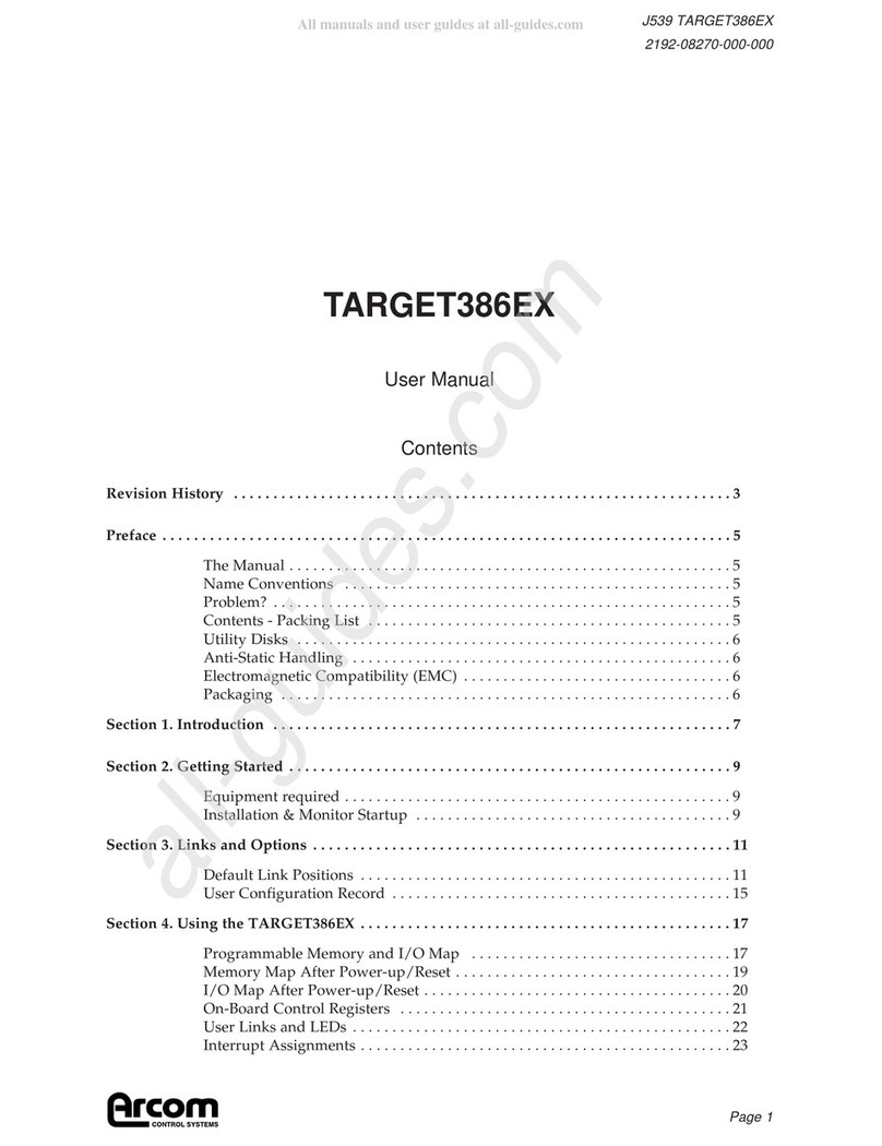
Arcom Director DS2 User manual

DS2/DS4 Hardware Manual
Page 1
DS2/DS4
DIRECTOR
Hardware Manual
Product Information
Full information about other Arcom products is available on our WebSite at: www.arcom.com
Useful Contact Information
Customer support US Customer Support Europe
Tel: 1 913 549 1000
Fax: 1 913 549 1001
E-mail [email protected]
Tel: 44 (0)1223 412 428
Fax: 44 (0)1223 403 409
E-mail: [email protected]
Sales offices:
United States:
Arcom Control Systems Inc
7500 West 161st Street
Overland Park, KS 66085 USA
Tel: 913 549 1000
Fax: 913 549 1002
E-mail:
United Kin dom:
Arcom Control Systems Ltd
Clifton Road
Cambridge CB1 7EA, UK
Tel: 01223 411 200
Fax: 01223 410 457
E-mail:
Sales Hotlines:
Bel ium:
Groen Nummer:
Tel: 0800 7 3192
Fax: 0800 7 3191
France:
Numero Vert
Tel: 0800 90 84 06
Fax: 0800 90 84 12
Germany:
Kostenlose Infoline:
Tel: 08001 824 511
Fax: 08001 824 512
Netherlands:
Gratis 0800 Nummer:
Tel: 0800 0221136
Fax: 0800 0221148
Italy:
Numero Verde:
Tel: 0800 790841
Fax: 0800 780841
Whilst Arcom’s sales team is always available to assist you in making your decision, the final choice of boards
or systems is solely and wholly the responsibility of the buyer. Arcom’s entire liability in respect of the boards
or systems is as set out in Arcom’s standard terms and conditions of sale.
If you intend to write your own low-level software, you can start with the source code on the disk that is
supplied. This is example code only to illustrate use on Arcom’s products. It has not been commercially
tested. No warranty is made in respect of this code and Arcom shall incur no liability whatsoever or
howsoever arising from any use made of the code.
© 2005 Arcom Control Systems Inc
All trademarks recognized.
Arcom Control Systems Ltd
operate a company-wide uality
management system which has
been certified by the British
Standards Institution (BSI) as
compliant with ISO9001:1994

DS2/DS4 Hardware Manual
Page 2
Contents
1 Revision History...........................................................................................................................4
2 Preface ..........................................................................................................................................5
2.1 Scope of this Manual......................................................................................................................5
2.2 Name Conventions.........................................................................................................................5
2.3 Anti-Static Handling........................................................................................................................5
2.4 Electromagnetic Compatibility (EMC) ............................................................................................5
2.5 Packaging ......................................................................................................................................5
2.6 Disclaimer ......................................................................................................................................5
3 Introduction ..................................................................................................................................6
4 DS2/DS4 Unit Hardware...............................................................................................................7
4.1 Specifications .................................................................................................................................8
4.1.1 Battery Safety Guidelines...............................................................................................................8
4.2 Enclosure .......................................................................................................................................9
4.2.1 DS2/DS4 Internal Arrangement ...................................................................................................11
4.2.2 I/O Expandability Options.............................................................................................................11
4.3 Processor Board – AIM104-386EX ..............................................................................................12
4.3.1 AIM104-386EX Link Settings .......................................................................................................12
4.3.2 SCT-AIM104 Link Settings...........................................................................................................13
4.3.3 RS-232 Serial Interface: COM0 to COM3 ....................................................................................14
4.3.4 RS-485 Serial Interface: COM3 ...................................................................................................15
5 Optional I/O Boards ...................................................................................................................17
5.1 AIM104–Ether Ethernet Interface.................................................................................................17
5.1.1 AIM104 Ether Link Settings..........................................................................................................17
5.2 AIM104-SER4 Serial Interface .....................................................................................................18
5.2.1 AIM104-SER4 Specifications .......................................................................................................18
5.2.2 SER4 Link Settings – 1st card .....................................................................................................18
5.2.3 SER4 Link Settings – 2nd Card ...................................................................................................19
5.2.4 Signal Interface to 9 way ‘D’ type connectors ..............................................................................20
5.3 AIM104-COM4 Serial Interface ....................................................................................................21
5.3.1 AIM104-COM4 Specifications ......................................................................................................21
5.3.2 AIM104-COM4 Link Settings........................................................................................................21
5.3.3 Signal Interface to 9 way ‘D’ type connectors ..............................................................................25
5.4 AIM104 - MULTI-IO......................................................................................................................26
5.4.1 Board Specification ......................................................................................................................26
5.4.2 Analog Input Specifications..........................................................................................................26
5.4.3 Digital Input Specifications ...........................................................................................................26
5.4.4 Analog Output Specifications .......................................................................................................26
5.4.5 MULTI-IO Link Settings................................................................................................................27
5.4.6 AIM104-MULTI-IO Connection Wiring .........................................................................................28
5.5 AIM104 - RLY8/IN8 ......................................................................................................................29
5.5.1 Board Specification ......................................................................................................................29
5.5.2 Digital Input Specifications ...........................................................................................................29
5.5.3 Digital Output Specifications ........................................................................................................29
5.5.4 RLY8/IN8 Link Settings ................................................................................................................29
5.5.5 AIM104-RLY8/IN8 Connection Wiring..........................................................................................31
5.6 AIM104 – IN16 .............................................................................................................................32
5.6.1 Board Specification ......................................................................................................................32
5.6.2 AIM104-IN16 Link Settings ..........................................................................................................32

DS2/DS4 Hardware Manual
Page 3
5.6.3 AIM104-IN16 Connection Wiring..................................................................................................34
5.7 AIM104 – PULSE .........................................................................................................................35
5.7.1 Board Specification ......................................................................................................................35
5.7.2 AIM104-PULSE Link Settings ......................................................................................................35
5.7.3 AIM104-PULSE Connection Wiring .............................................................................................37
5.8 AIM104 – HBI...............................................................................................................................38
5.8.1 HART Input Specifications ...........................................................................................................38
5.8.2 Analog Output Specifications .......................................................................................................38
5.8.3 AIM104-HBI Link Settings ............................................................................................................39
5.8.4 I/O Connection using Ribbon Cabling ..........................................................................................40
5.8.5 HART Wiring Diagrams................................................................................................................41

DS2/DS4 Hardware Manual
Page 4
1 Revision History
Manual Comments
Revision 1.0 11-Aug-05 Initial release of DS2/DS4 Hardware Manual, separated
from older APEX/Director Hardware Manual

DS2/DS4 Hardware Manual
Page 5
2 Preface
2.1 Scope of this Manual
This manual details the hardware of the DS2/DS4 Director.
2.2 Name Conventions
All numbers are in decimal unless otherwise indicated. Where a number is prefixed by ‘0x’, the
value is in hexadecimal format.
2.3 Anti-Static Handlin
This board contains CMOS devices that could be damaged in the event of static electricity being
discharged through them. At all times, please observe anti-static precautions when handling the
board and always unpack and install it in an anti-static working area.
2.4 Electroma netic Compatibility (EMC)
The DS2/DS4 is classified as a component with regard to the European Community EMC
regulations and it is the user’s responsibility to ensure that systems using the board are compliant
with the appropriate EMC standards.
Arcom EMC tests of the DS2/DS4 have shown that the RF emissions of the board are well below
standard international EMC limits and that it is unlikely to contribute significantly to the RF emissions
spectrum of any system in which it is used.
2.5 Packa in
Please ensure that should a board need to be returned to Arcom, it is adequately packed. Use an
anti-static bag for the board and use a box, not bag, to physically protect the board.
2.6 Disclaimer
The information in this manual has been carefully checked and is believed to be accurate. Arcom
Control Systems assumes no responsibility for any infringements of patents or other rights of third
parties that may result from its use.
Arcom Control Systems assumes no responsibility for any inaccuracies that may be contained in
this document. Arcom Control Systems makes no commitment to update or keep current the
information contained in this manual.
Arcom Control Systems reserves the right to make improvements to this document and/or product at
any time and without notice.

DS2/DS4 Hardware Manual
Page 6
3 Introduction
This manual covers the hardware information for the Director product line. It details the standard and
optional hardware, specifications, and information required by the system designer for setting up the unit
configuration. The different models of Director use the same software operating system and are differentiated
from each other simply based on the physical enclosure and hardware platform.
The DS2/DS consists of a processor board and base board containing four serial channels. Optional I/O
cards may be added to the board stack via a 16-bit PC/10 header to provide Ethernet, additional
communication channels, analog and digital I/O, or HART protocol ports. All boards are mounted in an
industrial metal enclosure. Director units are provided fully tested and may have customer-specific
configurations when they leave the factory.
By default, the processor board has four serial ports, one of which may be configured for two-wire RS- 85.
These four ports are intended for local configuration and programming, and for connection to external field
devices.
The serial ports are configured using the ACE software tool. Using Windows HyperTerminal or another
terminal emulator, one communications port may be used to download the configuration file generated by
ACE and provide diagnostic capabilities. I/O signals from optional I/O boards are cabled from the PC/10
stack using a 50-way header and may be connected to an external breakout device to provide screw
terminations.

DS2/DS4 Hardware Manual
Page 7
4 DS2/DS4 Unit Hardware
The Director unit always has the same basic hardware, and this chapter describes the necessary links and pin-
outs that need to be understood before the system can be used. Director units are provided fully tested and are
typically supplied from the factory with a default software configuration.
The Director consists of the following hardware components:
• Enclosure - metal housing to contain processor and provide mounting arrangement
• Baseboard - contains power supply, built-in communication port terminations, and slots for installing
card
• Microprocessor - 386EX processor mounts to the Baseboard
• Optional I/O - PC/10 cards provide expansion I/O. Typically, the only card installed on a DS2 is the
Ethernet controller board (AIM10 -ETHER).
• Internal Connections - connects internal I/O to outside of enclosure
This section describes the power supply, baseboard, I/O connections, and the microprocessor.

DS2/DS4 Hardware Manual
Page 8
4.1 Specifications
Processor Intel 386EX 25 MHz
Memory 1 Mb SRAM
1 Mb Flash (for storage of operating system and configuration)
Battery Non-rechargeable 3V lithium
for maintaining Real Time Clock and SRAM
Temperature: - 0 to +70º C (operating)
-50 to +85º C (storage)
Humidity: 0 to 95% relative, non-condensing
Input Power: 18 to 36 VDC
Optional: 12V DC nominal (9 to 18 VDC)
or, 8V DC nominal (36 to 72 VDC)
Power Consumption: .5 Watts (with standard board set). In-rush current on startup is approximately 2A
momentarily. Additional power required for optional boards, listed in each section of
this manual.
Standard board set includes: AIM10 -386EX processor, AIM10 -Ether,
and SCT-AIM10 baseboard.
Weight 0.737 kg (1.625 lbs.), excluding optional cards
4.1.1 Battery Safety Guidelines
WARNING: Battery is non-rechar eable. Dan er of explosion if battery (lithium cell)
is rechar ed or incorrectly replaced. Replace only with the same or equivalent type
recommended by the manufacturer. Dispose of used batteries accordin to the
manufacturer’s instructions.
Replacement of the lithium cell is to be carried out by qualified (service) personnel only. The battery on the
Director is provided to maintain the on-board real-time clock when input power is removed.

DS2/DS4 Hardware Manual
Page 9
4.2 Enclosure
The Director unit consists of a processor board and other circuit boards installed in a panel mount metal
enclosure, which includes interior electrical shielding. Enclosure and mounting dimensions are shown below.
DS2 Mounting Dimensions
4.125 in. (105 mm)
Front View
Drg. S15039-01
- G
P
O
W
E
R
R
U
N
S
T
A
T
COM 1 COM 0
COM 3 COM 2
N
E
T
3.188 in. (82 mm)
6.57 in. (167 mm)
5.5 in. (140 mm)
max (adjustable)
4.84 in. (123 mm)

DS2/DS4 Hardware Manual
Page 10
DS Mounting Dimensions
4.125 in. (105 mm)
Front View
Drg. S15039-05
- G
P
O
W
E
R
R
U
N
S
T
A
T
COM 1 COM 0
COM 3 COM 2
N
E
T
4.41 in. (112 mm)
7.95 in. (202 mm)
6.89 in. (175 mm)
max (adjustable)
4.84 in. (123 mm)
By default, the processor board has four serial ports available on-board. These are brought to the front of the
enclosure via a termination board (SCT-AIM10 ). Ethernet is provided via an expansion board (AIM10 -
ETHER) cabled to an RJ- 5 connector on the front of the unit.

DS2/DS4 Hardware Manual
Page 11
4.2.1 DS2/DS4 Internal Arran ement
Several circuit boards make up a DS2/DS , which are connected together internally as shown in the following
diagram.
Optional Board #1Optional Board #1
Processor BoardProcessor Board
Front
face plate
Baseboard contains:
•24VDC Power Supply (18-36v)
•Jumpers for 1 RS-485
•Battery backup for RTC
Processor board:
•AIM104-386EX
•Runnin @ 25MHz
•Four base serial ports
Side View Cutaway
TOP
Baseboard
Com
Conn
0 - 3
Baseboard
Com
Conn
0 - 3
Only in
Director
Series IV
Only in
Director
Series IV
To RJ-45To RJ-45Connectors
on Backplate Optional Board #2Optional Board #2
Optional Board #3Optional Board #3
One of the followin AIM-104 boards:
•ETHER (only choice allowed for DS2)
•COM4, SER4, HART
•MULTI-IO, RLY8/IN8, IN16
•PULSE
4.2.2 I/O Expandability Options
Optional boards provide additional I/O capabilities in addition to the built-in serial and analog/digital inputs.
AIM10 -Ether 10baseT Ethernet
AIM10 -SER Serial Channels (RS-232)
AIM10 -COM Serial Channels (two RS-232, two RS- 85/ 22)
AIM10 -MULTI-IO 16 Analog Input, single-ended (or 8 differential AI), 2 Analog Output, 8 Digital Input
AIM10 -IN16 16 Digital Input
AIM10 -RELAY8/IN8 8 Relay Outputs, 8 Digital Inputs
AIM10 -UPP 16 Digital Inputs (up to frequency, up to 10 accumulator)
AIM10 -HBI 2 Channels HART protocol, 2 Analog Output

DS2/DS4 Hardware Manual
Page 12
4.3 Processor Board – AIM104-386EX
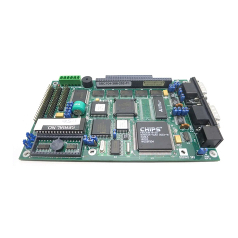
The AIM10 -386EX is a single board computer with the PC/10 form factor, based on the Intel 386EX
processor. On-board peripheral functions include four COM channels, a real time clock and an event
timer/watchdog timer. The event timer can trigger periodic recovery from power down mode, allowing low
average current consumption. The Director operating system periodically services the watchdog timer. In
case of software failure or lockup, system reset will occur when the watchdog times out.
The AIM10 -386EX offers a 25 MHz processor board, running a multi-tasking software kernel. To function
correctly, the processor needs the correct boot files in addition to valid configuration files which are stored in
its Flash Filing System. AIM10 -386EX has four serial ports, COM0 through COM3, with COM3
configurable through link settings for RS-232 or RS- 85/ 22 operation.
An enhanced 5V monitor/reset provides brown-out protection. A FLASH device provides permanent storage
for Director operating system, configuration files, and programming. A hardware Real-time Clock (RTC)
device is provided.
4.3.1 AIM104-386EX Link Settin s
The following diagram shows the necessary link settings on the AIM10 -386EX for it to operate properly
within a Director system. Shaded links indicate jumpers which are fitted.
B LK9 A
B LK10 A
B LK7 A
B LK8 A
B LK5 A
B LK6 A
C LK4 A C LK2 A
C LK3 A LK1
PL2
TP3
FT1
FT2
PL1
TP7
LK17
PL6
LK16
TP1
TP2
TP4
TP5
PL3
PL7
PL5
PL4
TP6
Drg. S15040-04a

DS2/DS4 Hardware Manual
Page 13
4.3.2 SCT-AIM104 Link Settin s
When used in a Director, a few jumpers are necessary on the SCT-AIM10 baseboard for proper use with
certain I/O boards. These links are located on the bottom of the PC/10 pins, and connect certain IRQ lines
together on the processor card. The pins are on the outer set of pins for the shorter section of the PC/10
header. Certain cards used in the Director were built to operate with a certain IRQ, but those IRQs were not
available on the AIM10 -386EX processor.
AIM10 -Ether: Board uses IRQ15, but 386EX uses IRQ1
AIM10 -COM : Last COM port uses IRQ11, but 386EX uses IRQ12
PL5 PL4
Front row PC/104
pins (D0)
Connects IRQ11 to IRQ12 Connects IRQ14 to IRQ15
Drg. S15040-04b
Other important jumpers on the SCT-AIM10 baseboard select COM3 to be RS-232 or RS- 85, and
enable/disable the on-board battery. The links JP1-JP are located at the back of the baseboard and should all
be moved to either the “RS232” or “RS 85”, and JP5 is located next to the battery.
JP1
JP2
RS232 COM3 in RS-232 mode.
JP3
JP
RS 85 COM3 in 2-wire RS- 85 mode.
JP5 Removed Battery backup disabled. When removed, the real-time clock will
not be maintained after power is removed. This is the default
position.
Fitted Battery backup enabled. When fitted, the real-time clock is
maintained after power is removed.

DS2/DS4 Hardware Manual
Page 14
4.3.3 RS-232 Serial Interface: COM0 to COM3
Four 9-way 'D' type connectors (DB-9) for COM0 through COM3 are located on the front of the Director
enclosure from the SCT-AIM10 board, which receives its signals via a 50-way ribbon cable to the AIM10 -
386EX. SCT-AIM10 links JP1-JP must be in the “RS232” position.
The pin-out of the DB-9 serial interface for RS-232 is presented as follows:
* = output signals from processor
DB-9 Male
DB-9
2 RX
3 TX*
5 GND
7 RTS*
8 CTS
4 DTR*
1 DCD
6 DSR
RS-232 Pinouts (DTE)
1 2 3 4 5
6 7 8 9
Drg. S15037-04a
The direction of data with respect to the Director serial interface is such that the Director acts as a DTE (Data
Terminal Equipment) device. This means:
TX is used to transmit data from the Director.
RX is used by the Director to receive data.
GND must be connected to an RS-232 GND on the other device for proper communication.
RTS is asserted prior to the Director sending data.
CTS must be received before data will be transmitted (a jumper from RTS may be used, if
no handshaking lines are required for a modem).
DTR is asserted to indicate the Director is ready to receive data.
DCD must be received before incoming data will be accepted (a jumper from DTR may be
used, if no handshaking lines are required for a modem).

DS2/DS4 Hardware Manual
Page 15
4.3.4 RS-485 Serial Interface: COM3
The last serial port on the DS2/DS (COM3) may be optionally configured for either RS-232 or RS- 85
communication. SCT-AIM10 links JP1-JP must be in the “RS 85” position to operate in this mode.
The RS- 85 communication port is optically isolated. When COM3 on the Director is configured for two-
wire RS- 85 operation, up to 32 devices can be connected together in a multidrop fashion. The following pin
configuration is used:
DS-2, DS-3, DS-4 COM3 port
DB-9M (jumpers must be set
internally for RS-485)
11
6
5 GND
RS-485 TX -
RS-485 TX
For DS-2/4, JP1 on SCT-AIM104 must
be set to the "RS-485" position.
For DS-3, LK2 on SCT-ORBCOMM
must be set to A, and LK3 must be B.
Drg. S15037-01d
RS- 85 is a balanced differential system, in which the voltage produced by the driver appears across a pair of
signal lines that transmit only one signal. A balanced line driver produces a voltage from 2 to 6 volts across
its positive and negative output terminals. A balanced differential line receiver senses the voltage state of the
transmission line across the two signal input lines.
Data + is connected to the Data + of other 2-wire RS- 85 devices.
Data - is connected to the Data - of other 2-wire RS- 85 devices.
GND should be connected to signal ground at one end of the cable network for grounding
cable shield, not used by a balanced line receiver in determining the logic state of the
data line.
4.3.5 RS-485 / RS-422 Wirin Dia rams
When connecting RS- 85 or RS- 22 devices in a multidrop configuration, there must usually be a 120Ω
termination resistor on the first and last devices in the network, but not on any devices in the middle of the
loop.
In RS- 85 or RS- 22 systems, the ground connection is optional. It is typically used to connect the cable
shield for a shielded, twisted pair cable. In the DS2/DS COM3 port, the RS- 85/ 22 ground is common with
the RS-232 grounds, but is isolated from the metal case. In order to avoid ground loops, connect the cable
shield to the RS- 85/ 22 GND at only one point in the network.

DS2/DS4 Hardware Manual
Page 16
1st Device
Middle
Device(s) End Device
TX
TX-
GND
TX
TX-
TX
TX-
2-wire RS-485 Device Connections
End devices usually need 120 ohm termination resistor,
optional middle device(s) must not have resistor.
Master Device
Middle
Device(s) End Device
TX
TX-
RX
RX-
GND
RX
RX-
TX
TX-
4-wire RS-485/422 Device Connections
End device (and RS-485 Master) may need 120 ohm termination
resistor, optional middle device(s) must not have resistor.
Drawing is labeled as if devices are DTE. Direction of arrows is
correct, regardless of RX/TX labeling on a given device.
RX
RX-
TX
TX-
Drg. S15037-02
(Optional)
(Optional)

DS2/DS4 Hardware Manual
Page 17
5 Optional I/O Boards
On-board serial ports provide four serial communication channels. Optional PC/10 boards are available to
provide additional communication ports and other I/O for certain applications. This chapter describes the
connections and configuration of these boards.
5.1 AIM104–Ether Ethernet Interface
The AIM10 -Ether board provides an IEEE 802.3 interface and is used to download the configuration files to
the DS2/DS unit, and provides the Ethernet network interface.
5.1.1 AIM104 Ether Link Settin s
Link LK1 should be set to the B position, and LK2 should be fitted as default.
All other configuration required such as base address, 2 0H (576 Decimal) and interrupt settings (IRQ1 ) are
pre-programmed as a software configuration in the EEPROM.
Note: If the AIM10 Ether board is fitted, ensure the additional jumper is fitted on the PC/10 pins,
to connect IRQ1 to IRQ15. See Section .3.2 for details.
The Ethernet port of the DS2/DS provides network capability via an RJ- 5 10baseT connector. In order for
the Director software to recognize the Ethernet adapter, it must be configured for the correct base address and
IRQ of the Ethernet controller. This is typically done via the ACE (Arcom Configuration Environment)
configuration program. The Address and IRQ settings are also used when selecting Ethernet as the mode of
operation for the Bootloader menu (see Startup Manual).
Ethernet Settin s Required for DS2/DS4 Confi uration:
Network Card Address: 576
Network Card IRQ: 1
Network Card DPMA: 851968 (unused)

DS2/DS4 Hardware Manual
Page 18
5.2 AIM104-SER4 Serial Interface
This section describes the use of the AIM10 -SER serial communications board. All baud rates, parity, stop
bits and data bits are configured using the ACE configuration tool. Every channel may be configured
independently. Maximum baud rate is 57.6 kbaud.
The AIM10 -SER has a 50-way connector which connects via a 50-way ribbon cable to four 9 way ‘D’ type
connectors mounted on the rear panel of the DS .
5.2.1 AIM104-SER4 Specifications
The AIM10 -SER requires +5 and ±12 VDC supply, which is a factory fit option. Some Director
baseboards include a factory fit power supply which only provides +5 VDC, which will not run the AIM10 -
SER .
Serial Controller 85230
Number of Inputs Four RS-232
Power 2.55 Watt (max)
Operatin Temperature -20 to +70C
5.2.2 SER4 Link Settin s – 1st card
Below are the link settings for an AIM10 -SER to configure it for the first bank of COM ports. These ports
are COM through COM 7 on the DS .
LK1
LK3
LK4
LK2
E D C B A
A4
A5
A6
A7
A8
A9
LK5
F
E
D
C
B
A
LK6
F
E
D
C
B
A
NOTE: Link LK3 should be fitted on the first AIM10 -SER if a second SER card is used.

DS2/DS4 Hardware Manual
Page 19
5.2.3 SER4 Link Settin s – 2nd Card
Below are the link settings for an AIM10 -SER to configure it for the second bank of COM ports. These
will be COM 8 through COM 11 on the DS .
LK1
LK3
LK4
LK2
E D C B A
A4
A5
A6
A7
A8
A9
LK5
F
E
D
C
B
A
LK6
F
E
D
C
B
A

DS2/DS4 Hardware Manual
Page 20
5.2.4 Si nal Interface to 9 way ‘D’ type connectors
The DS has a few optional rear plates that provide four or eight 9-way 'D' type connectors (DB-9) which may
plug directly into the 50-way termination on the AIM10 -SER .
The pin-out of the DB-9 serial interface is presented as follows:
The direction of data with respect to the DS is such that the DS acts as a DTE device. This means:
TX is used to transmit data from the DS .
RX is used by the DS to receive data.
GND must be connected to an RS-232 GND on the other device for proper communication.
RTS is asserted prior to the DS sending data.
CTS must be received before data will be transmitted (a jumper from RTS may be used, if
no handshaking lines are required for a modem).
DTR is asserted to indicate the DS is ready to receive data.
DCD must be received before incoming data will be accepted (a jumper from DTR may be
used, if no handshaking lines are required for a modem).
This manual suits for next models
1
Table of contents
Other Arcom Computer Hardware manuals
Popular Computer Hardware manuals by other brands

Delta Electronics
Delta Electronics SIW75 Series SIW75 Product specifications
Juniper
Juniper SSG140 Hardware installation and configuration guide
Digi
Digi ConnectCore 6UL Hardware Design Guidelines
Lindy
Lindy CPU SWITCH LITE 32825 user manual

evertz
evertz 3067VIP10G-3G-HW user manual

Renco
Renco Prelos manual
