Arcom SBC104 User manual

Page 1
2192-08704-000-000J562 SBC104
Arcom - SBC104
EEmmbbeeddddeedd
PPCC
CCoommppaattiibbllee
CCPPUU
BBooaarrdd
TTeecchhnniiccaall
MMaannuuaall
Product Information
Full information about other Arcom products is available via the FFaaxx--oonn--DDeemmaanndd
SSyysstteemm, (Telephone
Numbers are listed below), or by contacting our WWeebbSSiitteein the UK at: wwwwww..aarrccoomm..ccoo..uukk, or in the US
at: wwwwww..aarrccoommccoonnttrroollss..ccoomm
UUsseeffuull
CCoonnttaacctt
IInnffoorrmmaattiioonn
UUsseeffuull
CCoonnttaacctt
IInnffoorrmmaattiioonn
CCuussttoommeerr
SSuuppppoorrtt
--
UUKKSSaalleess
OOrrddeerr
DDeesskk
--
UUKKTTeecchhnniiccaall
SSaalleess
--
UUKK
Tel: +44 (0)1223 412 428 Tel: o800 411 200 Tel: 0800 411 300
Tel: +44 (0)1223 413 028 Tel: +44 (0)1223 413 028 Tel: +44 (0)1223 413 036
Fax: +44 (0)1223 403 400 Fax: +44 (0)1223 410 457 Fax: +44 (0)1223 410 457
UUnniitteedd
KKiinnggddoomm
Arcom Control Systems Ltd
Clifton Road
Cambridge CB1 4WH, UK
Tel: 01223 411 200
Fax: 01223 410 457
FoD: 01223 240 600
UUnniitteedd
SSttaatteess
Arcom Control Systems Inc
13510 South Oak Street
Kansas City MO 64145 USA
Tel: 816 941 7025
Fax: 816 941 0343
FoD: 800 747 1097
FFrraannccee
Arcom Control Systems
Centre daffaires SCALDY
23 rue Colbert
7885 SAINT QUENTIN
Cedex, FRANCE
Tel: 800 90 84 06
Fax: 800 90 84 12
FoD: 800 90 23 80
GGeerrmmaannyy
Kostenlose Infoline:
Tel: 0130 824 511
Fax: 0130 824 512
FoD: 0130 860 449
IIttaallyy
NumeroVerde:
FoD: 1678 73600
BBeellggiiuumm
Groen Nummer:
Tel: 0800 7 3192
Fax: 0800 7 3191
NNeetthheerrllaannddss
Gratis 06 Nummer:
Tel: 06022 11 36
Fax: 06022 11 48
The choice of boards or systems is the responsibility of the buyer, and the use to which they are put cannot be
the liability of Arcom Control Systems Ltd. However, Arcoms sales team is always available to assist you in
making your decision.
© 1997 Arcom Control Systems Ltd
Arcom Control Systems is a subsidiary of Fairey Group Plc.
Specifications are subject to change without notice and do not form part of any contract.
All trademarks recognised.
Arcoms board
production facilities
are fully compliant
with ISO 9002

Warning
Handling
This board contains static sensitive devices. Observe anti-static precautions at all times. Unpacking
and installation of the board should be undertaken in an anti-static working area.
Battery
Note: The board is supplied with the battery supply isolated. Move Link 3 to position A before using
the board.
The board is fitted with a Nickel Metal Hydride rechargeable battery. Do not short circuit the battery
or place the board on a metal surface where the battery terminals could be shorted.
Dispose of the battery with care. Do not incinerate, crush or other wise damage the battery.
Electromagnetic Compatibility (EMC)
The SBC104 is classified as a component with regard to the European Community EMC regulations
and it is the users responsibility to ensure that systems using the board are compliant with the
appropriate EMC standards. Arcom can offer an EMC CE compliant solution if the SBC104 is used as
part of the ACE (Arcom Compact Enclosure) product.
Acknowledgements
Arcom Flash Filing System (AFFS), is the generic name given to the ported Flash Filing System called
CardTrick.
Both CardTrick and ROM-DOS 6.22 are trademarks of Datalight Inc
. Each SBC104
Includes two small license labels to identify the installed Datalight product. Do not remove.
2192-08704-000-000
Page 2
J562 SBC104
Manual
Issue A
Issue B
Issue C
Issue D
V1 Iss2
V1 Iss2
V1 Iss2
V2 Iss2
961122 First full release of Manual
970107 Minor edits throughout Manual
970227 Inclusion of ROM-DOS 6.22
971022 [ECO2614, 2649]
PCB Comments
Revision History

Contents
Revision History . . . . . . . . . . . . . . . . . . . . . . . . . . . . . . . . . . . . . . . . . . . . . . . . . . . . . . . . . . . . . . . . . . . . . 2
Introduction . . . . . . . . . . . . . . . . . . . . . . . . . . . . . . . . . . . . . . . . . . . . . . . . . . . . . . . . . . . . . . . . . . . . . . . . 5
Features . . . . . . . . . . . . . . . . . . . . . . . . . . . . . . . . . . . . . . . . . . . . . . . . . . . . . . . . . . . . . . . . . . . . . . 5
Getting Started with the SBC104 . . . . . . . . . . . . . . . . . . . . . . . . . . . . . . . . . . . . . . . . . . . . . . . . . . . . . . . . 7
How the SBC104 works . . . . . . . . . . . . . . . . . . . . . . . . . . . . . . . . . . . . . . . . . . . . . . . . . . . . . . . . . . 7
Before Powering up the board . . . . . . . . . . . . . . . . . . . . . . . . . . . . . . . . . . . . . . . . . . . . . . . . . . . . 7
Switching On . . . . . . . . . . . . . . . . . . . . . . . . . . . . . . . . . . . . . . . . . . . . . . . . . . . . . . . . . . . . . . . . . . . 7
Links and Options . . . . . . . . . . . . . . . . . . . . . . . . . . . . . . . . . . . . . . . . . . . . . . . . . . . . . . . . . . . . . . . . . . . . 9
Link Configuration . . . . . . . . . . . . . . . . . . . . . . . . . . . . . . . . . . . . . . . . . . . . . . . . . . . . . . . . . . . . . . 9
User Configuration Diagram . . . . . . . . . . . . . . . . . . . . . . . . . . . . . . . . . . . . . . . . . . . . . . . . . . . . . . . 10
EMC Chassis Point . . . . . . . . . . . . . . . . . . . . . . . . . . . . . . . . . . . . . . . . . . . . . . . . . . . . . . . . . . . . . . 10
Using the SBC104 . . . . . . . . . . . . . . . . . . . . . . . . . . . . . . . . . . . . . . . . . . . . . . . . . . . . . . . . . . . . . . . . . . . . 11
Getting Started . . . . . . . . . . . . . . . . . . . . . . . . . . . . . . . . . . . . . . . . . . . . . . . . . . . . . . . . . . . . . . . . . 11
Setting up the SBC104 for a PC/104 VGA card and Keyboard . . . . . . . . . . . . . . . . . . . . . . . . . . . . . 11
Setting up the SBC104 for Remote mode . . . . . . . . . . . . . . . . . . . . . . . . . . . . . . . . . . . . . . . . . . . . 11
Using the SBC104 in Remote Mode . . . . . . . . . . . . . . . . . . . . . . . . . . . . . . . . . . . . . . . . . . . . . . . . . 12
ROM-DOS Remote Disk . . . . . . . . . . . . . . . . . . . . . . . . . . . . . . . . . . . . . . . . . . . . . . . . . . . . . . . . . . 12
Borland C Turbo Debug Remote . . . . . . . . . . . . . . . . . . . . . . . . . . . . . . . . . . . . . . . . . . . . . . . . . . . . 13
Memory Map . . . . . . . . . . . . . . . . . . . . . . . . . . . . . . . . . . . . . . . . . . . . . . . . . . . . . . . . . . . . . . . . . . . . . . . . 15
I/O Map . . . . . . . . . . . . . . . . . . . . . . . . . . . . . . . . . . . . . . . . . . . . . . . . . . . . . . . . . . . . . . . . . . . . . . . . . . . . 15
Special Function Registers . . . . . . . . . . . . . . . . . . . . . . . . . . . . . . . . . . . . . . . . . . . . . . . . . . . . . . . . . . . . . 16
Additional On-Board Features . . . . . . . . . . . . . . . . . . . . . . . . . . . . . . . . . . . . . . . . . . . . . . . . . . . . . . . . . . 19
User Link . . . . . . . . . . . . . . . . . . . . . . . . . . . . . . . . . . . . . . . . . . . . . . . . . . . . . . . . . . . . . . . . . . . . . . 19
Status LEDs . . . . . . . . . . . . . . . . . . . . . . . . . . . . . . . . . . . . . . . . . . . . . . . . . . . . . . . . . . . . . . . . . . . . 19
Watchdog Timer . . . . . . . . . . . . . . . . . . . . . . . . . . . . . . . . . . . . . . . . . . . . . . . . . . . . . . . . . . . . . . . . 19
System BIOS . . . . . . . . . . . . . . . . . . . . . . . . . . . . . . . . . . . . . . . . . . . . . . . . . . . . . . . . . . . . . . . . . . . 19
SRAM . . . . . . . . . . . . . . . . . . . . . . . . . . . . . . . . . . . . . . . . . . . . . . . . . . . . . . . . . . . . . . . . . . . . . . . . 19
RS-485 . . . . . . . . . . . . . . . . . . . . . . . . . . . . . . . . . . . . . . . . . . . . . . . . . . . . . . . . . . . . . . . . . . . . . . . 19
The SBC104 Utilities Disk . . . . . . . . . . . . . . . . . . . . . . . . . . . . . . . . . . . . . . . . . . . . . . . . . . . . . . . . . 19
SAVECMOS Utility . . . . . . . . . . . . . . . . . . . . . . . . . . . . . . . . . . . . . . . . . . . . . . . . . . . . . . . . . . . . . . . 20
Appendix A. Connections . . . . . . . . . . . . . . . . . . . . . . . . . . . . . . . . . . . . . . . . . . . . . . . . . . . . . . . . . . . . . . 21
Appendix B. Disabling the On-board Flash . . . . . . . . . . . . . . . . . . . . . . . . . . . . . . . . . . . . . . . . . . . . . . . . 25
Appendix C. Reference . . . . . . . . . . . . . . . . . . . . . . . . . . . . . . . . . . . . . . . . . . . . . . . . . . . . . . . . . . . . . . . . 27
Audible Signals . . . . . . . . . . . . . . . . . . . . . . . . . . . . . . . . . . . . . . . . . . . . . . . . . . . . . . . . . . . . . . . . . 27
Appendix D. Circuit Diagrams . . . . . . . . . . . . . . . . . . . . . . . . . . . . . . . . . . . . . . . . . . . . . . . . . . . . . . . . . . . 29
Page 3
2192-08704-000-000J562 SBC104

2192-08704-000-000
Page 4
J562 SBC104

Introduction
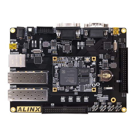
The SBC104 is a PC-compatible 386SX/486SXLC processor board supporting a 16-bit PC/104
interface which combined with a PC/104 VGA CRT/Flat Panel display module can form the complete
DOS compatible PC for embedded applications. The board is fitted with 2 or 4 Mbytes of DRAM, 1 or
2 Mbytes of FlashFilememory and optionally 128 Kbyte of battery backed SRAM. Systems BIOS
and extensions are contained in a 128 Kbyte EPROM. Onboard peripheral ports include COM1 and
COM2, a floppy disk controller, hard disk (IDE) controller, a parallel port (LPT1) and keyboard
interface.
The board is available in the following variants:
SBC104-386-252-F1 - 386SX processor, 2 Mbyte DRAM and 1 Mbyte Flash memory
SBC104-386-254-F2 - 386SX processor, 4 Mbyte DRAM and 2 Mbyte Flash memory
SBC104-486-504-F2 - 486SXLC processor, 4 Mbyte DRAM and 2 Mbyte Flash memory
Features
25MHz 80836SX or 50MHz TI 486SXLC2 processor
TI486SXLC2 contains 8 Kbyte of internal cache
PC-AT architecture
2 or 4 Mbytes of DRAM
1 or 2 Mbytes of FlashFilememory
Includes Arcom Flash Filing System
Includes ROM-DOS 6.22
Optional 128 Kbyte of battery backed SRAM
Battery backed Real Time Clock
FDD interface via vertical 34-way header
HDD IDE interface via vertical 40-way header
LPT parallel port via vertical 26-way header
COM1 & COM2 RS232 serial ports via individual 9-way D-type plugs
Link selectable half- duplex RS-485 available on COM2
AT keyboard interface via a 6-way Mini DIN socket
Mini Buzzer for audible alarm
Watchdog timer generating an NMI or optional reset (3 second time-out)
PC/104 Interface, 16-bit, single Master only
11mAHr Ni-MH battery: Full charge time = 70 hours
Hold-up time = 550 hours
Battery life = 6 years @ 25°C
Operating temperature range : 338866SSXX
+5°C to 65°C (with battery fitted)
-20°C to +70°C (without battery fitted)
448866SSXXLLCC
+5°C to 50°C (with battery fitted)
-20°C to +50°C (without battery fitted)
Power Consumption: @ +5v 700mA
MTBF (using generic figures from MIL-HDBK-217F at ground benign): 152,240 hours
Single Eurocard form factor
EMC Chassis connection point
Status LEDs for Flash drive access and Processor running
Single User Link
Arcom also manufactures a range of PC/104 modules for use with the SBC104. These include
optoisolated digital and analogue I/O, VGA controller, relay output, CAN interface, multi-port serial
communications and ethernet.
Page 5
2192-08704-000-000J562 SBC104

2192-08704-000-000
Page 6
J562 SBC104

Getting Started with the SBC104
How the SBC104 works
The SBC104 is a PC-compatible processor board. There are connections on the SBC104 for a
keyboard, floppy drive, a hard drive, two serial communication ports and a centronics parallel port.
There is also a PC/104 connector that will allow you to connect a PC/104 VGA board to form a
complete PC system environment.
The SBC104 board is supplied with Arcom Flash Filling System (AFFS) and ROM-DOS 6.22 pre-
loaded. ROM-DOS is a flexible, small and fast compatible DOS. More information on the differences
between ROM-DOS and the DOS standard can be found on the utilities disk under
A:\DOC\ROMDOS.DOC.
Using AFFS the on-board Flash memory appears exactly as a normal hard drive interface. All the
application software can be loaded onto the Flash and run exactly as if it were a standard hard drive.
There is no need to configure the on-board Flash memory in the BIOS set-up utility as the AFFS will
automatically configure the Flash as the C:\ drive. Any additional drives connected to the IDE
connector will be allocated as the next drive up (i.e. the D:\ drive). The on-board Flash can be
disabled for applications which are intended to have an external IDE drive as the C:\ drive (see
appendix on disabling the on-board Flash).
The SBC104 can be used either with or without a VGA/Keyboard interface. The SBC104 is factory
loaded with a simple AUTOEXEC.BAT file and a small program FINDVGA.EXE that detects the
presence of VGA card. If there is a VGA card fitted then the SBC104 can be used as exactly as any
PC. If there is no VGA card fitted then the SBC104 will re-direct output to the serial port COM1 which
should be connected to a PC terminal emulator or a PC with a windows terminal emulator. This kind
of operation is referred to as Remote Mode.
Before Powering up the board
Connect a +5v power supply to the power header PL5. The SBC104 does nnoottrequire ±12v to operate
so if any of the PC/104 boards connected to the SBC104 require a +12v or -12v power supply (such
as the AIM104-SER4) then connect these to PL5. Refer to the labelling on the board and the
appendix for the correct connections.
Battery back-up is necessary to maintain the CMOS BIOS settings. If a battery back-up voltage is not
present then the SBC104 will revert to its default settings. The battery link LK3 is isolated on the
SBC104 during shipment. Move LK3 to position A to enable the battery backup facility. If battery
backup is to be supplied from an external source instead of the on-board battery then connect
positive voltage from the backup supply (which must be +3.7) to +VBB and the ground to GND on
PL5. In this case LK3 should be removed completely.
Switching On
As the battery link has been removed during shipment the CMOS RAM may be corrupted and the
board will either need to be reconfigured or it will reset to its default CMOS settings These default
settings configure the SBC104 for a single floppy drive. To reconfigure the board to accept another
floppy or a hard drive then it is necessary to connect a PC/104 VGA board and a keyboard in order
to alter the parameters within the SET-UP utility (see appendix on configuring drives.).
Note: Even in this default configuration the SBC104 will boot successfully without a keyboard, floppy
or hard drive connected. There will, however, be an error message on boot-up that will indicate that
drive a:\ is not configured correctly.
Page 7
2192-08704-000-000J562 SBC104

2192-08704-000-000
Page 8
J562 SBC104

Links and Options
Link Configuration
Page 9
2192-08704-000-000J562 SBC104
LK15
COM1
EMC Chassis Point
RESET
IDE LED
IDE Connector
Floppy Disk Connector
Printer Port
RUN LED
Power Connector
SRAM
BIOS
PC/104 INTERFACE
Keyboard
Flash Access LED
COM2
LK5
LK6
A LK13 B
A LK14 B
PL8
PL9
PL5
PL10 PL4
PL7
PL1
PL2
PL3
LK12
LK11
LK10
LK9
LK3 A LK1
LK2
LK7 A
LK8 A
B
B
B
LK1
LK2
LK3
LK4
LK5
LK7 & 8
LK9, 11 & 12
IRQ4 Source Select
If fitted, interrupt IRQ4 will be enabled to work from COM1 and PC/104
If omitted IRQ4 will work solely from the PC/104 bus
IRQ3 Source Select
If fitted, interrupt IRQ3 will be enabled to work from COM2 and PC/104
If omitted IRQ3 will work solely from the PC/104 bus
Battery back-up link
Position A = Connected
Position B = Isolated
Note: If battery back-up is provided via the +VBB connection on PL5 then this link should be
omitted.
Factory Fit only - Do Not Change
Watchdog time-out Selection
If fitted a Watchdog time-out will cause a hardware reset.
If omitted a Watchdog time-out will cause an NMI.
Floppy Disk Drive Configuration Links
Position A = Drives that do not require a twisted cable
Position B = Drives that do require twisted cable
(See appendix on Drive Connections).
COM2 RS232/RS-485 Configuration Links
If fitted COM2 operates in RS-485
If omitted COM2 operated in RS232

2192-08704-000-000
Page 10
J562 SBC104
LK10
LK6, 13 & 14
RS-485 Termination Resistor Link
If fitted RS-485 on COM2 is terminated by a 120Ωresistor
If omitted resistor is isolated
Factory Fit Only - Do Not Change
(Continued from previous page)
EMC Chassis Point
The SBC104 has a clearly labelled EMC chassis point near the keyboard connector. This point serves
as a mounting hole for the PC/104 stack through modules. It should be connected to the earth point
of the enclosure.
User Configuration Diagram
LK15
COM1
COM2
LK5
LK6
A LK13 B
A LK14 B
PL8
PL9
PL5
PL10 PL4
PL7
PL1
PL2
PL3
LK12
LK11
LK10
LK9
LK3 A LK1
LK2
LK7 A
LK8 A
B
B
B

Using the SBC104
Getting Started
Please ensure that you have read the Getting Started section of this manual as it contains important
information that should be used in conjunction with this section.
Setting up the SBC104 for a PC/104 VGA card and Keyboard.
1. Connect a standard PC keyboard to the PS/2 keyboard socket SK3.
2. Plug a PC/104 VGA or CRT/Flat panel interface board into the PC/104 stack connector. The SBC104
will work with either 8-bit or 16-bit cards.
3. If required connect a floppy drive to PL4, a hard drive to PL3 and any parallel device to PL10. Make
sure that the cables are connected the right way round (see appendix for connections).
4. Turn the power on. The BIOS SETUP utility can be entered during the boot process by pressing
Ctrl-Alt-S when prompted. Once in SETUP various parameters can be configured. To change a
parameter use the arrow keys to highlight the relevant section and then use the space bar to scroll
through the available options. To save the settings and exit press F10. To exit without saving the
new parameters press ESC. For standard operation of the SBC104 the only usual changes that have
to made are to the time and date, floppy and hard drive parameters.
Altering some of the advanced CMOS BIOS parameters may cause the SBC104 to work incorrectly.
To reset to the default settings turn off the power to the SBC104 and move LK3 to position B for a
few seconds. Then replace LK3 in position A.
6. Once the SBC104 has beeped to confirm that all the BIOS hardware checks have been completed
successfully, the SBC104 will run the pre-installed AUTOEXEC.BAT file and FINDVGA.EXE from the on-
board FlashFilememory which will check to see if there is VGA card present. Once this is done the
SBC104 will display a message saying VGA FOUND and then return C:\ prompt. The SBC104 has now
successfully booted.
Setting up the SBC104 for Remote mode
1. A null modem cable should be connected between the COM1 D-type connector on the SBC104 and
a free COM port on the PC. The cable should configured as follows:
Page 11
2192-08704-000-000J562 SBC104
SBC104
9-way
1
2
3
4
5
6
7
8
9
nc
3
2
6
5
4
8
7
nc
nc
3
2
6
7
20
5
4
nc
PC/Terminal
9-way
PC/Terminal
25-way

2. The output from the SBC104 needs to be re-directed to the serial port COM1. The board is pre-
fitted with a simple AUTOEXEC.BAT file that calls FINDVGA.EXE which will default to COM1 if a PC/104
VGA card is not detected. These files can be found on the utilities disk under
A:\INSTALL\AUTOEXEC.BAT. The SBC104 will configure COM1 to the settings below:
Baudrate 9600
Parity none
Bits 8
Stop 1
3. To communicate with the SBC104 through this serial link a terminal emulator window should be
opened on the host PC and set to the above settings. In Windows 3.11 use the terminal icon. In
Windows 95 use the hyper terminal. The terminal emulator window should be set to the PC serial
communications port that the null modem cable is connected to.
4. Turn on the SBC104. The Flash Access LED will Flash intermittently to show that the FlashFile
memory is being accessed as the SBC104 boots. After approximately thirty seconds the message
below should appear in your terminal window:
CHIPS SCATsx/PEAKsx BIOS Version 3.04.a
Decompilation or Disassembly Prohibited
Copyright Arcom Control Systems Ltd.
SBC104 Version 1.1
Copyright (c) Chips and Technologies, Inc,.All Rights Reserved
C:\
Note: Once you have reached the c:\ prompt the installed files shown below can be deleted if
necessary. This will allow the SBC104 to boot straight to the C:\ prompt on future occasions without
checking for a VGA card and then possibly re-directing the output to the serial port COM1. These
pre-installed files can be found on the utilities disk in the a:\install directory. When the SBC104
is booted from the utilities disk you are given the option of re-installing these files or re-installing
AFFS and ROM-DOS. This can be done in remote mode through a terminal emulator as the utilities
disk also scans for VGA card and re-directs output to COM1 if there is no VGA Card connected.
Using the SBC104 in remote mode.
The SBC104 can be used with no VGA card or keyboard connected in remote mode as described
earlier. But when developing software for the SBC104 there is still the problem of loading it onto the
on-board Flash. The most practical way of doing this is to connect a floppy drive to the SBC104 and
copy files to the Flash via commands in a terminal emulator window. This can be slow if there are
many files to be copied. An alternative to this is to use the ROM-DOS remote disk utility to copy files
onto the SBC104 FlashFilememory and a remote debugging facility to evaluate the application
software.
ROM-DOS Remote-Disk
The ROM-DOS Remote Disk Utility program allows you to access the SBC104 on-board FlashFile
memory as a logical disk drive on a client desktop PC. This allows you to edit and copy files between
the host system and the SBC104 as if it were just another hard drive. The SBC104s FlashFile
memory drive will appear as the next available drive letter (e.g. D:\).
2192-08704-000-000
Page 12
J562 SBC104

In remote disk setup, the SBC104, which is sharing its c:\ drive, is termed the Server. The other
system, the PC that will access and use the remote drives, is called the client.
Below are brief guidelines on using ROM-DOS Remote Disk. Run the file A:\DOCS\RDUSER.EXE
from the utilities disk to obtain the full manual text.
Using ROM-DOS Remote Disk with Windows 3.11
1. Create a directory on your hard disk called REMDISK. Copy the files REMDISK.EXE and
REMQUIT.EXE from the utilities disk to this directory.
2. Add the line DEVICE=C:\REMDISK\REMDISK.EXE /b9600 /comN to the CONFIG.SYS file. Where
N is the COM port that the null modem cable is connected to. This will cause the client PC to
assign a drive for the SBC104 Flash memory. Turn off the client PC.
3. Complete the above section on Setting up the SBC104 in Remote Mode.
4. At the c:\ prompt in the terminal window, type: REMSERV c: /b9600 /com1. This will configure
the SBC104 on-board Flash for remote access. As the SBC104 is now running REMSERV it can not
be accessed through the terminal window until the Remote Disk utility is terminated.
5. Open the file manager and the SBC104 FlashFile memory should appear as the D:\ drive or the
next available drive.
6. To terminate the remote disk utility open a MS-DOS window and type: REMQUIT. This will free
the SBC104 from running REMSERV and allow you to run programs on the SBC104 using the
terminal window.
Using ROM-DOS Remote Disk with Windows 95
Windows 95 differs from Windows 3.11 in the manner in which it controls the COMs ports. This can
lead to the Remote Disk utility working incorrectly. To avoid this, follow the steps below exactly:
1. Follow steps 1-4 on how to use Remote disk with Windows 3.11
2. Close the Hyper terminal window as Windows 95 will not let two applications share a COM port.
3. Open Windows Explorer. The SBC104 should appear as Removable Disk [D:] or the next available
drive letter.
4. To terminate the Remote Disk utility the SBC104 must be re-booted. (REMQUIT does not work.)
Borland C Turbo Debug Remote
The Borland C Turbo Debug Remote facility is the most appropriate for developing code. It requires
the SBC104 to be loaded with the file TDREMOTE.EXE. After this the application code can be loaded
via the serial link and run on the SBC104 within the familiar Turbo debug environment.
If you are developing using BORLAND C, the SBC104 can be used in remote mode using the
TDREMOTE.EXE utility. To use this program you will require a NULL MODEM cable (as described
earlier). Copy the program TDREMOTE.EXE from your BORLANDC\BIN directory to your SBC104. You
can use the ROM-DOS remote disk utility mentioned above. Add the following command to the
AUTOEXEC.BAT of your SBC104 ( or type it at the DOS prompt). If you have placed this in you
AUTOEXEC.BAT you will need to reboot.
TDREMOTE -rpX -rsN
-: where XXis the COM port to use (default is COM1) and where NNis the baud rate to use. This is
specified as :
-rs1 Slowest speed, 9600 baud.
-rs2 Slow speed, 19,200 baud.
-rs3 Medium speed, 38,400 baud.
-rs4 Fastest speed, 115,000 baud (default)
Page 13
2192-08704-000-000J562 SBC104

As an example, the following command will configure COM2 for remote communication at 38,400
baud :
TDREMOTE -rp2 -rs3
The SBC104 is now ready to receive the application. Next, we set up the host system. The host
system will be you development PC that contains the compiler/ debugger and the application that
you are developing for the SBC104. Type the following at the DOS prompt :
TD -rpX -rsN AppName
Again the X refers to the COM channel on the PC that is used and the N refers to the serial link speed.
Please note that the link speed set here MUST be the same as that set up on the SBC104. The
parameter AAppppNNaammeerefers to the application name (the .EXE name). When you have done this you
will see the familiar TURBO DEBUGGER screen. You can now debug your application remotely as it
is running on the SBC104.
NOTE: Full details of Remote Debugging can be found in the BORLAND manuals or in the Borland
HELP files.
2192-08704-000-000
Page 14
J562 SBC104

Memory Map
When adding boards or software memory managers it is important that they are configured so that
they do not contend or interfere with the on-board memory devices.
I/O Map
Page 15
2192-08704-000-000J562 SBC104

Special Function Registers
Flash Memory (258h,259h) - Write Only
These registers are cleared at reset. These registers are normally accessed by the Arcom Flash Filing
System. This information is included for reference only.
258h
259h
SRAM Memory (94h) - Write Only
This register is cleared at reset. These registers are used by SRAMDISK.SYS.
Watchdog Timer (93h) - Write Only
Writing to this address will trigger the watchdog timer. This must be re-triggered within 3 seconds
to avoid generating an NMI or if LK5 is fitted a system reset.
2192-08704-000-000
Page 16
J562 SBC104
D7
D6
D5
D4
D3
D2
D1
D0
Flash Memory enable bit (low to enable)
Reserved
Reserved
Reserved
Flash Memory low page address (A17)
Flash Memory low page address (A16)
Flash Memory low page address (A15)
Flash Memory low page address (A14)
D7
D6
D5
D4
D3
D2
D1
D0
Not Used
Not Used
Not Used
Not Used
Not Used
Flash Memory upper page address (A20)
Flash Memory upper page address (A19)
Flash Memory upper page address (A18)
D7
D6
D5
D4
D3
D2
D1
D0
SRAM Write Enable Bit (High to enable)
Not Used
Not Used
Not Used
Not Used
SRAM memory page address (A16)
SRAM memory page address (A15)
SRAM memory page address (A14)

User Link (95h) - Read Only
Reading from this address will give the status of the user Link LK15.
Page 17
2192-08704-000-000J562 SBC104
D7
D6
D5
D4
D3
D2
D1
D0
User Link (high if not fitted, low if fitted)
Not Used
Not Used
Not Used
Not Used
Not Used
Not Used
Not Used

2192-08704-000-000
Page 18
J562 SBC104

Additional On-Board Features
User Link
The status of the user link LK15 can be obtained by reading the I/O port 95h. If the link is fitted then
bit 7 will read as a zero. If the link is omitted then bit 7 will read as a one. All other bits will be zero.
Status LEDs
There are two status LEDs on the SBC104. D1 is a RUN LED. This differs slightly from a power-on
LED in that it is ON when the processor is not in a RESET condition. This means that the LED
indicates when the +5v power to the board is good and the processor is running. D8 is a Flash
access LED. This will flicker when the on-board Flash is being address.
Note: If the on-board Flash has been disabled in the BIOS set-up the Flash access LED will ssttiillll
work
whenever the previously allocated Flash region is addressed.
Watchdog Timer
The Watchdog is not active after system reset. After the first access to the Watchdog (write any value
to I/O port 93h), this must be repeated within a 3 second period. If this does not occur, the NMI line
will be asserted. An NMI will have no effect on the normal operation of the SBC104. The user must
include a suitable interrupt service routine in their application software. If LK5 is inserted, the
SBC104 will be reset.
Systems BIOS
The SBC104 board is fitted with Chips and Technologies SCATsx BIOS. The BIOS includes special
extensions to support the Flash Filing System. This feature allows the board to boot directly from
the Flash drive. An extension is also included to ensure that the DOS clock correctly interprets the
date information in the next millennium.
SRAM
A 32-pin DIL socket (IC1) is fitted to the board to allow installation of a 128Kbyte SRAM i.c. by the
customer. SRAMS should be low power (-L) versions with an access time <120ns. The SRAM may be
initialised as a high speed battery backed DOS drive by adding SRAMDISK.SYS in your CONFIG.SYS
file as follows:
DEVICE=SRAMDISK.SYS SBC104
This drive should be used for scratchpad files or high speed logging files. A suitable part is available
from Arcom (Stock No. 2495-03740-000-000).
RS-485
COM2 can be link configured to operate as half duplex RS-485. The signals available are DATA+,
DATA- and GND. Refer to the Appendix for pinouts. The maximum line length allowable for the RS-
485 standard is 1300 metres. The combined impendance of a driver output and receiver allows upto
32 tranceivers on the bus. The wire ends of a RS-485 bus must be terminated with a resistor equal
to their characteristic impendance, typically 120Ωif the SBC104 is at the end of the RS-485
transmission line, but then LK10 should be inserted to connect the 120Ωresistor.
The SBC104 Utilities Disk
The board is supplied with a bootable utility disk containing the following files:
All ROM-DOS 6.22 files
All Arcom Flash Filing System files
SRAMDISK.SYS - Device driver to use SRAM as a high speed read/write drive.
MS-Word 6.0 file (ROM-DOS.DOC) - Comparative review of ROM-DOS 6.22 and MS-DOS 6.22 and
a list of additional commands.
All the pre-installed files supplied on the embedded Flash.
Page 19
2192-08704-000-000J562 SBC104

When booting from the utilities disk a menu is displayed giving the choice of formatting the on-
board flash (note: the board is shipped formatted) or re-installing the factory loaded files which scan
for a VGA card. The functions can be carried out with or without a VGA card being fitted as the
utilities disk runs FINDVGA.EXE when it boots. This re-directs the output to COM1 if there is no VGA
card.
The utilities disk is intended to provide a fall back solution should the pre-installed files on the Flash
get accidentally deleted or the flash gets corrupted. In such a case a floppy drive should be
connected to the SBC104 and the utilities disk inserted. About twenty seconds after re-booting the
SBC104 output will be re-directed to COM1 if running in Remote mode. A menu will appear giving
the option to copy the factory fitted files back onto the on-board Flash or to format the Flash and
install ROMDOS. Select an option and wait a few seconds. When formatting the Flash read the on-
screen instructions carefully.
SAVECMOS Utility
The SBC104 utilities disk includes the file SAVECMOS.EXE. This utility is used to safe-guard the
CMOS settings in case of a battery back-up failure. If the battery fails, the SBC104 will start using the
default BIOS settings. If the system had been configured to use a hard drive, for example, these
settings would be lost. By running SAVECMOS, the BIOS settings stored in the CMOS memory will
be written to a file on the FlashFile drive.If the SBC104 looses the CMOS settings, the SAVECMOS
utility (in AUTOEXEC.BAT) will detect this, reload the CMOS settings from the file and reboot the
SBC104. For help on how to use SAVECMOS.EXE place the utilities disk in the floppy drive and type:
a:\savecmos /?.
2192-08704-000-000
Page 20
J562 SBC104
Table of contents
Other Arcom Computer Hardware manuals
