DRYDEN AQUA FlowVis digital User manual

FlowVis® digital
WWW.DRYDENAQUA.COM
IMPORTANT NOTE: For the most up-to-date version of this manual, please visit www.drydenaqua.com/downloads
English
Rev.1.3
10/2020
OPERATING MANUAL (EN)
EN

Table of contents
Description .....................................................................................................................3
Compatibility.................................................................................................................3
Safety Information.......................................................................................................3
What’s included ............................................................................................................4
Dimensions.....................................................................................................................5
Pre-Installation ...............................................................................................................5
Installation ......................................................................................................................6
Wiring................................................................................................................................9
Output ..............................................................................................................................10
Programming ................................................................................................................11
Operation ........................................................................................................................12
Advanced Setup...........................................................................................................12
Auxiliary Relay...............................................................................................................15
Display Features ...........................................................................................................16
Troubleshooting...........................................................................................................17
Environmental...............................................................................................................18
Standards & Approvals..............................................................................................18
Specications ................................................................................................................19
Warranty ..........................................................................................................................back cover
2
SECTION
1
2
3
4
5
6
7
8
9
10
11
12
13
14
15
16
17
18
20

WWW.DRYDENAQUA.COM
1. Description
FlowVis Digital is the latest and most signicant upgrade to date to the renowned FlowVis family. By adding Digital functionality
to the already unrivaled accuracy and exibility of FlowVis ow meters, users will now experience even greater functionality, ease
of use, and precision. Unique features such as Pool Turnover Rate and an ability to set ow rate alarms, will further enhance the
industry’s most respected ow meter.
FlowVis Digital employs a patented electronic design to accurately measure the ow rate. A remote digital display, housed in a
NEMA 4X corrosion proof enclosure, displays the ow rate in both a numeric value as well as in a bar-graph format.
Even with the ability to install FlowVis in tight spaces and with almost zero straight pipe requirements, it can sometimes be dicult
to install the device in a location that makes it easy to read. FlowVis Digital solves this problem by allowing you to install a Digital
readout in a user accessible location.
In addition to greater installation exibility, the Digital upgrade will also eliminate the possibility of experiencing a parallax error
issue when reading the standard FlowVis.
Note: Parallax error can be caused by not looking at the FlowVis scale squarely – akin to a passenger in a car looking at the
speedometer and seeing a dierent reading to the driver. Additional details relating to this, can be found in the FlowVis Operating
Manual.
Using the ‘Advanced Setup’ features, FlowVis Digital can be interfaced with other systems such as heaters, chemical feeders and
UV units, so that they will only operate above a user-dened ow rate. When using this option, it will be necessary to include the
Auxiliary Interface Unit with your purchase.
FlowVis Digital also includes a 4-20 mA output that can be interfaced to Variable Frequency Drives, such as H2ow’s
Eco-Flow in order to achieve constant ow control.
2. Compatibility
FlowVis Digital is designed to be included (as an option) with any new FlowVis installation. Alternatively, it can be retrotted to
an existing FlowVis – regardless of the size or model. For retrot installations however, it is important to take careful note of
sections 6.1 and 6.2 of this manual.
3
a) Electrical: FlowVis Digital utilizes a 100-240VAC to 12VDC power supply that needs to be plugged into a
standard receptacle. The power supply cord should be rmly inserted into the receptacle, and a plug restraining clamp
should be added, if any of the FlowVis Digital’s outputs are being interfaced to other equipment such as VFD’s, Heaters,
Chemical Feeders or any safety related equipment.
b) Mechanical: The FlowVis Digital sensor housing should only be secured to the FlowVis lid using the two extra long 1”
(25mm) stainless steel Phillips head screws provided.
3. Safety information
WARNING
ALL CONNECTIONS MUST BE MADE BY A QUALIFIED ELECTRICIAN. ELECTRIC SHOCK CAN CAUSE
SERIOUS INJURY OR EVEN DEATH.
IMPORTANT INSTALLATION NOTE Installers should read the section ‘Advanced Setup’ prior to
installation. This section details the need for a Windows-PC with internet connection to complete an advanced setup.

4
4. what’s included
FlowVis Digital model FV-D includes:
Fig 1.2 Sensor with
standard cable
Fig 1.3 x2 extended length
lid screws
Fig 1.0 100-240VAC to
12VDC Power Supply (with
interchangable international
adapters for export markets)
Fig 1.1 NEMA 4X enclosure
with pre-mounted Display
and cable glands
Equipment and accessories not included in the FlowVis digital (FV-D) box:
Fig 1.6 Optional, 8M
(26.25ft.) extension cable
Fig 1.7 Optional Auxiliary
Interface Unit
Fig 1.5 Type A to Type B
cable
Fig 1.4 For 1.5”(DN40),
2”(DN50), 2.5”(DN65) FlowVis
models: New apper with
attached indicator arm with
magnet

5
5. Dimensions
For product dimensions, please refer to the images below (Fig 2.1 & 2.2). Please note: Dimensions are the same for
FlowVis Digital indoor and outdoor models. *Cable glands supplied; not pictured below; please refer to Fig 1.1 on pg.4.
5.970” / 151.638mm
6.135” /
155.829mm
3.588” /
91.1352mm
0.510” /
12.954mm* 0.610” /
15.494mm*
Fig 2.1 Fig 2.2
6. Pre-installation
This section only applies to FlowVis models that are 2.5” and below OR, FV-3 (DN80) and FV-4 (DN100) that were provided prior to
November 2020. This section covers two scenarios for installing the FlowVis Digital system:
a) Install FlowVis Digital to a new OR existing FlowVis unit for 1.5”/DN40, 2”/DN50, or 2.5”/DN65 pipe. If this section applies
to you, please refer to Installation section 6.1 before proceeding to Installation section 6.3.
b) Install FlowVis Digital to a 3”/DN80 or 4”/DN100 FlowVis that was manufactured before November 2020. If this section
applies to you, please refer to Installation section 6.2 before proceeding to Installation section 6.3. If your FlowVis
3”/DN80 or 4”/DN100 was manufactured after March 2020, please proceed directly to Installation section 6.3.
Note: To conrm the manufacturing date of your FV-3 (DN80) or FV-4 (DN100), look at the 2-digit code on the side of the FlowVis lid
and conrm that it is equal to or greater (later) than HT18. For example HT18 is greater (later) than HT17. If the code on your FlowVis
lid is less than (before) HT18, a new, compatible lid assembly will be required. Please contact H2ow for assistance in determining
the appropriate lid assembly for your installation.
WWW.DRYDENAQUA.COM

6
7. Installation
6.1. Replacing the apper & indicator assembly in
1.5”(DN40) 2” (DN50) and 2.5”(DN65) installations
For the FlowVis Digital (FV-D) to function on FlowVis
models DN40, DN50, and DN65, it will be necessary to
replace the Flapper and its attached red indicator with
the one provided in the FlowVis digital (FV-D ) packing
box (see Fig.1.4 on page 4) - regardless of whether the
FlowVis unit itself is new or already installed. This is a
simple procedure that will take less than 2 minutes;
however, it is important to reassemble the unit exactly
as shown below.
Spring legs location tabs
Procedure:
1. Release each of the two spring legs from the location tabs - this will
remove the tension from the spring. See Fig.2.3 above.
2. Slide the Hasteloy pivot pin to completely remove it from the lid.
3. Discard the existing gray Flapper with its attached red indicator.
4. Pay attention to the orientation of the spring when reassembling the unit.
5. Install the new Flapper and Indicator following a reversal of the
disassembly procedure. Note, you may nd it easier to place the spring’s
legs over their location tabs before sliding the pin.
Fig 2.3
Scan QR code
to watch procedure
video

1
2
3
5
4
6
7
8
7
Installation cont.
6.2. Installing FlowVis Digital to an existing 3”(DN80) or 4” (DN100) FlowVis
1. Remove the screws from the existing lid of the FlowVis unit and remove the lid
assembly.
2. It is not uncommon for the FlowVis lid to be retained by a vacuum
suction after the 8 screws have been removed. Under no circumstances
should you try to leverage the lid o with a screwdriver or similar
device. Instead, momentarily open a valve that is either upstream or
downstream to release the vacuum.
3. Ensure that the new lid assembly has a code on the side of the lid that
is equal to or greater than HT16. For example HT16 is greater (later) than HT15.
4. Ensure that the o-ring on the underside of the new lid assembly is
undamaged, lubricated with silicone (such as Boss 820), and is in-place
without twists.
5. Carefully lower the lid onto the Tee, making sure that the o-ring stays in
place. Also make sure that its orientation is correct; the top of the FlowVis scale
should be toward the direction of ow.
6. Referring to Fig.2.5 (right), identify the required side of the FlowVis to mount
the FlowVis sensor, ensuring that the sensor is fully seated and the screw holes
line-up with those on the FlowVis lid assembly.
7. Place 6 of the 8 FlowVis screws in the lid assembly, and use the 2 longer screws
provided with your FlowVis Digital (Fig.1.3 on page 4) in the holes for the
sensor. Do not tighten.
8. Using a hand Phillips-head screwdriver, slowly tighten the screws in a diagonal
pattern, per the diagonal sequence shown in Fig.2.6. Do not fully tighten one
screw before proceeding to the next, i.e., pull them down slowly multiple
times to avoid stressing and cracking the lid. Screws should be tightened to a
nal torque of 25 in./lbs. or 2.8 Nm. Disclaimer: Under no circumstances should
the screws in the FlowVis lid assembly or sensor be tightened with an electric
screwdriver in the ‘drill’ setting. This can result in a cracked lid or sensor and will
void the product warranty.
9. Proceed to section 6.3 to complete the installation of your FlowVis Digital.
Fig 2.5
Fig 2.6
WWW.DRYDENAQUA.COM

8
6.4. Sensor/blue light is ashing
A blue LED is visible when looking at the sensor. A ashing blue LED indicates that the FlowVis does not have a magnet installed.
All FlowVis models that are 3”(DN80) and larger that were manufactured after November 2020 had this magnet installed. If
your application involves a unit that is ≥ 3” (DN80), and the sensor light is ashing, it is apparent that your FlowVis unit was
manufactured before this date. Please contact Dryden Aqua to nd a solution. If your FlowVis model is for a 2.5”(DN65) or smaller,
and the blue sensor light is ashing, please install the replacement apper/indicator that was included in the FlowVis Digital
shipping box (see section 6.1 of this document).
Installation cont.
6.3 Installing FlowVis Digital to a new or existing FlowVis
PLEASE NOTE: If you are installing FlowVis Digital to either, a) an existing 1.5”(DN40), 2x2.5”(DN50/65), please refer to
section 6.1, or b) an FV-3(DN80 or FV-4(DN-100) that was manufactured before November 2020, please refer to section 6.2 of
this manual before proceeding with section 6.3.
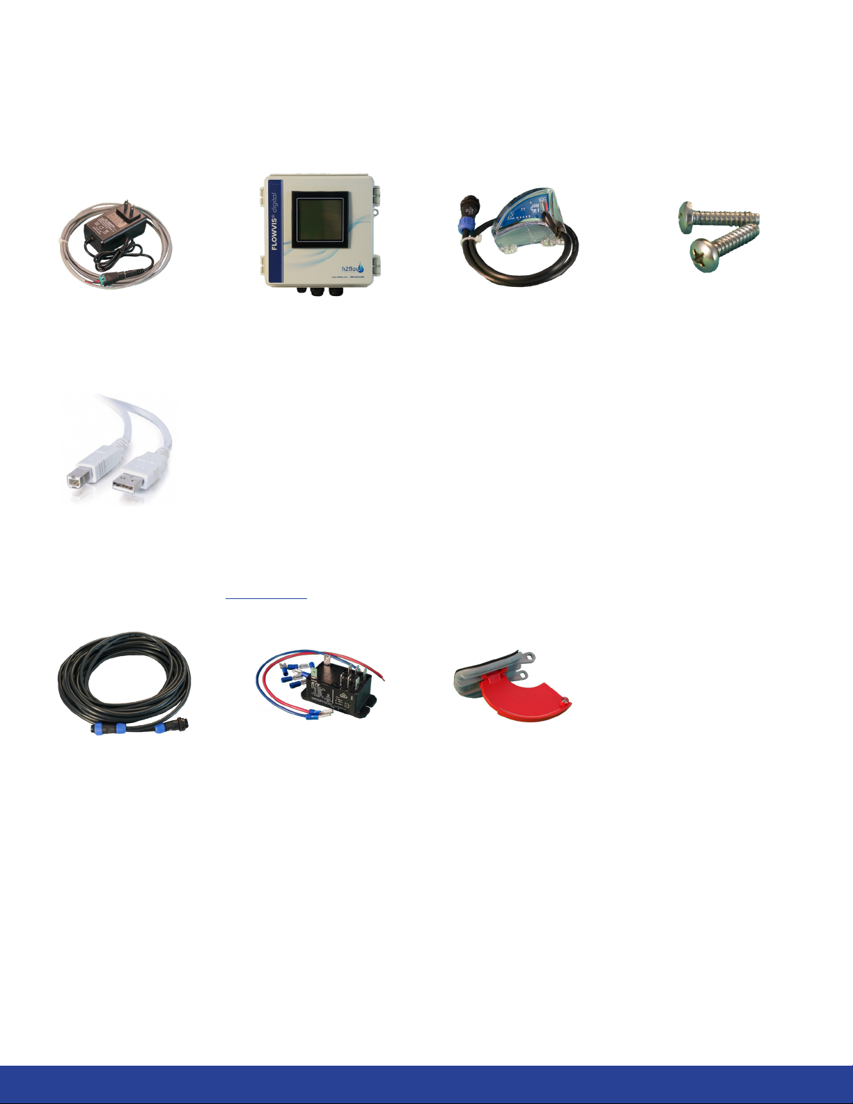
1. Check the contents of your FlowVis Digital box to ensure that they comply with the components shown on page 4
of this document
2. Unless previously done in section 6.2, remove the two FlowVis lid screws that will align with the hole mounting tabs
for the sensor (refer to Fig.2.5 on pg. 7).
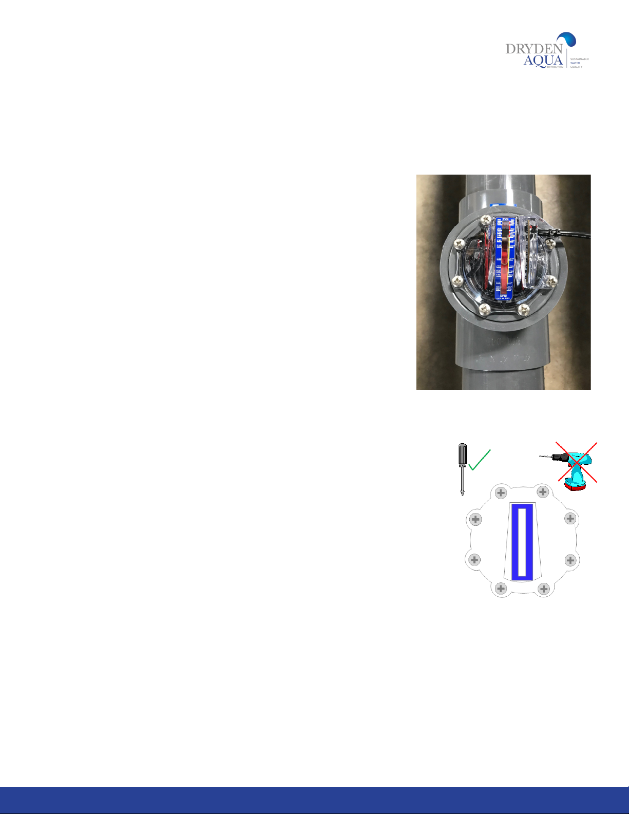
3. Mount the sensor, ensuring that it is fully seated and the screw holes line-up with those on the FlowVis lid assembly (see
Fig.2.5).
4. Place the 2 extended screws provided with your FlowVis Digital (Fig.1.3 on page 4) in the holes for the sensor and
using a hand Phillips-head screwdriver, slowly tighten the screws. Do not fully tighten either screw before proceeding
to the next, i.e., pull them down slowly, multiple times to avoid stressing and cracking the sensor. Screws should be
tighteneed to a nal torque of 25 in./lbs. or 2.8 Nm. Disclaimer: Under no circumstances should the screws in the
FlowVis lid assembly or sensor be tightened with an electric screwdriver in the‘drill’setting. This can result in a
cracked lid or sensor, and will invalidate the product warranty.
5. Mount the FlowVis Digital Display enclosure in a location that is: a) convenient for viewing, b) close enough to the
FlowVis ow meter for the sensor cable length (including any extension cables you may have purchased), and c)
close enough to a 100-240VAC receptacle to allow the power supply to connect. Note: The power supply output
(12VDC) cable has a total length of 10 feet / 3M, but can be extended up to a total length of 24 feet / 8M. It is essential that
its polarity is maintained. Good electrical practices should be used when extending this cable.
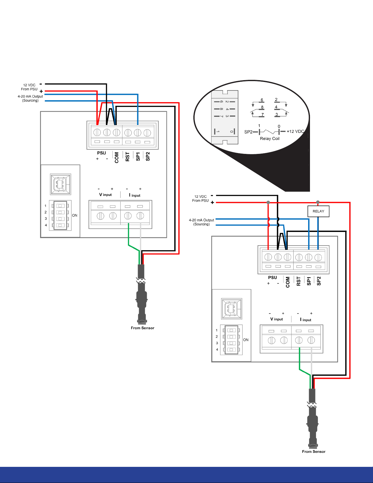
6. f ) Connect the Power Supply low voltage (12VDC) output to the Display (see wiring diagrams on pages 9 & 10).
7. g) Connect the Sensor to the display using either the standard-length cables provided or the extension cable (if
purchased).
8. Disclaimer: The sensor-to-display cables MUST NOT be cut or spliced in any way. Doing so will invalidate the
FlowVis Digital product warranty. If these cables are longer than needed, we suggest coiling the excess cable
and tying with a zip-tie.
9. h) Plug in the Power Supply and ensure that the Digital Display illuminates and the blue light on the sensor is on (not
ashing). If the blue light is ashing, please refer to section 6.4.
10. i) If being used, connect 4-20 mA output to external equipment such as a VFD (see Fig.2.9).
11. j) If being used, connect the alarm relay (see Fig.3.1).
12. k) Proceed to the Programming section.

9
8. Wiring
Power Supply Wiring
Fig 2.7
Fig 2.8
Sensor Wiring
WWW.DRYDENAQUA.COM

10
9. Output
Auxiliary Relay
Wiring
Fig 3.1
4-20 mA Wiring
Fig 2.9
Auxiliary Relay External
Equipment Connection
COIL
Fig 3.0
10

10. Programming
To proceed with programming, rst locate the DIP switches on the back side
of the Digital display. Refer to the circled area in Fig.3.2.
Important Note: It is important to select the correct DIP switch position
based on BOTH the model (rst column) and the pipe size (second column)
shown in the table below as multiple FlowVis models exist for the same pipe
diameter.
11
Fig 3.3 (left) The
default setting for
the DIP switches (all
switches set to the
OFF position).
Fig 3.4 (left) DIP
switch number 1 set
to the ON position.
Fig 3.2
WWW.DRYDENAQUA.COM
Flowvis model / reference # Pipe size DIP - Switch position
1234
d 50mm / ref 90020 DN40 / d50mm / 1.5” OFF ON ON ON
d 63mm / ref 90021 DN50 / d63mm / 2” ON OFF OFF OFF
d 75mm / ref 90026 DN65 / d75mm / 2.5” OFF ON OFF OFF
d 90mm / ref 90022 DN80 / d90mm / 3” OFF OFF ON OFF
d 110mm / ref 90023 DN100 / d110mm / 4” OFF OFF OFF ON
d 160mm / ref 90027 DN150 / d160mm / 6” OFF ON OFF ON
d 200mm / ref 90028 DN200 / d225mm / 8” OFF ON ON OFF

12
11. Operation
After setting the DIP Switches to reect the FlowVis model and Pipe Size employed in your application, the FlowVis Digital
is ready to use. No calibration or further settings are required. However, by default, the FlowVis Digital readout will display
the ow rate in US GPM and the Turnover Rate will show --- (indicating that this function is not activated). If you would like to
change the unit of measurement from US GPM to either LPM or M/hr, and /or activate the pool Turnover Rate function, then it
will be necessary to access these functions as described in the Advanced Setup section.
12. Advanced setup
Although FlowVis Digital will function as a ow meter without additional steps, there are several very useful features that can
be accessed via the‘advanced setup’ procedures. These features comprise:
• Display of the pool turnover rate
• Changing the display’s appearance at a user-dened ow rate
• Programming an (optional) auxiliary relay to operate external equipment such as a Heater or Chemical Feed System,
which will only operate at user dened ow rates
Programming the advanced features will require a Windows-based laptop PC. The initial step is to download the Advanced
Panel Display Software from the internet, we recommend that this be done in an oce environment rather than the pool
equipment room. Note: there is no requirement to connect the laptop to the Display during this initial step.
The laptop PC will require the following:
• Running either a Windows 7, 8, or 10 operating system, using either a 32 or 64-bit conguration
• Microsoft .NET Framework (if you don’t have this, it can be downloaded from www.microsoft.com/net)
• A spare USB 2.0 port (for later connection to the Display)
• An internet connection

13
Advanced setup cont.
Step 2 - Programming the advanced features of the FlowVis Digital Display
With the Congurator program still open, connect the Display to your PC using the Type A to Type B cable that was delivered
with your FlowVis Digital (Fig 1.5).
The FlowVis Digital screen should display the text ‘US.b’, and the Congurator should now look like Fig.3.6, below. Click on
the ‘Congure APM’ button.
Fig 3.6
Step 1 - Download and install the‘Advanced Panel Display’ Congurator Software:
Launch an internet browser page and go to www.h2ow.net/owvis-digital-ow-meter and locate the ‘Congurator’ section,
either by clicking on the tab titled ‘Congurator’ in the page header, or by scrolling down the page to this section.
Click on the ‘Congurator Download’ button. When the Congurator has nished
downloading, open the le, either from your Downloads folder, or from the bar at
the bottom of your browser. Follow the prompts provided by the Setup Wizard and
when asked, click on ‘Save As’. Save the le to your preferred location. The default
le name will be ‘APM Congurator’.
After downloading the le, double-click on the icon labelled ‘APM Congurator’.
You should then see an image on your desktop which resembles Fig 3.5 (right).
Click on the ‘Updates’tab and make sure that the‘Automatic Updates’option is
checked. If ‘Automatic Updates’was un-checked, please check this, and then close
the program and re-launch. If new updates are available, they will be automatically
downloaded and saved to your PC.
The Congurator program has now been successfully installed and your laptop is
ready to connect to the FlowVis Display.
Fig 3.5
WWW.DRYDENAQUA.COM

14
Advanced setup cont.
You can change this value to that desired for your application, and you can also determine the condition that you wish it to
operate, e.g., above or below the programmed value, between or outside the programmed values. Note that when either of
these latter two options are selected, a second value window will appear.
Beneath this you will see an option to select the relay’s sensitivity in detecting the programmed condition at which you wish
it to activate; the default is set to‘low’. It is recommended that you do not adjust this unless you need the relay to operate
immediately when the ow rate hits the programmed level. Please note, however, that the equipment connected to the relay
may experience rapid turning on and o when the ow rate is turbulent and is close to the programmed alarm value.
Finally, you may also wish to change the appearance of the Display when the Alarm condition is met. For example, if you
wanted to make the screen ash red when the ow rate is above a certain value such as a high ow rate, you can achieve
this by checking the ‘Change Backlight’ box and selecting the desired appearance.
When all changes have been made, it is essential that you click on ‘APM’ in the menu at the top of the screen, and then
click on the dropdown option‘Write Conguration to APM’.
Before disconnecting the Type A to Type B cable between your PC and the Display, you may wish to save your conguration
settings. To do so, click on ‘File’ at the top-left of the Congurator screen, and then click on ‘Save Conguration File’ from the
dropdown menu. In the ‘Save As’ dialog box, navigate to the location that you wish to save the le, and give it a Filename
before clicking on the ‘Save’ button.
Fig 3.7
You should now see a screen that looks like the one below (Fig. 3.7):
In this screen, you can program:
• The unit of measurement in either
US GPM (default), LPM, or M3/h
• If being installed to a swimming pool,
then the turnover rate by inserting
the volume of your pool
Please do not change any other values.
‘Alarm 2’has been designated to the
Digital (Open Collector) output that can
be connected to control the optional
Auxiliary Relay kit discussed in section
13 of this manual. In the right-hand side
of this screen, you can program the
condition that you wish the relay to
activate. As can be seen from the default
values, it will operate when the ow rate
is above 25 GPM.

15
13. Auxiliary relay (optional kit)
The Auxiliary Relay option is a valuable feature that allows the FlowVis Digital user to control external devices such as Heater
and Chemical Feeders at user-dened ow rates. For example, you may want to control the Chemical Feeder to operate only
above 20 GPM. Setting this value is discussed in Section 12.
The Auxiliary Relay option kit installs into the rear of the FlowVis Digital Display enclosure and comprises the following items:
Qty. Item
1 Auxiliary Relay with 12 VDC coil and 2 sets of souble pole / double throw dry contacts
1 Set of relay coil wires
1 Cable zip ties (2) with (1) adhesive pad
6 Crimp style Cable Spades
1 Cable Gland
Installation (internal)
1. Secure Relay by removing adhesive backing tape
2. Attach pre-made blue wire to terminal 1 on Relay
3. Attach pre-made red wire to terminal 0 on Relay
4. After removing protective lm, attach Cable Pad to rear of hinged door in location shown
5. Use Zip Ties as shown
6. Connect blue wire to terminal marked ‘SP2’ on rear of Display
7. Connect red wire to terminal marked ‘PSU+’ on rear of Display
8. Drill hole 5/8” (16mm) diameter hole for Cable Gland Be careful not to damage Relay
1
2 3
4 5
6
7
81
1
2
3
4
5
6
7
8
WWW.DRYDENAQUA.COM

16
Auxiliary relay (optional kit) cont.
Installation (external)
The Auxiliary Relay comprises two sets of double pole / double throw dry contacts. Both sets of contacts will operate at
the same programmed ow rate as set in the ‘Advanced Setup’section on page 14. Each of the two sets of contacts has
a normally open and a normally closed relay. The ‘normal state’is the condition that the contacts are in before they are
activated when the coil is energized by the programming value. Please refer to the Auxiliary Relay Connection Diagram (Fig.
3.0) on page 10.
Using the cable spade connectors provided, connect the external wiring to the required Auxiliary Relay outputs. For example,
if the Heater requires a contact closure to operate, connect the heater enabled circuit to either terminals 4 and 2, or 8 and
6. Both of these are normally open contacts that will close when the relay coil is energized by the setting applied in the
‘Advanced Setup’ section on page 14.
14. Display features
The FlowVis Digital Display comprises certain standard features as well as user-dened parameters / adjustments. Standard
features include a Digital and Bar Graph reading of the measured ow rate. The user has the option to program the Unit
of Measurement to be displayed in either US GPM (default), LPM or M3/hour. The patent pending feature that displays the
Turnover Rate is activated by the user during programming. The Display’s format can also be programmed by the user to
change its appearance under prescribed conditions, e.g., ash above or below a certain ow rate. Refer to the ‘Advanced
Setup’ section for more information on how to take advantage of this functionality.
Graphical display
of ow rate
Unit of measurement
options: US GPM,
LPM, m/h
Digital readout of
ow rate
Pool turnover rate
in hours
H2ow Controls
internal reference
only

17
14. Display features cont.
15. Troubleshooting
FlowVis Digital has been designed to be an easy to install, accurate and reliable addition to the renowned FlowVis ow
meter. However, should an unexpected problem occur, please refer to the following Troubleshooting Guide.
As always, please feel free to contact us with any questions or concerns.
Observation Solution
Digital Display not
illuminated
• Check Power Supply is plugged into its receptacle, if yes...
• Check for 12 VDC power at terminals PSU+ and PSU- on rear of Display, if no voltage...
• Check to see if wires from the Power Supply are securely terminated into the PSU+ and
PSU- terminals, if yes...
• Check to see if power source is active. If yes, Power Supply needs to be replaced
Digital Display reads
zero ow rate with pump
running
• Is Display illuminated? If yes...
• Check to see if FlowVis is reading the expected ow. If yes...
• Check to see if there is a steady blue light on the sensor. If no...
• Check sensor wiring and terminations into the rear of the Display - red wire to I input +,
black wire to I input -, and green wire to COM. Is everything is secure and correct? If yes...
continued on next page
On all FlowVis Digital installations for 8-inch FlowVis units, please note that the text ‘X10’ will appear above the ow reading at
all times. See the below examples and instructions on how to properly read these ow rates:
Note the ‘X10’
indicator
Note the
decimal point
92.4 x 10 = 924 GPM 103 x 10 = 1030 GPM
WWW.DRYDENAQUA.COM

18
16. Environmental
See specication section for environmental operating conditions.
For product disposal, follow all local environmental requirements mandated for plastic and electronic equipment.
17. Standards & approvals
Power Supply UL, cUL, CE
Display & Sensor NSF 50 pending
Troubleshooting cont.
Observation Solution
Digital Display not
illuminated (continued
from previous page)
• If the blue light is ashing, the sensor has not detected a magnet in the FlowVis indicator
arm. Contact H2ow for further assistance.
• Is this a retrot to an existing FlowVis? If yes, did you install a new lid assembly that is
‘Digital’ compatible? If no...
• Contact H2ow for further guidance
Digital Display is reading
a ow rate that is
signicantly dierent to
the FlowVis
• Check that the DIP switch settings applied in ‘Programming’section, correcly related to
the FlowVis model being used. If applied correctly, please contact Dryden Aqua for further
guidance.
Turnover rate appears to
be inaccurate
• The turnover rate is calculated by the programmed pool volume, divided by the ow
rate. Perform a manual calculation as follows: (Pool Volume ÷ Flow Rate from FlowVis) ÷
60 = Turnover rate in hours. If this number is different to the value shown on the FlowVis
Display, reconnect your laptop and check that the pool volume has been accurately
entered.
External equipment such
as a Heater or Chemical
Feeder, that is being
controlled by the Auxiliary
Output, is turning on and
o erratically
• Reconnect laptop PC and check that the Sensitivity Level has been set to‘Low’. If yes...
• Check the flow rate reading is well above (or below) the set level programmed to turn
on (or off) the Auxiliary Output. If the actual flow rate is close to the set value and there is
turbulence causing the flow rate to be erratic, consider adjusting the set point value.
Display is showing
the wrong unit of
measurement
• Connect your laptop and check to see the required Unit of Measurement (US GPM, LPM
or M3/hour) has been selected. Change as necessary.

19
18. Specications
Display Enclosure
Enclosure Material...................................................................ABS
Rating ..........................................................................................NEMA 4X / IP66
Dimensions................................................................................6” x 6” x 3.5” / 152mm x 152mm x 90mm (HxWxD)
Mounting Brackets (4) ...........................................................Stainless Steel
Outdoor (UV inhibitor included)........................................Special Order
Display
Display.........................................................................................LCD
Backlight Colors .......................................................................Red, Green, White
Display Cable with Socket....................................................138” (3.5M) long
Sensor
Sensor Housing Material.......................................................Polycarbonate (clear)
Molded Cable with Plug .......................................................20” (0.5M) long
Display to Sensor Extension Cable (optional)
Pre-formed with Attached Plug and Socket..................25 feet (7.62M) long
Power Supply
Power Connection ..................................................................Receptacle style
Power Source ............................................................................100-240VAC, 0.4 Amps
Power Output ...........................................................................12 VDC, 1.0 Amps
Low Voltage Cable Length ...................................................10’ (3M)
Auxiliary Relay
Output Contacts ......................................................................Double Pole, Double throw Form C Dry Contacts
Contact Ratings........................................................................20A max
Relay Coil....................................................................................12VDC (sourced and controlled by the Display)
Analog Output (4-20mA)
Scaled to.....................................................................................4 mA = zero ow, 20 mA = max ow rate limit of installed FlowVis
Output Format..........................................................................Voltage sourced from FlowVis Digital Display
Maximum Load ........................................................................250 ohms
Accuracy
Flow Rate Accuracy.................................................................>97.9% for all FlowVis models
Environmental
Operating Temperature ........................................................32 to 122°F (0 to 50°C)
Storage Temperature .............................................................-4 to 140°F (-20 to 60°C)
WWW.DRYDENAQUA.COM

19. Warranty
Dryden Aqua Distribution AG - Industriering 68 - 4227 Büsserach -Switzerland
Mail: sales@drydenaqua.com - Phone: +41 61 789 91 80
For more information. please visit our website: www.drydenaqua.com
Denition
H2ow Controls, Inc., warrants the FlowVis® product for 3-years from its date of supply from H2ow Controls, Inc. or its
stocking Distributor. In the event that the product experiences a premature failure due to defective workmanship or materials,
H2ow will, at its discretion, replace either the failed component(s) or the complete FlowVis Digital unit. H2ow shall not be
responsible for third-party labor or any consequential losses. Damage caused by improper installation, misuse or exposure to
corrosive chemicals, will not be covered by this warranty.
Eligibility
This warranty extends to the original purchaser only or to the end-user client of an H2ow Controls Inc. authorized aliate.
How to obtain service
To obtain service under the terms of this warranty, the customer is required to notify H2ow Controls Inc. before the expiration
of the warranty period and to return the item in accordance with H2ow Controls Inc’s product return policy. Any product
returned for warranty repair must be accompanied by a full fault report specifying the symptoms and the conditions under
which the fault occurs. Should H2ow Controls Inc. incur additional cost as a result of a failure to complete the appropriate
paperwork, an administrative charge may be levied.
Exclusions
This warranty shall not apply to any defect, failure or damage caused by improper use or improper or inadequate care.
H2ow Controls Inc. shall not be obligated to provide service under this warranty if:
a) damage has been caused by a failure to make a full and proper inspection of the product (as described by the
documentation enclosed with the product at the time of shipment) on initial receipt of the product following shipment;
b) damage has been caused by the attempts of individuals, other than H2ow Controls Inc. sta to repair or service the
product;
c) damage has been caused by the improper use of the product, including but not limited to, the cracking or breakage of
a FlowVis Digital sensor or FlowVis lid due to the over-tightening of lid screws, damage to the FlowVis Digital LCD display
screen due to misuse or excessive exposure to chemicals, the splicing or cutting of cables or wires unless explicitly instructed
to do so during the installation process, or the installation of an indoor-rated FlowVis Digital enclosure in an outdoor
environment.
Charges
Under cover of this warranty, H2ow Controls Inc. will pay the carriage and insurance charges for the
shipment of defective product back to H2ow Controls Inc. and for its return to the client’s original site
of dispatch except when:
a) H2ow Controls Inc’s product return policy has not been followed.
b) product failure is caused by any of the exclusions described at paragraph 4 above, when the customer will be liable for the
full cost of the repair (parts and labor) plus all carriage and insurance costs to and from H2ow Controls Inc’s premises.
c) the product is damaged in transit and a contributory cause is inadequate packaging. It is the customer’s responsibility
to ensure that the packaging used to return equipment to H2ow Controls Inc. is the same, or has equivalent protective
qualities, to that used to ship the product to the customer in the rst instance. Any damage resulting from the use of
inadequate packaging will nullify H2ow Controls Inc’s obligations under this warranty.
Should the customer’s product be damaged in transit following a repair at H2ow Controls Inc’s site, a
full photographic record of the damage must be obtained (packaging and the product) to support any claim for recompense.
Failure to present this evidence may limit H2ow Controls Inc’s obligations under this warranty.
THIS WARRANTY IS GIVEN BY H2FLOW CONTROLS INC. IN LIEU OF ANY OTHER WARRANTIES, EXPRESSED OR
IMPLIED, INCLUDING BUT NOT LIMITED TO ANY IMPLIED WARRANTY OF MERCHANTABILITY, NON INFRINGEMENT
OR FITNESS FOR A PARTICULAR PURPOSE. H2FLOW CONTROLS INC SHALL NOT BE LIABLE FOR ANY SPECIAL,
INDIRECT, INCIDENTAL OR CONSEQUENTIAL DAMAGES OR LOSSES. WE SPECIFICALLY DISCLAIM ANY AND
ALL WARRANTIES TO CUSTOMERS OF THE CUSTOMER. THE CUSTOMER’S SOLE REMEDY FOR ANY BREACH
OF WARRANTY IS THE REPAIR OR REPLACEMENT, AT H2FLOW CONTROLS INC’S DISCRETION, OF THE FAILED
PRODUCT.
IMPORTANT, PLEASE READ AND KEEP THIS DOCUMENT ON RECORD.
WWW.DRYDENAQUA.COM
This manual suits for next models
7
Table of contents
Popular Measuring Instrument manuals by other brands

S+S Regeltechnik
S+S Regeltechnik RHEASREG KLSW Operating Instructions, Mounting & Installation

Anaheim Scientific
Anaheim Scientific H100 instruction manual

ITRON
ITRON RF1 instruction manual

HP
HP 5004A Operating and service manual

Facom
Facom 720.C instruction manual

Fiberstars
Fiberstars WaterLevV IGW 6000 Operation and maintenance manual

BIRD
BIRD Thruline 4304A Operation manual

Haglof
Haglof Vertex Laser Geo user guide

PCE Instruments
PCE Instruments PCE-TG200 instruction manual

geo-FENNEL
geo-FENNEL Geo5X-L360 HP user manual

KROHNE
KROHNE OPTISONIC 6300 F Ex Series quick start

Dwyer Instruments
Dwyer Instruments Rate-Master RMC Installation and operating instructions