manuals.online logo
Brands
  1. Home
  2. •
  3. Brands
  4. •
  5. Arecont Vision
  6. •
  7. Security Camera
  8. •
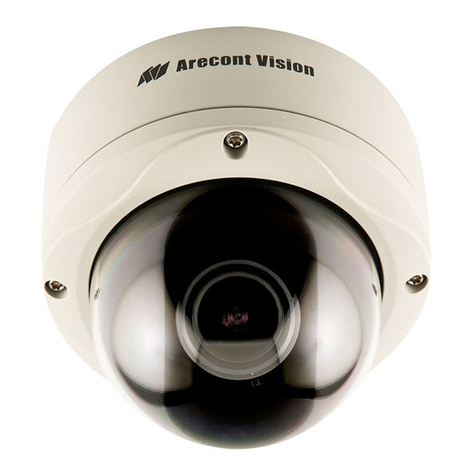
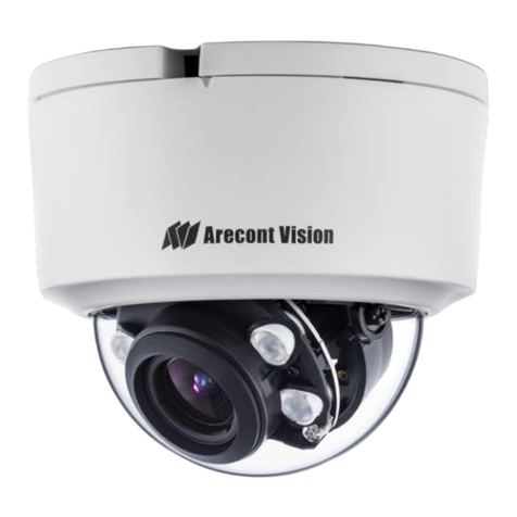
  9. Arecont Vision megadome User manual

Arecont Vision megadome User manual

425 E. Colorado St., 7th Floor
Glendale, CA 91205
Phone: +1.818.937.0700
Fax: +1.818.937.04 4
www.arecontvision.com 1 | P a g e
Arecont Vision
MegaDome
TM
Installation Manual
425 E. Colorado St., 7th Floor
Glendale, CA 91205
Phone: +1.818.937.0700
Fax: +1.818.937.04 4
www.arecontvision.com 2 | P a g e
MegaDome™ Installation Manual
Inside the box:
A. Arecont Vision MegaDome
TM
B. Mounting template
C. Magnetic core
D. Pack of four (4) wood screws and four (4) dry wall anchors
E. One double sided hex key
F. One single sided hex key
G. Security L-key
H. Power cable
Not included but needed:
•#1 Phillips head screw driver
•#2 Phillips head screw driver
Image 1
A
H
G
F
E
D
C
B
425 E. Colorado St., 7th Floor
Glendale, CA 91205
Phone: +1.818.937.0700
Fax: +1.818.937.04 4
www.arecontvision.com 3 | P a g e
Mounting the Camera:
1. Remove camera and hardware from the box.
Image 2 Image 3
2. Using the Mounting template, prepare the mounting surface. NOTE: the 19.5mm
diameter hole on the Mounting template is where the Ethernet cable will be
exiting the MegaDome
TM
align accordingly. If using the side conduit hole please
see step 9 below.
3. Using Security L-key, loosen the four (4) screws securing the dome cover (Image 2).
Remove vandal resistant dome cover. NOTE: The screws will not remove from the
dome cover.
4. Run Ethernet cable through the hole on the bottom of the camera (Image 3) and
plug it into the RJ45 port. NOTE: If the camera will be powered via PoE please skip
to step 6.
5. If the camera is powered by an outside power supply, run the supplied power
cable through the hole and connect it to its respective connector inside the
camera (Image 3). NOTE: Make sure that your installation of wires complies with
Electrical Code of the local government where the camera is installed and no
bare wires are exposed.
RJ-45
POWER
HOLE
425 E. Colorado St., 7th Floor
Glendale, CA 91205
Phone: +1.818.937.0700
Fax: +1.818.937.04 4
www.arecontvision.com 4 | P a g e
. Align the holes in the camera with the prepared holes on the mounting surface.
Attach the camera to the mounting surface with the wood screws.
Image Image 5
7. Install the included magnetic core onto the Ethernet cable as shown in Image .
NOTE: Ensure both tabs are tightly secured.
8. Reference Image 5 for positioning of the magnetic core.
Image 6
425 E. Colorado St., 7th Floor
Glendale, CA 91205
Phone: +1.818.937.0700
Fax: +1.818.937.04 4
www.arecontvision.com 5 | P a g e
9. If you are using the side conduit opening, remove the conduit plug by first
removing the Allen set screw using the appropriate provided Allen key (Image 6).
Adjusting the Tilt, Pan and Focus:
10. To adjust the tilt, use a #1 Phillips screwdriver to loosen the screw on the side of the
plastic lens bracket 1/4 turn (Image 7). CAUTION: Do not remove the screw!
11. Adjust lens tilt as required and tighten the screw from step 10.
Image 7 Image 8
12. To adjust the pan, use a #2 Phillips screwdriver to loosen the screw as shown in
Image 7.
13. Adjust the pan as required and tighten the screw from step 2.
14. To adjust back focus ring (unit comes pre-back focused), loosen the two (2) set
screws with the appropriate Allen key as shown in Image 8 (only one of two screw
holes shown). Adjust the silver back focus ring as needed and tighten down the
set screws.
TILT
BACK
FOCUS
PAN
425 E. Colorado St., 7th Floor
Glendale, CA 91205
Phone: +1.818.937.0700
Fax: +1.818.937.04 4
www.arecontvision.com 6 | P a g e
Image 9
15. To focus the lens, loosen the three set screws as shown in Image 9 and adjust each
as needed. A adjusts the varifocal, B adjusts the iris, C adjusts the focus.
1 . Remove the protective film from the camera dome. NOTE: be cautious to not
scratch the vandal dome cover.
17. Secure the vandal dome cover to the camera.
A
C
B
425 E. Colorado St., 7th Floor
Glendale, CA 91205
Phone: +1.818.937.0700
Fax: +1.818.937.04 4
www.arecontvision.com 7 | P a g e
MegaDome™ Pendant Installation Instructions
Inside the box:
A. Top shield
B. Pendant Mount
C. Mounting template
D. Pack of four (4) machine screws
E. Pack of four (4) wood screws and four (4) dry wall anchors
F. Large round rubber gasket
G. Smaller square rubber gasket
Not included but needed:
•#2 Phillips head screw driver
Image 10
E
C
G
F
D
B
A
425 E. Colorado St., 7th Floor
Glendale, CA 91205
Phone: +1.818.937.0700
Fax: +1.818.937.04 4
www.arecontvision.com 8 | P a g e
18. Remove Pendant Mount and hardware from the box.
Image 11 Image 12
19. Using the Mounting template, prepare the mounting surface.
20. Place small gasket onto pendant dome as shown on Image 11.
21. Attach Dome to Pendant as shown on Image 12 using the four machine screws
provided.
20. Install large round rubber gasket onto Pendant as shown on Image 12. Be sure to
align the holes appropriately.
21. Run Ethernet Cable and outside power cable (if necessary) through the Pendant.
22. Attach Pendant to the ceiling using the four wood screws provided.
25. For installation of the camera, please reference “Mounting the Camera”.
425 E. Colorado St., 7th Floor
Glendale, CA 91205
Phone: +1.818.937.0700
Fax: +1.818.937.04 4
www.arecontvision.com 9 | P a g e
MegaDome™ Wall Mount Installation Instructions
Inside the box:
A. Top shield and Wall mount
B. Mounting template
C. Pack of four (4) machine screws
D. Pack of four (4) wood screws and four (4) dry wall anchors
E. Large round rubber gasket
Not included but needed:
•#2 Phillips head screw driver
Image 13
E
B
D
C
A
425 E. Colorado St., 7th Floor
Glendale, CA 91205
Phone: +1.818.937.0700
Fax: +1.818.937.04 4
www.arecontvision.com 10 | P a g e
2 . Remove Wall Mount and hardware from the box.
Image 1
27. Using the Mounting template, prepare the mounting surface.
28. Install large round rubber gasket onto Pendant as shown on Image 1 . Be sure to
align the holes appropriately. NOTE: the four little rubber nipples protrude into the
top shield.
29. Run Ethernet Cable and outside power cable (if necessary) through the Pendant.
30. Attach Wall Mount to the wall using drywall screws.
31. For installation of the camera, please reference “Mounting the Camera”.
425 E. Colorado St., 7th Floor
Glendale, CA 91205
Phone: +1.818.937.0700
Fax: +1.818.937.04 4
www.arecontvision.com 11 | P a g e
This page intentionally left blank
425 E. Colorado St., 7
support@arecontvision.com
425 E. Colorado St., 7th Floor
Phone:
www.arecontvision.com
Arecont Vision, LLC
425 E. Colorado St., 7
th
Floor
Glendale, CA 91205
[email protected]
www.arecontvision.com
+1 (818) 937-0700
(877) CAMERA.8
425 E. Colorado St., 7th Floor
Glendale, CA 91205
Phone:
+1.818.937.0700
Fax: +1.818.937.04 4
12 | P a g e

Other Arecont Vision Security Camera manuals
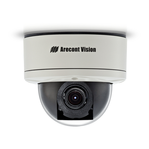
Arecont Vision D4S Series User manual

Arecont Vision

Arecont Vision D4S Series User manual

Arecont Vision AV1215PM-S User manual

Arecont Vision

Arecont Vision AV1215PM-S User manual

Arecont Vision SurroundVideo Omni AV12176DN-NL User manual

Arecont Vision

Arecont Vision SurroundVideo Omni AV12176DN-NL User manual

Arecont Vision MicroDome AV1455DN-F User manual

Arecont Vision

Arecont Vision MicroDome AV1455DN-F User manual

Arecont Vision AV12975DN-NL User manual

Arecont Vision

Arecont Vision AV12975DN-NL User manual

Arecont Vision AV12275DN-NL User manual

Arecont Vision

Arecont Vision AV12275DN-NL User manual

Arecont Vision D4SO Series User manual

Arecont Vision

Arecont Vision D4SO Series User manual

Arecont Vision H.264 Day/Night SurroundVideo Series User manual

Arecont Vision

Arecont Vision H.264 Day/Night SurroundVideo Series User manual

Arecont Vision MegaView 2 AV1225PMIR-S User manual

Arecont Vision

Arecont Vision MegaView 2 AV1225PMIR-S User manual

Arecont Vision AV2100 User manual

Arecont Vision

Arecont Vision AV2100 User manual

Arecont Vision D4SO Series User manual

Arecont Vision

Arecont Vision D4SO Series User manual

Arecont Vision AV08ZMV-300 User manual

Arecont Vision

Arecont Vision AV08ZMV-300 User manual

Arecont Vision MegaDome 2 User manual

Arecont Vision

Arecont Vision MegaDome 2 User manual

Arecont Vision AV1255AM User manual

Arecont Vision

Arecont Vision AV1255AM User manual

Arecont Vision Contera AV02CLB-100 User manual

Arecont Vision

Arecont Vision Contera AV02CLB-100 User manual

Arecont Vision MegaBall AV2245PM-W User manual

Arecont Vision

Arecont Vision MegaBall AV2245PM-W User manual

Arecont Vision Contera Micro Bullet User manual

Arecont Vision

Arecont Vision Contera Micro Bullet User manual

Arecont Vision AV2225PMIR User manual

Arecont Vision

Arecont Vision AV2225PMIR User manual

Arecont Vision SurroundVideo G5 Mini User manual

Arecont Vision

Arecont Vision SurroundVideo G5 Mini User manual

Arecont Vision MegaBall AV2245PM-W User manual

Arecont Vision

Arecont Vision MegaBall AV2245PM-W User manual

Arecont Vision Megaball series User manual

Arecont Vision

Arecont Vision Megaball series User manual

Arecont Vision MegaVideo Flex Series User manual

Arecont Vision

Arecont Vision MegaVideo Flex Series User manual

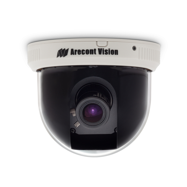
Arecont Vision AV12ZMV-301 User manual
Arecont Vision

Arecont Vision AV12ZMV-301 User manual

Arecont Vision AV2325DNIR User manual

Arecont Vision

Arecont Vision AV2325DNIR User manual
Popular Security Camera manuals by other brands

Huawei IPC6131-WD-A user guide

Huawei

Huawei IPC6131-WD-A user guide

Sony SNC-DH110 installation manual

Sony

Sony SNC-DH110 installation manual

Vivotek IP3111/3121 user manual

Vivotek

Vivotek IP3111/3121 user manual

Novus NVIP-5H-6502M/F user manual

Novus

Novus NVIP-5H-6502M/F user manual

Speco HT-INTB4 user guide

Speco

Speco HT-INTB4 user guide

Fracarro CIR700 Series user manual

Fracarro

Fracarro CIR700 Series user manual

SCS Sentinel Incam SECRET Installation and user manual

SCS Sentinel

SCS Sentinel Incam SECRET Installation and user manual

ELRO C703IP user manual

ELRO

ELRO C703IP user manual

Dometic PerfectView CAM11 installation manual

Dometic

Dometic PerfectView CAM11 installation manual

Samsung SCP-2371 Specifications

Samsung

Samsung SCP-2371 Specifications

JVC TK-C1480B instructions

JVC

JVC TK-C1480B instructions

ALIBI ALI-IPU3130R Quick installation guide

ALIBI

ALIBI ALI-IPU3130R Quick installation guide

Direct IP IDIS DC-D4537RXA installation manual

Direct IP

Direct IP IDIS DC-D4537RXA installation manual

Safety Vision 60-220003 user guide

Safety Vision

Safety Vision 60-220003 user guide

Monacor INC-4000BX instructions

Monacor

Monacor INC-4000BX instructions

FLIR DNV14UX2R instruction manual

FLIR

FLIR DNV14UX2R instruction manual

Bosch REG‑Z1‑8050‑XC‑00E‑01 Specifications

Bosch

Bosch REG‑Z1‑8050‑XC‑00E‑01 Specifications

Sony IPELA SNC-DH120T Specifications

Sony

Sony IPELA SNC-DH120T Specifications

manuals.online logo
manuals.online logoBrands
  • About & Mission
  • Contact us
  • Privacy Policy
  • Terms and Conditions

Copyright 2025 Manuals.Online. All Rights Reserved.