Argo-Hytos UM 045 User manual

Subject to change · UM 045_14264401 · 0916 · EN
Page 1
www.argo-hytos.com
Safety and operating instructions
Read safety and operating instructions before use.
Note: Illustrations do not always correspond exactly to the original. No legal claims come into
being due to information provided in error. Subject to design changes.
© All rights are reserved by ARGO-HYTOS GMBH, even in the event of industrial property rights.
Any right of disposal such as copying and distribution rights shall remain with us.
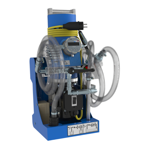
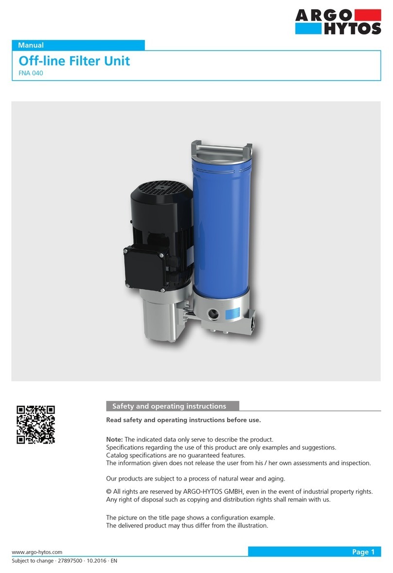
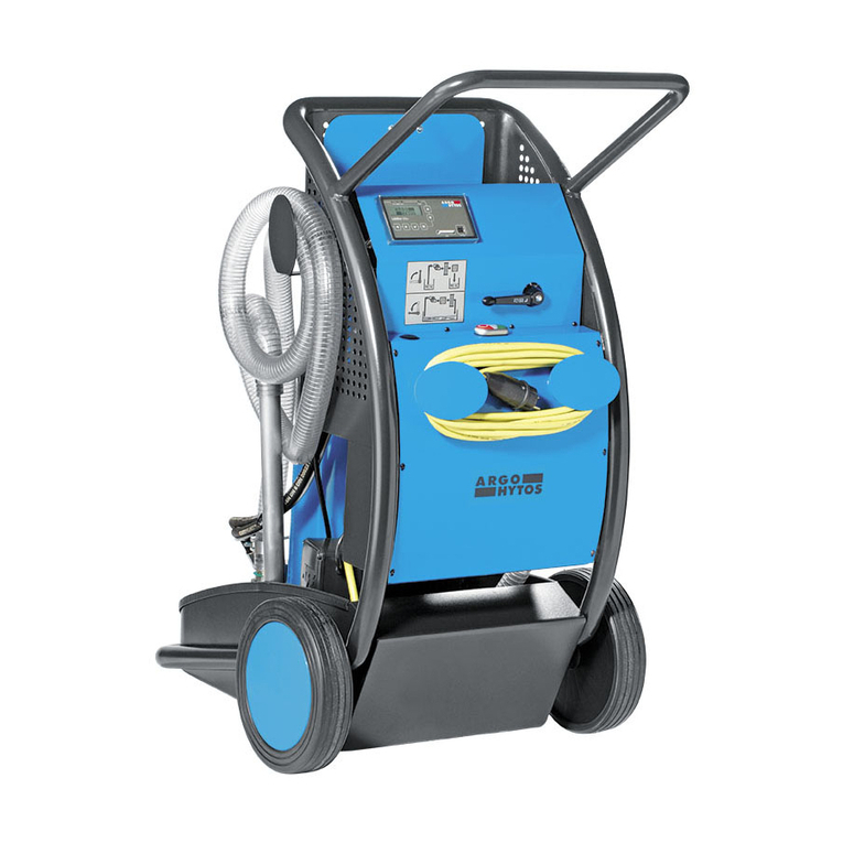
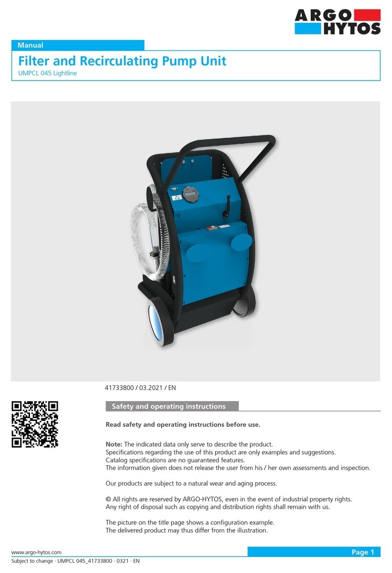
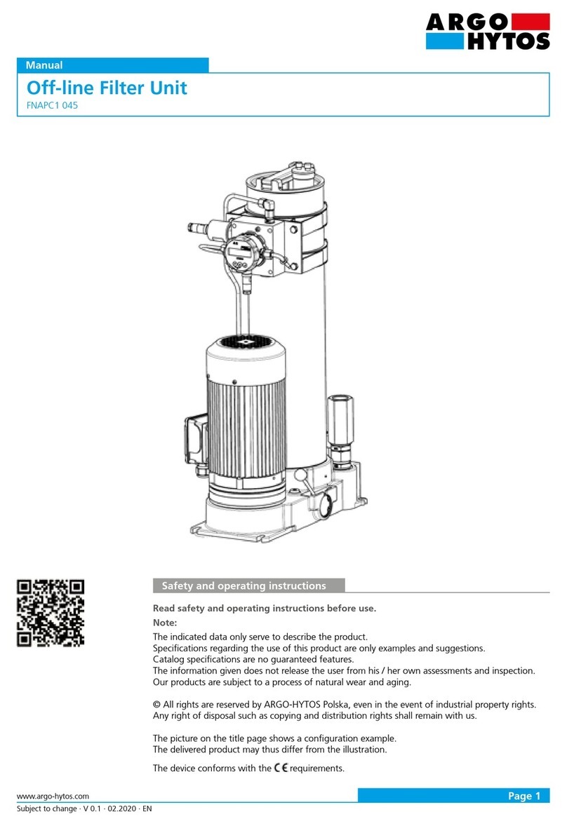
The picture on the title page shows a configuration example.
The delivered product may thus differ from the illustration.
Filter Unit Ecoline
UM 045 / UMP 045
Manual

Subject to change · UM 045_14264401 · 0916 · EN
Page 2 www.argo-hytos.com
Contents
Filter Unit Ecoline UM 045 / UMP 045
Contents ............................................................................................................................................................................. 2
1. Intended purpose ............................................................................................................................................................. 4
1.1 Scope of use........................................................................................................................................................................ 4
1.2 With UMP 045 .................................................................................................................................................................... 4
1.3 Keeping to the permitted operating conditions.................................................................................................................... 4
1.4 Reasonably foreseeable misuse ............................................................................................................................................ 4
2. Safety notes and commissioning .................................................................................................................................... 5
2.1 General references............................................................................................................................................................... 5
2.2 Meaning of operating instruction symbols ........................................................................................................................... 5
2.3 Required staff qualification .................................................................................................................................................. 5
2.4 Contents of delivery UM 045............................................................................................................................................... 5
2.5 Contents of delivery UMP 045 ............................................................................................................................................. 5
2.6 Do not use or store the device ............................................................................................................................................. 6
2.7 Transport............................................................................................................................................................................. 6
2.8 Mains connection ................................................................................................................................................................ 6
2.9 Essential points to note before commissioning the filter unit................................................................................................ 6
2.10 With UMP 045: Installation of the particle counter PODS pro............................................................................................... 7
2.11 On start up check ................................................................................................................................................................ 8
2.12 If there is an unexpected power failure, it is essential to note these points ........................................................................... 8
3. Dimensions of the device................................................................................................................................................. 9
4. How to operate the filter unit....................................................................................................................................... 10
4.1 Filtering hydraulic fluids in the by-pass flow (note safety instructions) ................................................................................ 10
4.2 Filtering of hydraulic fluids while filling machinery and plant.............................................................................................. 11
4.3 Pumping of hydraulic fluids (e. g. waste oil, filter is by passed)........................................................................................... 11
4.4 To achieve the maximum cleaning performance................................................................................................................. 11
5. Technical data ................................................................................................................................................................. 12
5.1 Device data ....................................................................................................................................................................... 12
6. Operating conditions ..................................................................................................................................................... 13
7. Shutdown and disposal ................................................................................................................................................. 14
8. Maintaining the filter unit ............................................................................................................................................. 15
8.1 Maintenance survey........................................................................................................................................................... 15
8.2 Replacing the filter element ............................................................................................................................................... 15
8.3 Checking / changing of the suction strainer (protective strainer for the pump) ................................................................... 16
9. Faultfinding / troubleshooting...................................................................................................................................... 18
10. Appendix......................................................................................................................................................................... 20
10.1 EU- Declaration of Conformity........................................................................................................................................... 20

Subject to change · UM 045_14264401 · 0916 · EN
Page 3
www.argo-hytos.com

Subject to change · UM 045_14264401 · 0916 · EN
Page 4 www.argo-hytos.com
1. Intended purpose
1.1 Scope of use
›To filter hydraulic fluid in the ‘by-pass flow’ on machinery and plant, taking account of the technical data
(see page 12).
›To filter hydraulic fluids while filling machinery and plant, taking account of the technical data
(see page 12).
›To transfer hydraulic fluids (e. g. waste oil, filter element is by passed) taking account of the technical data
(see page 12).
1.2 With UMP 045
›To monitor the oil cleanliness in the “by-pass flow” while filling machinery and plant.
›To switch off when the defined oil cleanliness has been reached.
1.3 Keeping to the permitted operating conditions
The permitted operating conditions must be mandatorily observed (see page 13).
DANGER
›The manufacturer assumes no liability in the event of improper use or if any modifications are made to the device.
1.4 Reasonably foreseeable misuse
The conveying of the following media is prohibited:
›High flammable fluids, such as petrol or thinners (explosion hazard).
›Food
›The device is not suitable for extracting oil sludge and residues.

Subject to change · UM 045_14264401 · 0916 · EN
Page 5
www.argo-hytos.com
Sign Meaning
This symbol stipulates the wearing of safety gloves.
This symbol stipulates the wearing of safety shoes.
This symbol stipulates the wearing of protective goggles.
This symbol stipulates the disconnection of the device from the power supply.
2. Safety notes and commissioning
2.1 General references
›If oil has leaked out for any reason, immediately close off the oil covered area and cover it with an oil-binding medium
(danger of slipping / skidding).
›When using hydraulic or lubricating oils of low conductivity, there is a risk of static charging. Consult the manufacturer in this case.
›With UMP 045: The measuring values of the first 5 minutes should not be considered as the particle counter initializes and the
hydraulic circuit must stabilize (air bubbles, flushing etc.).
2.2 Meaning of operating instruction symbols
Warning sign, signal word Meaning
DANGER This symbol refers to dangers that could be major or even result in death to
individuals.
WARNING This symbol refers to dangers to machines, materials and the environment.
CAUTION This symbol refers to dangers that are slight to individuals.
NOTE This symbol indicates information for better understanding / use of the machine’s functions.
Table1: Meaning of signs
The text next to the symbols has to be read thoroughly. The symbols used in each case do not replace the security advice.
2.3 Required staff qualification
The device may be operated by the following individuals:
›Persons who have read and understood these operating instructions.
›Persons who have been instructed by trained staff.
›Qualified / specialized staff with adequate training.
The device may be repaired or maintained by the following individuals:
›Qualified / specialized staff with adequate training.
›Work on electrical components: Only electrical specialists with adequate training.
2.4 Contents of delivery UM 045
›Filter Unit UM 045
›Operating Instructions
2.5 Contents of delivery UMP 045
›Filter Unit UMP 045
›Operating Instructions
›Optional: Data cable & Software-CD

Subject to change · UM 045_14264401 · 0916 · EN
Page 6 www.argo-hytos.com
›The operating instructions must remain with the filter unit UM 045 / UMP 045 throughout the life time of the
unit and be available at all times, even though the unit may change hands.
WARNING
2.6 Do not use or store the device
›In rain or in a damp or wet environment.
›Near flammable liquids or gasses.
2.7 Transport
›Wear safety shoes and safety gloves
›During transport, fix the suction and pressure hoses in the holders provided on the frame to prevent the loss of residual oil from
hoses.
›If mobile transporting aids are used, make sure that the unit is stable (tilting danger).
›Do not use stairways or higher pitches
›When situating the unit, look out for a secure position (tilting danger).
›Only lift by crane and approved belts or ropes (empty weight of the unit: UM 045 ca.75 kg or UMP 045 ca. 82 kg resp.).
2.8 Mains connection
›The mains voltage must always match the voltage shown on the nameplate (motor).
›The direction of rotation of the motor must match the direction of rotation arrow on the motor housing
(check this point every time you switch on the unit) (only with 3-phase motor).
›The power source must be suitable and correctly protected by fuses (see page 13).
›Line cross-sections must be adequately dimensioned.
›The cable and connection for power supply must be in perfect condition.
2.9 Essential points to note before commissioning the filter unit
›The operating conditions must be strictly observed.
›The operating instructions have to be read thoroughly.
›The unit must be positioned securely enough and must be free of vibrations (stability, tilting danger).
›Cables and hoses must not be placed in areas where operating staff move around (danger of tripping over).
›When using the hoses during unsupervised operation, make sure that they cannot fall out of the tank.
›The suction and delivery pipes must be immersed far enough under the fluid level so that no air can be sucked in
(suction of air can lead to malfunction).
›If no air is drawn in during the start-up procedure, open the filter housing cover and pour in about 0.5 liters of oil.
›The oil must be compatible with the hydraulic fluid from previous filtrations. If not, the filter unit must be cleaned and the filter
element must be changed.
›The cover of the filter housing must be correctly sealed. If necessary, screw in the cover manually as far as the limit stop. A gap
between the cover and the housing may remain visible.
›With UMP 045: The hydraulic fluid must be free from water
(no oil clouding measuring values can be adulterated by free water in the oil).

Subject to change · UM 045_14264401 · 0916 · EN
Page 7
www.argo-hytos.com
2.10 With UMP 045: Installation of the particle counter PODS pro
›Do not operate the particle counter without return hose. The tank of the particle counter holds a return flow
capacity of max. 8 measurements.
›Danger to the environment by spilling oil.
WARNING
›Disassemble the return flow tank and the hose (item 2) as well as the bottle adapter (item 3) from the particle counter (item 1)
(see illustration 1).
Illustration 3: PODS pro - view 3
Pos. 1
Pos. 2
Pos. 3
Pos. 6
Pos. 2
Illustration 1: PODS pro-view 1
›Attach the provided adapter (item 4) to the particle counter (item 1) and connect the return hose (item 5) to the return connection
(item 6) of the particle counter (see illustration 2).
›Connect the provided data cable to the particle counter (see illustration 2).
›Connection 1: Plug for electric power supply
›Connection 2: Plug for data transfer
Pos. 1
Pos.4 Pos. 5
Pos. 6
Pos. 5
Illustration 2: PODS pro-view 2
›Attach the particle counter (item 1) by pressing down to the equipment rack (item 7). The fixing bracket (item 8) catches the article
counter (see illustration 3).
Pos. 1 Pos. 7
Pos. 8
Pos.1
Pos. 8
Pos. 7

Subject to change · UM 045_14264401 · 0916 · EN
Page 8 www.argo-hytos.com
›Connect the suction and return hose (DN 6, black color) to the quick fitting couplings (item 9 and item 10) at the adapter
(item 4) (see illustration 4)
Pos. 4 Pos. 9
Pos. 10
Illustration 4: Adapter with quick fitting couplings
›Connect the connecting cable to the interface (item 11) of the filter unit (see illustration 5).
Pos. 11
Illustration 5: View of Filter Unit UMP 045
2.11 On start up check
›If the filter unit is tight / sealed.
›If the direction of rotation of the motor matches the direction of rotation arrow on the motor housing. If not, only allow specialized
staff to invert the phases (only with 3-phase motor).
›De-aeration of the unit: To ventilate the unit automatically, release the black cap at the ventilating valve (see page 9),
but do not unscrew it.
By means of manual de-aeration (red cap), the ventilating valve can be checked. With activation, oil must escape within a short time.
By this check-up you additionally prevent jamming of the float valve.
2.12 If there is an unexpected power failure, it is essential to note these points
›Switch off the unit or disconnect from the mains supply to prevent the possibility of subsequent damage to the environment and /
or people when the power returns.
→ Possible subsequent damage: - oil may overflow
- danger of slipping on leaked oil

Subject to change · UM 045_14264401 · 0916 · EN
Page 9
www.argo-hytos.com
3. Dimensions of the device
ca. 700
808
1045
933
565
5
17
2
4
16
3
6
19
11
10
12
14 18
8
9
1
564
786
258
13
15
21
20
7
1 Equipment rack 13 Clogging indicator
2 Drip tray 14 Pump block
3 Electric box / electric unit 15 Cover with ventilating valve
4 Wheel / wheel cap 16 Motor-pump unit
5 Hose support 17 Filter pipe / filter element
6 Cable holder 18 Suction strainer
7 On-off switch 19 Filing tray
8 Suction pipe
9 Suction hose With UMP 045
10 Pressure pipe
11 Pressure hose 20 PODS-fixing bracket
12 Rotary valve 21 Tray for PODS

Subject to change · UM 045_14264401 · 0916 · EN
Page 10 www.argo-hytos.com
4. How to operate the filter unit
›The filter unit is equipped with a suction strainer on the suction side, which has to be maintained regularly
(see page 9, item 18).
›A defective or missing suction strainer can lead to pump damage.
WARNING
›Wear safety gloves, safety shoes and protective goggles.
4.1 Filtering hydraulic fluids in the by-pass flow (note safety instructions)
›Connect and fix the filter unit as described under point 2 (with 3 phase motors please observe the rotating direction).
›Immerse the suction pipe and the delivery pipe into the hydraulic tank of the machine or plant.
Note: The distance between intake side and delivery side should be kept apart as far as possible to avoid short-circuit of the oil
flow.
›Switch rotary valve to position II (filtering) (see illustration 6).
›Switch on the filter unit by using the on-off switch.
›Check the oil flow (the suction pipe may not be immersed to a sufficient depth in the oil tank).
Note: When starting filtration, filling of the filter unit may take a few seconds.
›Check the element for clogging, using the clogging indicator.
›At the end of filtration, switch the rotary valve to position I (pumping). Pull the suction pipe out of the hydraulic tank of the
machine or plant and draw in air for max. 30 seconds. Residual oil from the filter unit will be returned via delivery pipe into the
hydraulic tank of the machine or plant.
›Switch off the filter unit by using the on-off switch.
Illustration 6: Switch settings of the rotary valve

Subject to change · UM 045_14264401 · 0916 · EN
Page 11
www.argo-hytos.com
4.2 Filtering of hydraulic fluids while filling machinery and plant
›When refilling, make sure that there is no waste oil left in the machine or plant.
›Connect the filter unit as described under point 2 (with 3 phase motors please observe the rotating direction).
›Immerse the suction pipe into the oil tank (fresh oil).
›Immerse the delivery pipe into the hydraulic tank of the machine or plant.
›Switch rotary valve to position II (filtering).
›Switch on the filter unit by using the on-off switch.
›Check the oil flow (the suction pipe may not be immersed to a sufficient depth in the oil tank).
Note: When starting filtration, filling of the filter unit may take a few seconds.
›Check the element for clogging, using the clogging indicator.
›Monitor the filling level of the machine or plant and once the desired filling quantity has been reached, switch off the filter unit by
using the on-off switch.
4.3 Pumping of hydraulic fluids (e. g. waste oil, filter is by passed)
›Connect the filter unit as described under point 2 (with 3-phase motors observe rotating direction).
›Immerse the suction pipe into the hydraulic tank of the machine or plant.
›Immerse the delivery pipe into an empty container (oil tank).
›Switch the rotary valve to position I (pumping) (see illustration 6).
›Switch on the filter unit by using the on-off switch.
›Check the oil flow (the suction pipe may not be immersed to a sufficient depth in the oil tank).
Note: When starting filtration, filling of the filter unit may take a few seconds.
›Monitor the procedure. As soon as the machine / plant has completely been pumped empty, switch off the unit.
› With UMP 045:
Monitor the cleanliness and switch off the filter unit as soon as the defined oil cleanliness has been reached.
NOTE
›The unit must be completely de-aerated.
›Air bubbles can adulterate the measuring values.
›The specified media temperatures must be adhered to (see page13).
›Incorrect viscosities can adulterate the measure values.
›Connect and fix the filter unit as described under point 2 (with 3 phase motors please observe the rotating direction).
›Immerse the suction pipe and the delivery pipe into the hydraulic tank of the machine or plant.
Note: The distance between intake side and delivery side should be kept apart as far as possible to avoid short-circuit of the oil
flow.
›Switch the rotary valve to position II (filtering), switch off the particle counter.
›Switch on the filter unit by using the on-off switch. Let the unit operate for 3 to 5 minutes to de-aerate the system.
Then switch off the UMP 045 again.
›Program the particle counter to the desired oil cleanliness (see user manual PODS).
› Consider the switching on sequence by all means (disregarding can lead to mal-functioning):
1. Start the counting process by pressing the start-button at the particle counter.
2. Switch on the UMP 045 by using the on-off switch.
3. Make sure that the rotary valve is turned to position II (filtering).
4. Control on the display of the particle counter (counting begins after ca. 3 – 5 sec.).
›The filter unit UMP 045 automatically turns off once the pre-set cleanliness class has been reached.
4.4 To achieve the maximum cleaning performance
›The hydraulic or lubricating system should be operated (recirculation of fluid, low viscosity).
›The distance between intake side and delivery side should be kept apart as far as possible to avoid short-circuit of the oil flow.
›Adhere to the appropriate filtration time (recommended level: 20 minutes per 100 l tank volume).

Subject to change · UM 045_14264401 · 0916 · EN
Page 12 www.argo-hytos.com
5. Technical data
5.1 Device data
Nominal flow rate 45 l/min (50 Hz) or 54 l/min (60 Hz) resp.
Pressure limiting valve 6 ±0,5 bar
Max. operating pressure 7 bar
Filter element
optional
optional
optional
V7.1560-103
V7.1560-06
V7.1560-03
Y7.1560-05
β3(c) ≥ 200
β12(c) ≥ 200
β5(c) ≥ 200
β8(c) ≥ 200 (water absorption capacity ca. 1,5 liters)
NOTE
›With use of water absorbing elements, particle counting is not possible.
›Water in oil can adulterate the measuring results.
Clogging indicator
(all types)
optical clogging indication DG 042-04
∆p = 3,5 ±0,5 bar
Suction side G 1 ¼“ connection with hose DN 32 and suction pipe
(when replacing the suction hose, only use a spiral hose)
Pressure side G 1“ connection with suction hose DN 25 and pressure pipe
Suction strainer screen element 280 µm
Electrical drive for type
UM(P) 045-1153
UM(P) 045-1553
UM(P) 045-1656
1~ AC-motor with operating capacitor
230 V / 50 Hz; 1,1 kW; n= 1500 min
BG 90
UM(P) 045-4153
UM(P) 045-4553
UM(P) 045-4656
3~ three-phase-motor
400 / 460 V - 50 / 60 Hz; 1,1 kW; n = 1500 / 1800 min -1
BG 90
Weight when empty UM 45 ca. 75 kg / UMP 045 ca. 82 kg
Noise intensity level max. 73 dB(A) under operating cond. allowed for cont. operation
max. 78 dB(A) under operating cond. allowed for short-term op
Dimensions 786 x 564 x 1045 (l x b x h)

Subject to change · UM 045_14264401 · 0916 · EN
Page 13
www.argo-hytos.com
6. Operating conditions
Permitted temperature range
for pressurized fluid 0 °C bis 65 °C
ambient 0 °C bis 50 °C
›Contact temperatures according to DIN EN 563 (3) and DIN EN 13202 (4) at the filter unit may be exceeded.
›Burning hazard
Viscosity Viscosities are always dependent on the fluid temperature
Electrical drive Continuous operation min. Continuous operation max. Short-term operation max.
1 ~ 230 V 15 mm2/s 600 mm2/s 800 mm2/s
3 ~ 400 V 15 mm2/s 600 mm2/s 800 mm2/s
Permitted suction heights max. 2,0 m unfilled
max. 6 m in operating condition
Resistance to media Environment-friendly, mineral-oil-based fluids.
Please consult the manufacturer if synthetic fluids are used.
Mains connection
UM(P) 045-1153
UM(P) 045-1553
UM(P) 045-1656
UM(P) 045-8553
UM(P) 045-4153
UM(P) 045-4553
UM(P) 045-4656
230 V - 50 / 60 Hz
16 Ampere
400 / 460 V - 50 / 60 Hz
16 Ampere
Position vertical
DANGER

Subject to change · UM 045_14264401 · 0916 · EN
Page 14 www.argo-hytos.com
7. Shutdown and disposal
›Disconnect the unit from the mains supply before starting any disassembly work.
Disassembly work on electrical components has to be carried out strictly by qualified
electricians.
›Danger of electrical shock
›Disassembly work on the filter unit has to be carried out exclusively by qualified specialists.
›Danger of injuries of any kind.
The final shutdown and disposal requires complex disassembly of the complete power supply, mechanical components and the
disposal of the hydraulic media which remain in the device.
With disassembly and disposal all safety and environmental aspects have to be adhered to.
DANGER

Subject to change · UM 045_14264401 · 0916 · EN
Page 15
www.argo-hytos.com
8. Maintaining the filter unit
›Disconnect the mains plug during maintenance work.
›Danger of electric shock.
DANGER
›Wear safety gloves, safety shoes and protective goggles.
Apart from the filter element (see page 9, item 17) , the suction strainer (see page 9, item 18) and the protection strainer of the
particle counter, the filter unit requires no maintenance.
8.1 Maintenance survey
Maintenance work Order-no. Maintenance intervals
Checking / replacing the
filter element
V7.1560-103 (3 µm)
V7.1560-03 (5 µm)
V7.1560-06 (12 µm)
›As soon as the clogging indicator turns into the red area within
the permitted viscosity range.
Checking / replacing the
suction strainer
S9.0417-13 ›quarterly or
›with corresponding peculiarities (lower volume rate with clean
filter element, too loud operating noise)
8.2 Replacing the filter element
When changing the filter element please proceed as follows (also see illustration 7 and 8):
Before changing the filter element
›Switch the rotary valve to position I (pumping), Pull the suction pipe out of the hydraulic tank of themachine or plant and draw in
air for max. 30 seconds. Residual oil from the filter unit will be returned via the delivery pipe into the hydraulic tank of the machine
or plant.
›Switch off the device and disconnect from the mains supply.
›Let the device cool down if necessary.
Disassembly of the filter element
›Unscrew the housing cover
›Carefully pull the filter element together with the cover out of the housing
(filter element is attached to the cover, allow escaping oil to drip down into the housing).
›Detach the filter element from the cover by moving it as shown in illustration 7.
›Dispose of the filter element in line with environmental requirements, waste code: OILFILTER 16 01 07
Illustration 7: Releasing the fixture at the cover / filter element

Subject to change · UM 045_14264401 · 0916 · EN
Page 16 www.argo-hytos.com
Installing the filter element
›Always replace the O-ring on the cover when changing the filter element (part of scope of delivery).
›Check the type number of the filter element: Compare the numbers of the laser inscription on the filter element, the nameplate or
in the operating instructions (see page 12).
›Attach the filter element to the cover (as shown in illustration 8).
›Carefully insert the cover with the filter element into the filter housing.
›Screw in the cover manually as far as the limit stop (a gap between cover and housing may remain visible.
›Check that the ventilation slits of the electrical motor are not clogged with dirt. Remove deposits, if necessary.
›Restart the device.
›Check the tightness of the filter housing after starting operation.
Illustration 8: Attaching the cover to the element
NOTE
›Oil which accidently spilt onto the filter unit when changing the filter element may seem to be leaked oil.
8.3 Checking / changing of the suction strainer (protective strainer for the pump)
When changing the suction strainer please proceed as follows (also see illustration 7 and illustration 8):
Replacing the suction strainer
›Provide a drip tray for residual oil and the clogged filter element.
›Unscrew the locking screw (item 1) by hexagon socket screw key SW 22.
›Slightly pull the clogged element out of the housing.
›Dispose of the filter element in line with environmental requirements, waste code: OILFILTER 16 01 07
1
Illustration 9: Unscrewing the locking screw

Subject to change · UM 045_14264401 · 0916 · EN
Page 17
www.argo-hytos.com
Installing the suction strainer
›Always replace the O-ring when changing the filter element.
›Attach the suction filter element (item 1) carefully into the pump block.
›Screw in the locking screw and tighten it by hexagon socket screw key SW 22 (MA 25 ±2,5 Nm).
›Check the tightness of the locking screw after starting operation and tighten it if necessary.
1
Illustration 10: Installing the suction strainer
NOTE
›Oil which accidently spilt onto the filter unit when changing the filter element may seem to be
leaked oil.

Subject to change · UM 045_14264401 · 0916 · EN
Page 18 www.argo-hytos.com
9. Faultfinding / troubleshooting
Problem / fault Possible cause Remedy
Electric motor will not turn
on start up
›Electrical cable or plug is faulty Have the cable replaced by a specialist
›No mains voltage Provide mains voltage, e.g.
›Motor is faulty Replace / repair the motor
(repair at manufacturer’s premises)
›Pump is faulty Replace/ repair the pump
(repair at manufacturer’s premises)
›Viscosity is too high (medium) Heat the medium
Electrical motor switches off during
operation
›Electric motor has overheated Let the motor cool down, clean the
ventilation slits if they are clogged
›Pump is blocked Replace / repair the pump
(repair at manufacturer’s premises)
Volume flow rate is clearly too low ›Filter element is clogged Replace the filter element
›Suction strainer is clogged Replace the suction strainer
›Viscosity is too high Heat the medium
›Suction height is too great Adjust the suction height
›Leak on suction side Replace the suction hose or seal the
connection points (tighten them)
›Pump is worn Replace the pump
(repair at manufacturer’s premises)
Operating noise is too loud ›Filter element is clogged Replace the filter element
›Suction strainer is clogged Replace the suction strainer
›Viscosity is too high Heat the medium
›Suction height is too great Adjust the suction height
›Leak on suction side Replace the suction hose or seal the
connection points (tighten them)
›Filter unit is standing on vibration-
sensitive surface (e.g. metal sheet)
Improve conditions of location
Pump does not draw in fluid ›Leak on suction side Replace the suction hose or seal the
connection points (tighten them)
›Sealing plug of the suction
strainer is leaky
Check the sealing ring and replace it if
necessary, check tightening torque
›Unit is running dry
(with new filling)
Prime unit (with 0,5l to 3l)
Particle counter (PODS) does not
start the pre-set program
›Inlet pressure at the PODS is
too low or missing
Pressure or return hose at the
plug-in adapter is loose.
›The switching on sequence has
not been considered
Consider the switching on sequence
›Wiring between PODS und
UMP 045 is faulty, no data transfer
Set up the electrical connection
UMP 045 does not switch off once
the pre-set cleanliness class has
been reached.
›Wrong mode has been adjusted
when programming the particle
counter. No output signal at the
UMP 045
Switch over to the filtering mode when
programming the particle counter.
Consider the operating instructions of
the particle counter.
›Wiring between PODS und
UMP 045 is faulty, no data transfer
Set up the electrical connection

Subject to change · UM 045_14264401 · 0916 · EN
Page 19
www.argo-hytos.com
›Only allow specialized staff to carry out electrical repair work.
›Danger of electric shock
DANGER
›Maintenance work has to be carried out with special care. All parts that come into contact with
the hydraulic medium must be kept free of dirt.
›If dirt enters the pump during maintenance work, optimal function of the filter unit is no longer guaranteed.
In this case the manufacturer assumes no liability.
WARNING

Subject to change · UM 045_14264401 · 0916 · EN
Page 20 www.argo-hytos.com
10. EU - Declaration of Conformity
Änderungen vorbehalten · 14264401 · 08.2016 · DE
Seite 20 www.argo-hytos.com
10. EG-Konformitätserklärung
EU - Konformitätserklärung
EU - Declaration of Conformity
ARGO-HYTOS Polska sp. z o.o.
Władysława Grabskiego 27
32-640 Zator
Tel.: +48 33 873 16 52
Fax: +48 33 873 19 15
www.argo-hytos.com
Die EU - Konformitätserklärung gilt für folgendes
Gerät:
Filteraggregat
The EU - Declaration of Conformity applies
to the following unit:
Filter Unit
UMP 045 / UM 045
Wir bestätigen die Übereinstimmung mit den
wesentlichen Anforderungen der europäischen
Richtlinie(n):
Maschinenrichtlinie 2006-42-EG
EMV Richtlinie 2004/108/EG
We confirm the conformity according to the
essential requirements of the European
directive(s):
Machinery Directive 2006/42/EC
EMC Directive 2004/108/EC
Folgende Norm(en) wurde(n) angewandt: The following standard(s) was (were) applied:
DIN EN 809
DIN EN 60204-1 (VDE 0113-1: 2007-06
Zator, 22.11.2016
(Ort und Datum der
Ausstellung)
(Place and date of issue)
(Unterschrift ) Arkadiusz Noworyta/
Vorsitzender des Vorstandes
(Signature) Arkadiusz Noworyta/
President of the Board
This manual suits for next models
1
Table of contents
Other Argo-Hytos Water Filtration System manuals

Argo-Hytos
Argo-Hytos CFP 03 User manual

Argo-Hytos
Argo-Hytos FNAPC1 045 User manual

Argo-Hytos
Argo-Hytos FAPC 016 User manual

Argo-Hytos
Argo-Hytos FA 016 Maintenance and service guide

Argo-Hytos
Argo-Hytos FA 008 User manual

Argo-Hytos
Argo-Hytos Ecoline UMPC 045 User manual

Argo-Hytos
Argo-Hytos FNA1HV User manual

Argo-Hytos
Argo-Hytos FNS 040 User manual

Argo-Hytos
Argo-Hytos FNA 045 User manual

Argo-Hytos
Argo-Hytos FNA 040 User manual