Argo AEI1G140 3PH User manual

EG
I
F
D
E
P
INSTALLATION INSTRUCTIONS •
ISTRUZIONI D’INSTALLAZIONE
NOTICE D’INSTALLATION •
INSTALLATIONSANLEITUNGEN
INSTRUCCIONES DE INSTALACION •
INSTRUÇÕES DE INSTALAÇÃO
OODDHHGGIIEESSTTOOPPOOQQEETTHHSSHHSS
37.4255.148.02 01/2019
Split air conditioner system •
Condizionatore d’aria split system
Climatiseurs split •
Split-klimagerät
Acondicionador de aire de consola partida sistema split •
Aparelho de ar condicionado-Sistema Split
ΔΙΑΙΡΟΥΜΕΝΕΣ ΜΟΝΑΔΕΣ ΚΛΙΜΑΣΜΟΥ
GR
AEI1G140EMX3PH

2
IMPORTANT!
Please read before installation
This air conditioning system meets strict safety and operating
standards.
For the installer or service person, it is important to install
or service the system so that it operates safely and efficiently.
For safe installation and trouble-free operation, you
must:
• Carefully read this instruction booklet before beginning.
• Follow each installation or repair step exactly as shown.
• Observe all local, state and national electrical codes.
• Pay close attention to all warning and caution notices
given in this manual.
•The unit must be supplied with a dedicated electrical line.
This symbol refers to a hazard or unsafe practice which
can result in severe personal injury or death.
This symbol refers to a hazard or unsafe practice which
can result in personal injury or product or property damage.
If necessary, get help
These instructions are all you need for most installation
sites and maintenance conditions.
If you require help for a special problem, contact our
sale/service outlet or your certified dealer for additional
instructions.
In case of improper installation
The manufacturer shall in no way be responsible for improper
installation or maintenance service, including failure to follow
the instructions in this document.
SPECIAL PRECAUTIONS
• During installation, connect before the refrigerant system
and then the wiring one; proceed in the reverse orden
when removing the units.
When wiring
ELECTRICAL SHOCK CAN CAUSE SEVERE
PERSONAL INJURY OR DEATH. ONLY A
QUALIFIED, EXPERIENCED ELECTRICIANS
SHOULD ATTEMPT TO WIRE THIS SYSTEM.
• Do not supply power to the unit until all wiring and tubing
are completed or reconnected and checked, to ensure
the grounding.
• Highly dangerous electrical voltages are used in this
system. Carefully refer to the wiring diagram and these
instructions when wiring.
Improper connections and inadequate grounding can cause
accidental injury and death.
•Ground the unit following local electrical codes.
• The Yellow/Green wire cannot be used for any connection
different from the ground connection.
• Connect all wiring tightly. Loose wiring may cause
overheating at connection points and a possible fire
hazard.
• Do not allow wiring to touch the refrigerant tubing,
compressor, or any moving parts of the fan.
• Do not use multi-core cable when wiring the power supply
and control lines. Use separate cables for each type of line.
When transporting
Be careful when picking up and moving the indoor and
outdoor units. Get a partner to help, and bend your knees
when lifting to reduce strain on your back. Sharp edges or
thin aluminium fins on the air conditioner can cut your fingers.
When installing...
... In a ceiling or wall
Make sure the ceiling/wall is strong enough to hold the unit-
weight. It may be necessary to build a strong wooden or
metal frame to provide added support.
... In a room
Properly insulate any tubing run inside a room to prevent
"sweating", which can cause dripping and water damage to
walls and floors.
... In moist or uneven locations
Use a raised concrete base to provide a solid level
foundation for the outdoor unit.
This prevents damage and abnormal vibrations.
... In area with strong winds
Securely anchor the outdoor unit down with bolts and a
metal frame. Provide a suitable air baffle.
... In a snowy area (for heat pump-type systems)
Install the outdoor unit on a raised platform that is higher than
drifting snow. Provide snow vents.
When connecting refrigerant tubing
• Observe the information on the tubing length.
• Use the flare method for connecting tubing.
• Apply refrigerant lubricant to the matching surfaces of
the flare and union tubes before connecting them; screw
by hand and then tighten the nut with a torque wrench
for a leak-free connection.
• Check carefully for leaks before starting the test run.
NOTE:
Depending on the system type, liquid and gas lines may
be either narrow or wide. Therefore, to avoid confusion, the
refrigerant tubing for your particular model is specified as
narrow tube for liquid, wide tube for gas.
When servicing
• Turn the power OFF at the main power board before
opening the unit to check or repair electrical parts and
wiring.
• Keep your fingers and clothing away from any moving
parts.
• Clean up the site after the work, remembering to check
that no metal scraps or bits of wiring have been left inside
the unit being serviced.
• Ventilate the room during the installation or testing the
refrigeration system; make sure that, after the installation,
no gas leaks are present, because this could produce
toxic gas and dangerous if in contact with flames or heat-
sources.
WARNING
CAUTION
WARNING
EG

3
Installation site selection
AVOID
• Heat sources, exhaust fans.
• Direct sunlight.
• Damp, humid or uneven locations.
• To make holes in areas where electrical wiring or conduits
are located.
DO
• Choose places as cool as possible and well ventilated.
• use lug bolts or equal to bolt down the unit, reducing
vibration and noise.
Provide a solid base for outdoor unit raised from the ground
level. Fix unit to base using 4 anchor bolts.
10 cm
10 cm
45 cm
SYSTEM WIRING DIAGRAM
EG
1 INDOOR UNIT
POWER SUPPLY
AC 380-415V
3PHASE 50Hz

4
EG
2 INDOOR UNITS
3 INDOOR UNITS
POWER SUPPLY
AC 380-415V
3PHASE 50Hz
POWER SUPPLY
AC 380-415V
3PHASE 50Hz

5
EG
4 INDOOR UNITS
5 INDOOR UNITS
DELAYED FUSE
Main switch for disconnection from the supply line must have a contact separation
in all poles that provides full disconnection under category III overvoltage conditions.
POWER SUPPLY
AC 380-415V
3PHASE 50Hz
POWER SUPPLY
AC 380-415V
3PHASE 50Hz
ELECTRICAL SWITCH (SAFETY)

6
LENGTH, SIZE WIRES AND DELAYED FUSE
ADDITIONAL MATERIAL REQUIRED FOR INSTALLATION (NOT SUPPLIED)
●Deoxidized annealed copper tube for refrigerant tubing connecting the units of the system; it has to be insulated with
foamed polyethylene (min. thickness 8mm).
●
PVC pipe for condensate drain pipe (ø int.18mm) in length suitable to let the condensate flow into the outside drainage.
●
Anti-freeze oil for flare connections (about 30g.).
●
Electric wire: use insulated copper wires of size and length as shown at paragraph “SYSTEM WIRING DIAGRAMS”.
Supply power wire A:
Multipolar electric wire. Size and length of the suggested electric wire are showed on table “electrical data”. The wire
must be Mod. H07RN-F (according to CEI 20-19 CENELEC HD 22). Make sure the length of the conductors between
the fixing point and the terminals allows the straining of the conductors L, N before that of the grounding.
Connecting wire B (SHIELDED):
Bipolar electric shielded wire; size and length of the suggested electric wire are showed on table “electrical data”.
The wires have not to be lighter than Mod. H05VVC4V5-K (according to CEI 20-20 CENELEC HD21).
Connecting wire C (with ground conductor):
Multipolar electric wire; size and length of the suggested electric wire are showed on table “electrical data”. The
wires have not to be lighter than Mod. H07RN-F (according to CEI 20-19 CENELEC HD22).
NARROW TUBE LARGE TUBE
INDOOR UNIT SIZE OUTER DIAMETER MIN. THICKNESS OUTER DIAMETER MIN. THICKNESS
A6,35 mm 0,8 mm 9,52 mm 0,8 mm
B - C - D 6,35 mm 0,8 mm 12,7 mm 0,8 mm
B - C - D (HK) 9,52 mm 0,8 mm 15,88 mm 1 mm
D (ASI) 9,52 mm 0,8 mm 15,88 mm 1 mm
EMIX - EMIX TANK 12,7 mm 0,8 mm 12,7 mm 0,8 mm
쐽Cooling Maximum conditions
Outdoor temperature : 43°C D.B.
Room temperature : 32°C D.B. / 23°C W.B.
쐽Cooling Minimum conditions
Outdoor temperature : –15°C D.B.
Room temperature : 10°C D.B. / 6°C W.B.
쐽Heating Maximum conditions
Outdoor temperature : 24°C D.B. / 18°C W.B.
Room temperature : 27°C D.B.
쐽Heating Minimum conditions
Outdoor temperature : –15°C D.B.
Room temperature : 5°C D.B.
OPERATING LIMITS
MODEL
mm2
MONO SPLIT
AEI1G140 DUAL SPLIT 12,5 A
TRIAL SPLIT
QUADRI SPLIT
PENTA SPLIT
20
30
30
20
30
30
20
30
30
20
50
50
20
30
30
L ("A") m
L ("B") m
L ("C") m
4
0,75
1,5
EG

7
EG
TUBING LENGTH AND ELEVATION DIFFERENCE LIMITS
No additional charge of compressor oil is necessary.
L Tot. = Total tubing length (L1 + L2 + L3...)
Ln = Maximum tubing length of a single indoor unit (n=1,2,3...)
L = Keep Emix tubing as short as possible (MAX. 10/12m)
REQUIRED AMOUNT OF ADDITIONAL REFRIGERANT
For tubing 1/4 “ - 3/8” = 15g/m
For tubing 1/4 “ - 1/2” = 20g/m
For tubing Emix (1/2”) = 20g/m
LIMIT OF ELEVATION DIFFERENCE - OUTDOOR UNIT/INDOOR UNIT: 10m (H1, H2, H3, H4, H5, H6)
LIMIT OF ELEVATION DIFFERENCE BETWEEN INDOOR UNITS: 5m (H)
1.Standard screwdriver
2.Phillips head screwdriver
3.Knife or wire stripper
4.Tape measure
5.Level
6.Sabre saw or key hole saw
7.Hacksaw
8. Core bits ø 5
19.Hammer
10.Drill
11.Tube cutter
12.Tube flaring tool
13.Torque wrench
14.Adjustable wrench
15.Reamer (for
reburring)
16.Hex. key
Tools required for installation (not supplied)
1. REDUCTION 1/2F - 3/8M + PIPE UNION 3/8 (2pcs)
2. REDUCTION 3/8F - 1/2M + PIPE UNION 1/2 (2pcs)
3. COVER (11pcs)
4. DRAIN TUBE
5. ADHESIVE DAMPER (4pcs)
6. TUBES 1/4 - 3/8 + 1/2 - 5/8 for HK (1set)
ACCESSORIES SUPPLIED WITH THE UNIT
2
4
13
MINIMUM LENGTH
L Tot. (m) L n (m) L Tot. (m) L n (m) L (m)
MONO SPLIT 40 - 50 - 5
DUAL SPLIT 40 30 100 30 5
AEI1G140 TRIAL SPLIT 40 30 100 30 5
QUADRI SPLIT 40 30 100 30 5
PENTA SPLIT 40 30 100 30 5
AT SHIPMENT
ADDITIONAL REFRIGERANT
56
REGULATION (EU) No. 517/2014 - F-GAS
The unit contains R410A, a fluorinated greenhouse gas with
a global warming potential (GWP) of 2087.50. Do not
release R410A into the atmosphere.
R410A: 4.40 kg / 9.19 Tonn.CO2

8
EG
Power Supply: 380 - 415 3N ~ 50 Hz
Outdoor - Indoor unit combination table - SYSTEM CONFIGURATION
System Outdoor Combination Emix
type unit n. abcdeEmix tank
1x
1b D (A2W) x
Indoor unit port
D (A2W)
mono
G140
A2W
Outdoor - Indoor unit combination table - SYSTEM CONFIGURATION
System Outdoor Combination Emix
type unit n. abcdeEmix tank
2BA x
2b D (A2W) B A x
3AAAx
3b D (A2W) A A A x
4AAAx
4b C (A2W) A A A x
5BAAx
5b C (A2W) B A A x
penta G140 6C (A2W) BAAAx
7C (A2W) AAAAx
trial
G140
quadri
G140
C (A2W)
D (A2W)
Indoor unit port
C (A2W)
D (A2W)
A2A
A2W
Outdoor - Indoor unit combination table - SYSTEM CONFIGURATION
System Outdoor Combination Emix
type unit n. abcd eEmix tank
8Ax
9B
10 CC
11 CAAx
12 AA
13 C AAA
14 B AAAx
15 A AAAx
16 BAAAA
17 AAAAAx
Indoor unit port
dual
G140
D
trial
G140
D
D
quadri
G140
penta
G140
A2A
A- B- C - D = A2A indoor unit size (see catalogue)
C (A2W) - D (A2W) = A2W indoor unit size (see catalogue)
A2A = air to air models
A2W = air to water models
x=combination with Emix/ Emix tank is possible

9
(go on page 10)
DECLARATION OF CONFORMITY
This product is marked as it satisfies Directives:
–Low voltage no. 2006/95/EC
(Standard: EN60335-2-40:2003 (incl. Corr.:2006) + A11:2004 + A12:2005 +A13:2012 +
A1:2006 + A2:2009 con EN 60335-1:2002 + A11:2004 + A1:2004 + A12:2006 + A2:2006 + A13:2008 + A14:2010 +
A15:2011).
–Electromagnetic compatibility no. 2004/108/EC, 92/31 EEC and 93/68 EEC.
(Standard: EN55014-1 (2006) +A1(2009)
+ A2(2011), EN 55014-2 (1997) + A1(2001) + A2 (2008), EN 61000-3-2 (2006) + A1(2009) + A2(2009),
EN 61000-3-3 (2008)
–RoHS2 no.2011/65/EU.
–Regulation (EU) no. 206/2012, of 6 march 2012, concerning the specifications for ecodesign requirements of air
conditioners and fans.
–Regulation (EU) no. 626/2011, of 4 may 2011, concerning the labeling indicating the energy consumption of air
conditioners.
This declaration will become void in case of misuse and/or non observance though partial of manufacturer's installation
and/or operating instructions.
EG

2
IMPORTANTE!
Leggere prima di iniziare l’installazione
Questo sistema di condizionamento deve seguire rigidi
standard di sicurezza e di funzionamento.
Per l’installatore o il personale di assistenza è molto
importante installare o riparare il sistema di modo che
quest’ultimo operi con sicurezza ed efficienza.
Per un’installazione sicura e un buon funzionamento è
necessario:
• Leggere attentamente questo manuale di istruzioni prima
di iniziare.
• Seguire tutte le istruzioni di installazione o riparazione
esattamente come mostrato.
• Osservare tutte le norme elettriche locali, statali e nazionali.
• Fare molta attenzione a tutte le note di avvertimento e di
precauzione indicate in questo manuale.
• Per l’alimentazione dell’unità utilizzare una linea elettrica
dedicata.
Questo simbolo si riferisce a pericolo o utilizzo improprio che
possono provocare lesioni o morte.
Questo simbolo si riferisce a pericolo o utilizzo improprio che
possono provocare lesioni, danni all’apparecchio o
all’abitazione.
Se necessario, chiedi aiuto
Queste istruzioni sono tutto quello che necessita per la
maggior parte delle tipologie di installazione e manutenzione.
Nel caso in cui servisse aiuto per un particolare problema,
contattare i nostri punti di vendita/assistenza o il vostro
negoziante per ulteriori informazioni.
In caso di installazione errata
La ditta non è responsabile di un’errata installazione o
manutenzione qualora non vengano rispettate le istruzioni
di questo manuale.
PARTICOLARI PRECAUZIONI
• Durante l’installazione eseguire prima il collegamento del
circuito frigorifero e poi quello elettrico, procedere in
modo inverso nel caso di rimozione delle unità.
Quando è elettrico
LA SCARICA ELETTRICA PUÒ CAUSARE
LESIONI MOLTO GRAVI O LA MORTE. SOLO
ELETTRICISTI QUALIFICATI ED ESPERTI
POSSONO MANIPOLARE IL SISTEMA
ELETTRICO.
• Non alimentare l’unità finché tutti i cavi e i tubi non siano
completati o ricollegati e controllati, per assicurare le
messa a terra.
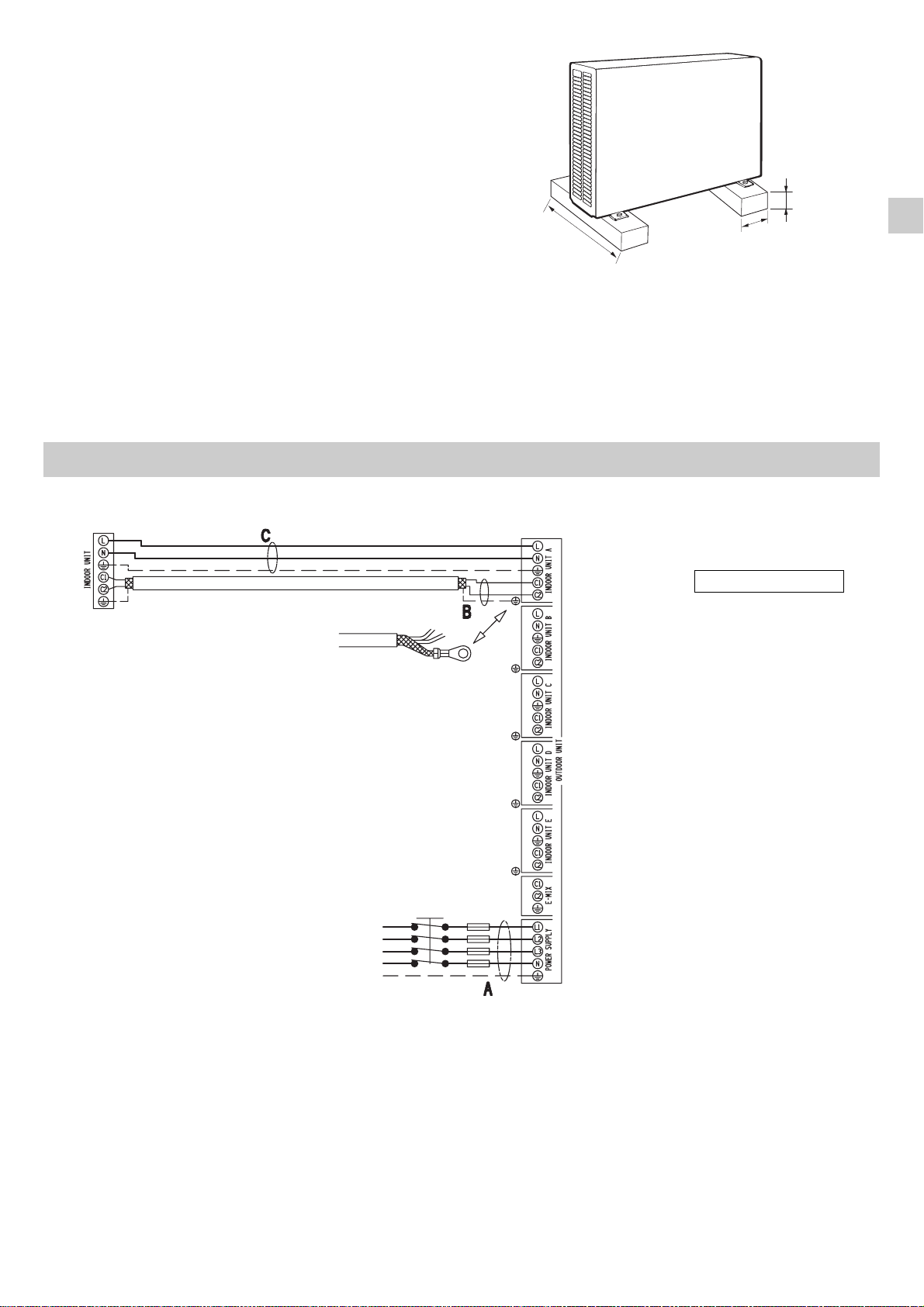
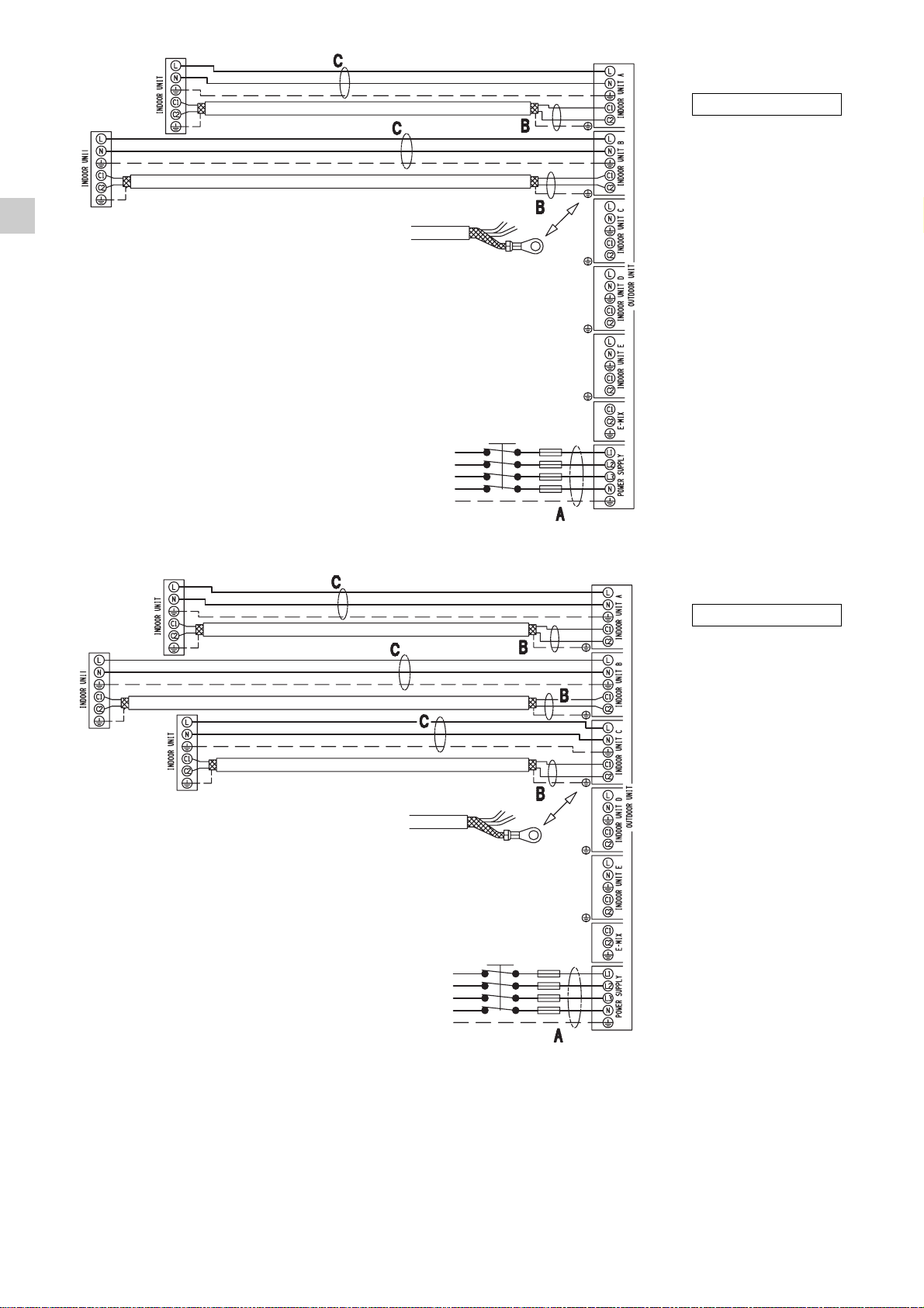
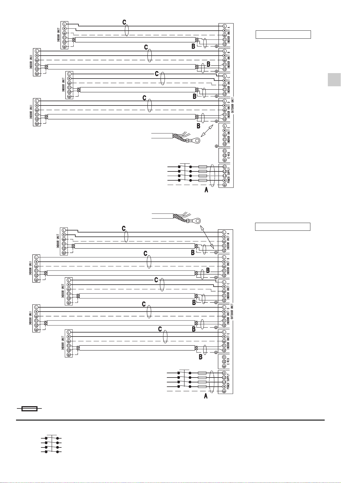
• In questo circuito elettrico vengono utilizzati voltaggi
elettrici altamente pericolosi. Fare riferimento allo schema
elettrico e a queste istruzioni durante il collegamento.
Collegamenti impropri e inadeguata messa a terra
possono causare lesioni accidentali o la morte.
•Eseguire la messa a terra dell’unità secondo le norme
elettriche locali.
• Il conduttore giallo/verde non può essere utilizzato per
collegamenti diversi dalla messa a terra.
• Fissare bene i cavi. Collegamenti inadeguati possono
causare surriscaldamento e un possibile incendio.
• I cavi elettrici non devono venire a contatto con i tubi
refrigeranti, il compressore o le parti mobili del ventilatore.
• Nel collegare l’alimentazione e le linee di controllo, non
usare cavi a più conduttori. Usare cavi separati per ciascun
tipo di linea.
Durante il trasporto
Fare attenzione nel sollevare e nello spostare le unità interna
ed esterna. È consigliabile farsi aiutare da qualcuno e
piegare le ginocchia quando si solleva per evitare strappi
alla schiena. Bordi affilati o sottili fogli di alluminio del
condizionatore potrebbero procurarvi dei tagli alle dita.
Durante l’installazione...
... A soffitto, a muro o a pavimento
Assicurarsi che siano abbastanza resistenti da reggere il
peso dell’unità. Potrebbe essere necessario costruire un
telaio in legno o metallo per provvedere a un supporto
maggiore.
... In un locale
Isolare accuratamente ogni tubazione nel locale per
prevenire formazione di condensa che potrebbe causare
gocciolamento e, di conseguenza, arrecare danni a muri e
pavimenti.
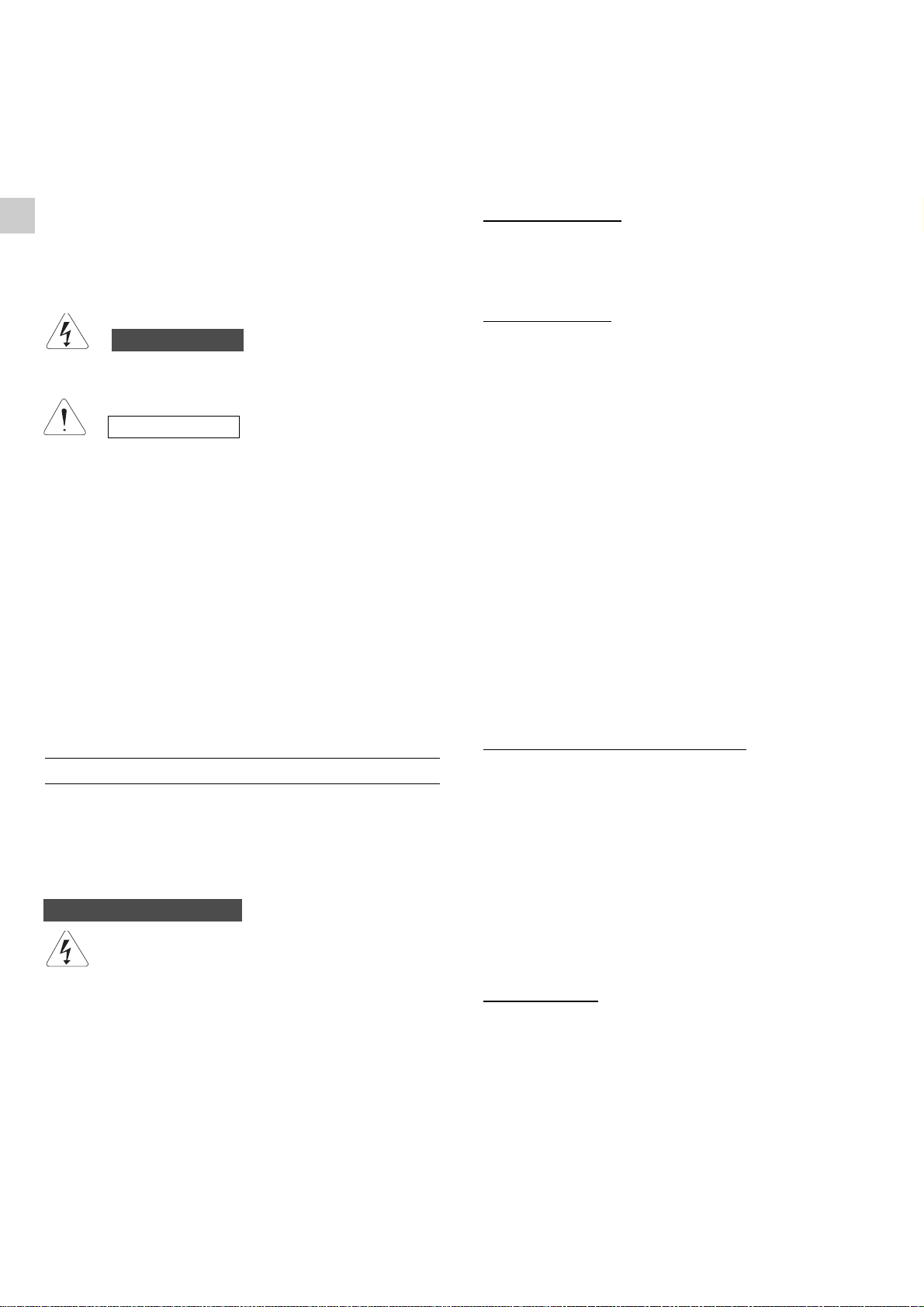
... In luoghi umidi o irregolari
Usare una base solida e rialzata dal terreno per predisporre
l’Unità Esterna.
Questo eviterà danni e vibrazioni anormali.
... In luoghi altamente ventilati
Ancorare saldamente l’unità esterna con bulloni e un telaio
in metallo. Provvedere a un adatto deflettore per l’aria.
... In luoghi soggetti a nevicate (per i condizionatori
pompa calore)
Installare l’Unità Esterna su una piattaforma più alta del livello
di accumulo della neve. Provvedere a un’apertura di sfogo
per la neve.
Collegando il circuito frigorifero
• Rispettare le indicazioni sulla lunghezza delle tubazioni.
• Usare il metodo di cartellatura per collegare i tubi.
• Oliare con olio anticongelante le superfici di contatto della
cartellatura e avvitare con le mani, quindi stringere le
connessioni utilizzando una chiave dinamometrica in
modo da ottenere un collegamento a buona tenuta.
• Verificare attentamente l’esistenza di eventuali perdite
prima della prova di funzionamento (test run).
NOTA:
Asecondo del tipo di sistema, le tubazioni per liquidi o gas
possono essere sia piccole che grandi. Per evitare
confusione, parlando di tubazione refrigerante, sarà
specificato: tubo piccolo per liquido, grande per gas.
Durante le riparazioni
• Togliere tensione (dall’interruttore generale) prima di aprire
l’unità per controllare o riparare parti elettriche.
• Tenere lontano mani e vestiti da ogni parte mobile.
• Pulire dopo aver terminato il lavoro, controllando di non
aver lasciato scarti metallici o pezzi di cavo all’interno
dell’unità.
• Areare il locale durante l’installazione e la prova del circuito
refrigerante; assicurarsi inoltre che, una volta completata
l’installazione, non si verifichino perdite di gas refrigerante
poiché il contatto con fiamme o fonti di calore può essere
tossico e molto pericoloso.
AVVERTIMENTO
PRECAUZIONE
AVVERTIMENTO
GIG

3
Scelta del luogo di installazione
EVITARE
• La vicinanza a fonti di calore o ad aree interessate da
espulsioni di aria calda.
• L’esposizione diretta al sole.
• Zone umide o soggette ad allagamenti e piano di appoggio
non livellato.
• Di eseguire fori nelle zone dove si trovano parti elettriche
o impianti.
È PREFERIBILE
• Scegliere aree possibilmente in ombra e leggermente
ventilate.
• Fissare l’unità alla base di appoggio per evitare vibrazioni.
Predisporre l'unità esterna su base solida rialzata dal terreno
e fissarla con 4 bulloni a espansione.
10 cm
10 cm
45 cm
COLLEGAMENTI ELETTRICI DEL SISTEMA
I
1 INDOOR UNIT
POWER SUPPLY
AC 380-415V
3PHASE 50Hz

GIG
4
2 INDOOR UNITS
3 INDOOR UNITS
POWER SUPPLY
AC 380-415V
3PHASE 50Hz
POWER SUPPLY
AC 380-415V
3PHASE 50Hz

5
I
4 INDOOR UNITS
5 INDOOR UNITS
FUSIBILE RITARDATO
Il dispositivo di disconnessione dalla rete di alimentazione deve avere una distanza
di apertura dei contatti che consenta la disconnessione completa nelle condizioni
della categoria di sovratensione III.
POWER SUPPLY
AC 380-415V
3PHASE 50Hz
POWER SUPPLY
AC 380-415V
3PHASE 50Hz
INTERRUTTORE ELETTRICO (SICUREZZA)

6
MATERIALE ADDIZIONALE PER L'INSTALLAZIONE (NON FORNITO)
●
Tubo in rame ricotto e disossidato per refrigerazione per il collegamento tra le unità, ed isolato con polietilene espanso di
spessore min. 8 mm.
●
Tubo in PVC per scarico condensa (ø int. 18 mm) di lunghezza sufficiente a convogliare la condensa ad uno scarico esterno.
●
Olio refrigerante per connessioni a cartella (circa 30 g.)
●
Cavo elettrico: utilizzare cavi di rame isolato del tipo, sezione e lunghezza indicati nel paragrafo “COLLEGAMENTI ELETTRICI
DEL SISTEMA”
.
LUNGHEZZA, SEZIONE CAVI E FUSIBILI RITARDATI
Cavo di alimentazione A:
Cavo elettrico multipolare; la sezione e la lunghezza del cavo elettrico consigliato sono indicate in tabella dati elettrici. Il cavo deve
essere del tipo H07RN-F (secondo CEI 20-19 CENELEC HD22). Assicurarsi che la lunghezza dei conduttori fra il punto di fissaggio
del cavo ed i morsetti sia tale che i conduttori attivi si tendano prima del conduttore di messa a terra.
Cavo di collegamento B (SCHERMATO):
Cavo elettrico bipolare schermato; la sezione e la lunghezza del cavo elettrico consigliato sono indicate in tabella
dati elettrici. Il cavo non deve essere più leggero del tipo H05VVC4V5-K (secondo CEI 20-20 CENELEC HD21).
Cavo di collegamento C (con conduttore di terra):
Cavo elettrico multipolare; la sezione e la lunghezza del cavo elettrico consigliato sono indicate in tabella dati elettrici. Il cavo non
deve essere più leggero del tipo H07RN-F (secondo CEI 20-19 CENELEC HD22).
쐽
Condizioni Massime in Raffreddamento
Temperatura esterna : 43°C B.S.
Temperatura internea: 32°C B.S. / 23°C B.U.
쐽
Condizioni Minime in Raffreddamento
Temperatura esterna : –15°C B.S.
Temperatura interna: 10°C B.S. / 6°C B.U.
쐽
Condizioni Massime in Riscaldamento
Temperatura esterna : 24°C B.S. / 18°C B.U.
Temperatura interna: 27°C B.S.
쐽
Condizioni Minime in Riscaldamento
Temperatura esterna : –15°C B.S.
Temperatura interna: 5°C B.S.
LIMITI DI FUNZIONAMENTO
GIG
MODEL
mm2
MONO SPLIT
AEI1G140 DUAL SPLIT 12,5 A
TRIAL SPLIT
QUADRI SPLIT
PENTA SPLIT
20
30
30
20
30
30
20
30
30
20
50
50
20
30
30
L ("A") m
L ("B") m
L ("C") m
4
0,75
1,5
TUBO PICCOLO TUBO GRANDE
DIMENS. UNITA’ INT. DIAMETRO ESTERNO SPESSORE MINIMO DIAMETRO ESTERNO SPESSORE MINIMO
A6,35 mm 0,8 mm 9,52 mm 0,8 mm
B - C - D 6,35 mm 0,8 mm 12,7 mm 0,8 mm
B - C - D (HK) 9,52 mm 0,8 mm 15,88 mm 1 mm
D (ASI) 9,52 mm 0,8 mm 15,88 mm 1 mm
EMIX - EMIX TANK 12,7 mm 0,8 mm 12,7 mm 0,8 mm

7
I
LIMITI SU LUNGHEZZA TUBI DI COLLEGAMENTO E DISLIVELLO
L Tot. = Lunghezza totale delle tubazioni, data dalla somma delle tubazioni di ogni singola unità interna (L1 + L2 + L3...)
Ln = Lunghezza massima delle tubazioni della singola unità interna (n=1,2,3...)
L = Mantenere le tubazioni Emix più corte possibile (MAX. 10/12m)
QUANTITA’ DI REFRIGERANTE AGGIUNTIVA
Per tubazioni 1/4 “ - 3/8” = 15g/m
Per tubazioni 1/4 “ - 1/2” = 20g/m
Per tubazioni Emix (1/2”) = 20g/m
MASSIMO DISLIVELLO - UNITA’ ESTERNA/UNITA’ INTERNA: 10m (H1, H2, H3, H4, H5, H6)
MASSIMO DISLIVELLO TRA UNITA’ INTERNE: 5m (H)
1. RIDUZIONE 1/2F - 3/8M + BOCCHETTONE 3/8 (2 pezzi)
2. RIDUZIONE 3/8F - 1/2M + BOCCHETTONE 1/2 (2 pezzi)
3. TAPPO (11 pezzi)
4. TUBO DRENAGGIO
5. AMMORTIZZATOREADESIVO (4 pezzi)
6. TUBI 1/4 - 3/8 + 1/2 - 5/8 per HK (1set)
ACCESSORI A CORREDO
1.Cacciavite a lama
2.Cacciavite medio a
stella
3.Forbici spelafili
4.Metro
5.Livella
6.Punta fresa a tazza
7.Seghetto
8.Punta da trapano ø 5
1
9.Martello
10.Trapano
11.Tagliatubi a coltello rotante
12.Flangiatubi a giogo per
attacco a cartella
13.Chiave dinamometrica
14.Chiavi fisse o a rullino
15.Sbavatore
16.Chiave esagonale
Attrezzi necessari per l’installazione (non forniti)
LUNGHEZZA MINIMA
L Tot. (m) L n (m) L Tot. (m) L n (m) L (m)
MONO SPLIT 40 - 50 - 5
DUAL SPLIT 40 30 100 30 5
AEI1G140 TRIAL SPLIT 40 30 100 30 5
QUADRI SPLIT 40 30 100 30 5
PENTA SPLIT 40 30 100 30 5
CARICA STANDARD
CARICA AGGIUNTIVA
2
4
13
5
Non è necessaria alcuna aggiunta di olio al compressore.
6
REGOLAMENTO (UE) N. 517/2014 - F-GAS
L’unità contiene R410A, un gas fluorurato a effetto serra,
con potenziale di riscaldamento globale (GWP) = 2087,50.
Non disperdere R410A nell’ambiente.
R410A: 4.40 kg / 9.19Tonn.CO2

8
GIG
Alimentazione elettrica: 380 - 415 3N ~ 50 Hz
Tipo Unità Combinazione Emix
sistema esterna n. abcdeEmix tank
1x
1b D (A2W) x
mono
G140
D (A2W)
Porta unità interna
Tipo Unità Combinazione Emix
sistema esterna n.
abcdeEmix tank
2BA x
2b D (A2W) B A x
3AAAx
3b D (A2W) A A A x
4AAAx
4b C (A2W) A A A x
5BAAx
5b C (A2W) B A A x
penta G140 6C (A2W) BAAAx
7C (A2W) AAAAx
C (A2W)
C (A2W)
D (A2W)
quadri
G140
Porta unità interna
trial
G140
D (A2W)
Tipo Unità Combinazione Emix
sistema esterna n. abcd eEmix tank
8Ax
9B
10 CC
11 CAAx
12 AA
13 C AAA
14 B AAAx
15 A AAAx
16 BAAAA
17 AAAAAx
Porta unità interna
dual
G140
D
D
quadri
G140
trial
G140
D
penta
G140
A- B- C - D = A2A taglia unità interna (vedi catalogo)
C (A2W) - D (A2W) = A2W taglia unità interna (vedi catalogo)
Tabella combinazioni unità Esterna - Interna - CONFIGURAZIONE SISTEMA
A2W
Tabella combinazioni unità Esterna - Interna - CONFIGURAZIONE SISTEMA
A2A
A2W
Tabella combinazioni unità Esterna - Interna - CONFIGURAZIONE SISTEMA
A2A
A2A = modelli aria-aria
A2W = modelli aria-acqua
x=combinazione con Emix/ Emix tank possibile

9
(continua a pag. 10)
DICHIARAZIONE DI CONFORMITÀ
Questo prodotto è marcato in quanto conforme alle Direttive:
–Bassa Tensione n. 2006/95/CE (Standard: EN60335-2-40:2003 (incl. Corr.:2006) + A11:2004 +A12:2005 + A13:2012
+ A1:2006 +A2:2009 with EN 60335-1:2002 + A11:2004 + A1:2004 +A12:2006 + A2:2006 +A13:2008 + A14:2010 +
A15:2011).
–Compatibilità Elettromagnetica n. 2004/108/CE, 92/31 CEE e 93/68 CEE. (Standard: EN55014-1 (2006) + A1(2009)
+ A2(2011), EN 55014-2 (1997) + A1(2001) + A2 (2008), EN 61000-3-2 (2006) + A1(2009) + A2(2009),
EN 61000-3-3 (2008)
–RoHS2 n.2011/65/UE.
–Regolamento (UE) n. 206/2012, del 6 marzo 2012, relativo alle specifiche per la progettazione ecocompatibile dei
condizionatori d’aria e dei ventilatori.
–Regolamento (UE) n. 626/2011, del 4 maggio 2011, relativo all’etichettatura indicante il consumo d’energia dei
condizionatori d’aria.
Questa dichiarazione sarà nulla nel caso di impiego diverso da quello dichiarato dal Fabbricante e/o di mancata
osservanza, anche solo parziale, delle istruzioni d'installazione e/o d'uso.
I

2
IMPORTANT!
Veuillez lire ce qui suit avant de commencer
Ce système de conditionnement de l'air répond à des
normes strictes de fonctionnement et de sécurité. En tant
qu'installateur ou ingénieur de maintenance, une partie
importante de votre travail est d'installer ou d'entretenir le
système de manière à ce qu'il fonctionne efficacement en
toute sécurité.
Pour effectuer une installation sûre et obtenir un
fonctionnement sans problème, il vous faut:
• Lire attentivement cette brochure d'information avant de
commencer.
• Procéder à chaque étape de l'installation ou de la
réparation exactement comme il est indiqué.
• Respecter toutes les réglementations électriques locales,
régionales et nationales.
• Observer toutes les recommandations de prudence et
de sécurité données dans cette notice.
• Pour l'alimentation de l'appareil utiliser une ligne électrique
dédiée.
Ce symbole fait référence à une pratique dangereuse ou
imprudente qui peut entraîner des blessures personnelles
ou la mort.
Ce symbole fait référence à une pratique dangereuse ou
imprudente qui peut entraîner des blessures personnelles
ou des dégâts matériels, soit à l'appareil, soit aux
installations.
Si nécessaire, demandez que l'on vous prête assistance
Ces instructions suffisent à la plupart des sites d'installation
et des conditions de maintenance. Si vous avez besoin
d'assistance pour résoudre un problème particulier,
adressez-vous à notre service aprés vente ou à votre
revendeur agréé pour obtenir des instructions
supplémentaires.
Dans le cas d'une installation incorrecte
Le fabricant ne sera en aucun cas responsable dans le cas
d'une installation ou d'une maintenance incorrecte, y compris
dans le cas de non-respect des instructions contenues dans
ce document.
PRECAUTIONS PARTICULIERES
• Pour l’installation: raccorder les liaisons frigorifiques, puis
les liaisons électriques.
Pour le démontage: procéder de manière inverse.
Lors du câblage
UNE DECHARGE ELECTRIQUE PEUT
ENTRAINER UNE BLESSURE PERSONNELLE
GRAVE OU LA MORT. SEUL UN ELECTRICIEN
QUALIFIE ET EXPERIMENTE DOIT EFFECTUER
LE CABLAGE DE CE SYSTEME.
• Ne mettez pas l'appareil sous tension tant que tout le
système de câbles et de tuyaux n'est pas terminé ou
rebranché et vérifié, pour assurer la mise à la terre.
• Des tension électriques extrêmement dangereuses sont
utilisées dans ce système. Veuillez consulter attentivement
le schéma de câblage et ses instructions lors du câblage.
Des connexions incorrectes ou une mise à la terre inadéquate
peuvent entraîner des blessures accidentelles ou la mort.
•Effectuez la mise à la terre de l'appareil en respectant
les réglementations électriques locales.
• Le câble jaune/vert ne peut en aucun cas être utilisé pour
toute autre connexion que celle de la mise à la terre.
• Serrez fermement toutes les connexions. Un câble mal
fixé peut entraîner une surchauffe au point de connexion
et présenter un danger potentiel d'incendie.
• Il ne faut en aucun cas laisser les câbles toucher la
tuyauterie du réfrigérant, le compresseur ou toute pièce
mobile.
• N’utilisez pas de câble multiconducteur pour le câblage
des lignes d’alimentation électrique et celles de
commande. Utilisez des câbles séparés pour chaque type
de ligne.
Lors du transport
Soyez prudent lorsque vous soulevez et déplacez les
appareils intérieur et extérieur. Demandez à un collègue
de vous aider, et pliez les genoux lors du levage afin de
réduire les efforts sur votre dos. Les bords acérés ou les
ailettes en aluminium mince se trouvant sur le climatiseur
risquent de vous entailler les doigts.
Lors de l'installation...
... dans un plafond ou un mur
Assurez-vous que le plafond ou le mur sont suffisamment
solides pour supporter le poids de l'appareil. Il peut être
nécessaire de construire un solide châssis en bois ou en
métal pour offrir un support supplémentaire.
... dans une pièce
Isolez correctement tout tuyau circulant à l'intérieur d'une
pièce pour éviter que de la condensation ne s'y dépose et
ne goutte, ce qui pourrait endommager les murs et les
planchers.
... dans des endroits humides ou sur des surfaces
irrégulières
Utilisez une plate-forme surélevée pour offrir une base
solide et régulière à l'appareil extérieur.
Ceci permettra d'éviter des dégâts causés par l'eau et des
vibrations anormales.
... dans une zone exposée à des vents forts
Ancrez solidement l'appareil extérieur avec des boulons et
un châssis en métal. Réalisez un déflecteur efficace.
... dans une zone neigeuse (pour le système du type
reversible)
Installez l'appareil extérieur sur une plate-forme surélevée
à un niveau supérieur à l'amoncellement de la neige.
Réalisez des évents à neige.
Lors de la connexion des tuyaux de réfrigération
• Respecter les informations sur la longueur des tuyaux.
• Les raccordements sont de type flare.
• Appliquez de l’huile frigorifique sur les surfaces de contact
avant de les connecter, puis serrez l'ecrou avec une clé
dynamométrique pour effectuer une connexion sans fuite.
• Recherchez soigneusement la présence de fuites avant
d'effectuer l'essai de fonctionnement.
NOTE:
Selon le type du système, les tuyaux de gaz et de liquide
peuvent être petits ou gros. Par conséquent, afin d'éviter
toute confusion, le tuyau de réfrigérant de votre modèle
particulier est dénommé "petit" pour le liquide et "gros" pour
le gaz.
Lors de la maintenance
• Interrompre l'alimentation électrique sur le commutateur
principal avant d'ouvrir l'appareil pour vérifier ou réparer
le câblage et les pièces électriques.
• Veillez à maintenir vos doigts et vos vêtements éloignés
de toutes les pièces mobiles.
• Nettoyez le site lorsque vous avez fini, en pensant à
vérifier que vous n'avez laissé aucune ébarbure de métal
ou morceau de câble à l'intérieur de l'appareil dont vous
avez effectué la maintenance.
• Aèrez la pièce pendant l'installation et l'essai du circuit
réfrigérant; assurez-vous que, après l'installation, des
fuites de gaz réfrigérant ne se produisent pas, puisque
le contact avec des flammes ou des sources de chaleur
peut être toxique et très dangereux.
DANGER
ATTENTION
DANGER
FG

3
Choix de l'emplacement d'installation
EVITEZ
• Les sources de chaleur, les ventilateurs d'évacuation,
etc.
• La lumière directe du soleil.
• Les endroits mouillés, humides ou de surface irrégulières.
• De faire des trous où il y a des câbles électriques ou des
conduits.
RECHERCHEZ
• Un emplacement aussi frais que possible et bien ventilé.
• Utilisez des boulons ou similaire pour fixer l'appareil, afin
d'en réduire le bruit et les vibrations.
Mettre l'unité extérieure sur une base solide degagée du sol
et la fixer à l'aide de 4 faire-fond.
10 cm
10 cm
45 cm
BRANCHEMENTS ELECTRIQUES DU SYSTEME
GF
1 INDOOR UNIT
POWER SUPPLY
AC 380-415V
3PHASE 50Hz

4
FG
2 INDOOR UNITS
3 INDOOR UNITS
POWER SUPPLY
AC 380-415V
3PHASE 50Hz
POWER SUPPLY
AC 380-415V
3PHASE 50Hz
This manual suits for next models
1
Table of contents
Languages:
Other Argo Air Conditioner manuals

Argo
Argo CLIMIA CMK 4000 WiFi User manual

Argo
Argo CHARM Series User manual

Argo
Argo MADISON User manual

Argo
Argo Relax User manual

Argo
Argo ECOWALL 9000 UI User manual

Argo
Argo KENNY EVO User manual

Argo
Argo AS1S** Series User manual

Argo
Argo Extreme 9 User manual

Argo
Argo AFSI ECO 120SH3 User manual

Argo
Argo POLIFEMO SLIM User manual