Argo AUR210CL Series Manual

TECHNICAL DATA & SERVICE MANUAL
ROOM AIR CONDITIONER WITH REMOTE CONDENSER
TEST OFF ON
- AUR210CLXXXX
- AU213CLXXXX
- AUR310HLXXX
COOLING ONLY VERSION(R407C)
HEAT PUMP VERSION(R407C)
0.8180.090.1 05/2000

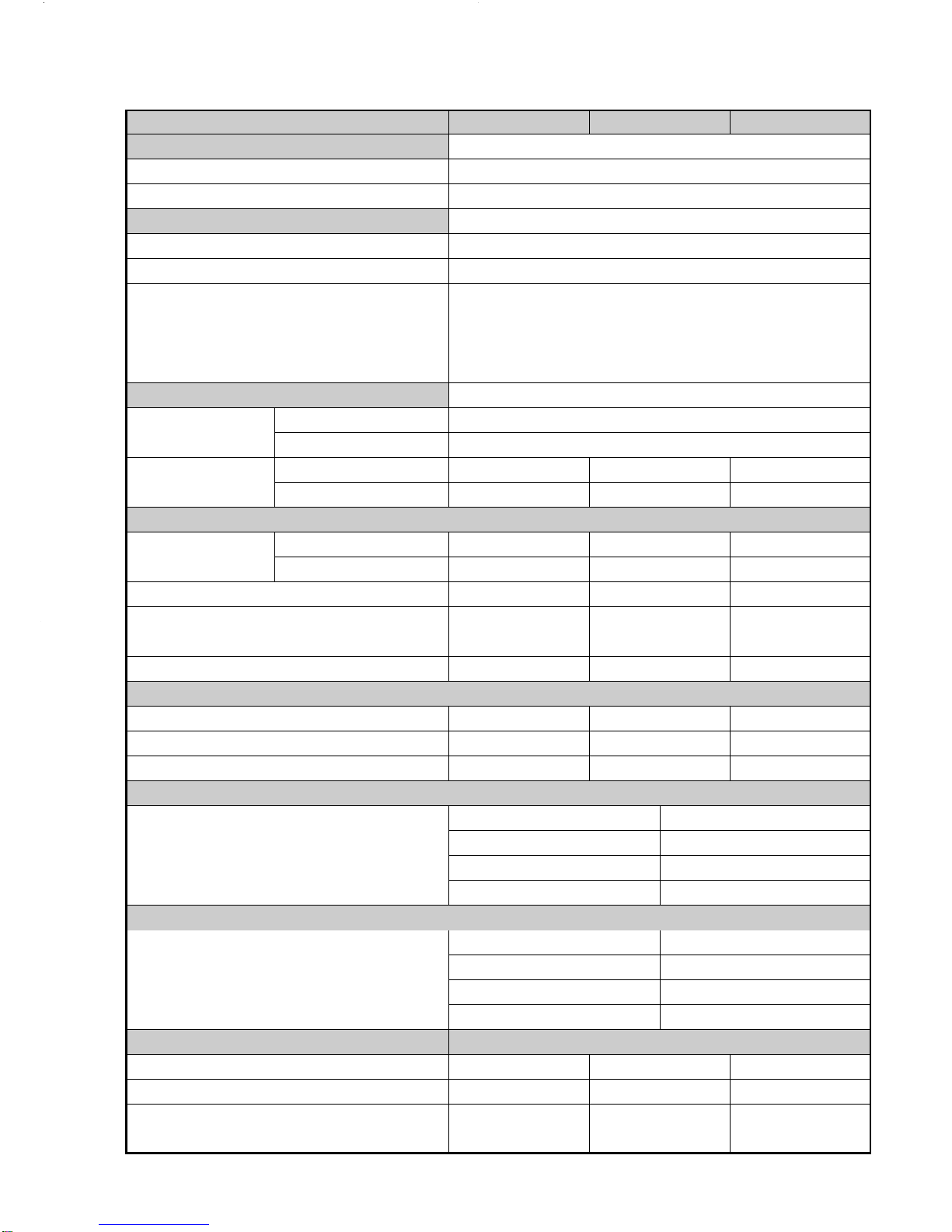
SPECIFICATIONS.................................................................................................................................................
1) Unit Specifications . . . . . . . . . . . . . . . . . . . . . . . . . . . . . . . . . . . . . . . . . . . . . . . . . . . . . . . . . . . . . . . . . . . . . . . . . . . . . . . . . . . . . . . . . . . . . . . . . . . . . . . . . . . . . . . . . . . . . . . . . . . . . . . . . . . . . . . . . . . . .
2) Major Components Specifications
a) Indoor Unit . . . . . . . . . . . . . . . . . . . . . . . . . . . . . . . . . . . . . . . . . . . . . . . . . . . . . . . . . . . . . . . . . . . . . . . . . . . . . . . . . . . . . . . . . . . . . . . . . . . . . . . . . . . . . . . . . . . . . . . . . . . . . . . . . . . . . . . . . . . . . . . . . .
b) Outdoor Unit (little bag) . . . . . . . . . . . . . . . . . . . . . . . . . . . . . . . . . . . . . . . . . . . . . . . . . . . . . . . . . . . . . . . . . . . . . . . . . . . . . . . . . . . . . . . . . . . . . . . . . . . . . . . . . . . . . . . . . . . . . . . . . . . . . .
OPERATING RANGE . . . . . . . . . . . . . . . . . . . . . . . . . . . . . . . . . . . . . . . . . . . . . . . . . . . . . . . . . . . . . . . . . . . . . . . . . . . . . . . . . . . . . . . . . . . . . . . . . . . . . . . . . . . . . . . . . . . . . . . . . . . . . . . . . . . . . . . . . . .
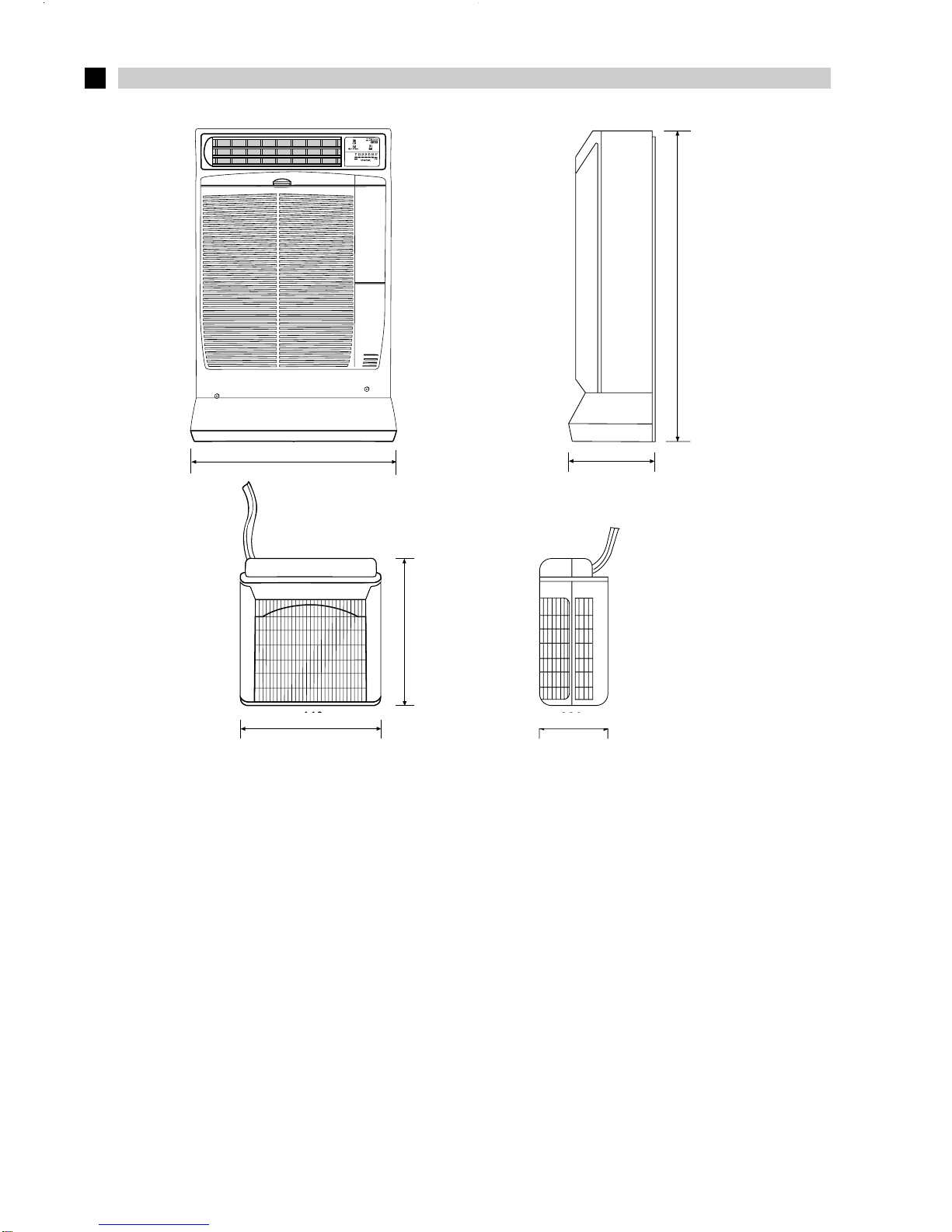
DIMENSIONAL DATA. . . . . . . . . . . . . . . . . . . . . . . . . . . . . . . . . . . . . . . . . . . . . . . . . . . . . . . . . . . . . . . . . . . . . . . . . . . . . . . . . . . . . . . . . . . . . . . . . . . . . . . . . . . . . . . . . . . . . . . . . . . . . . . . . . . . . . . . . . .
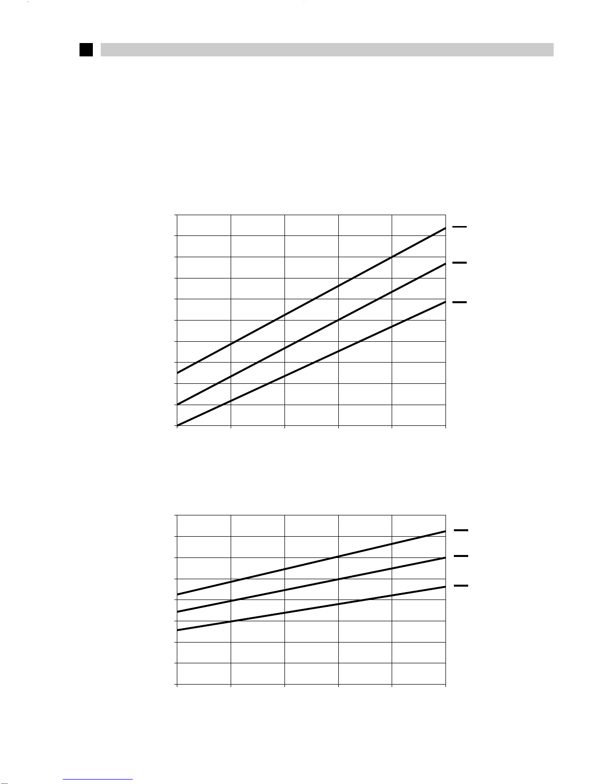
PERFORMANCE CHARTS (operating current) . . . . . . . . . . . . . . . . . . . . . . . . . . . . . . . . . . . . . . . . . . . . . . . . . . . . . . . . . . . . . . . . . . . . . . . . . . . . . . . . . . . . . . . . . . . . . . . . . . .
REFRIGERANT FLOW DIAGRAM.......................................................................................................................
FUNCTION..................................................................................................................................................
1) Room temperature control (cooling and heating) . . . . . . . . . . . . . . . . . . . . . . . . . . . . . . . . . . . . . . . . . . . . . . . . . . . . . . . . . . . . . . . . . . . . . . . . . . . . . . . . . . . . . . . . . . . . . .
2) Freeze prevention (cooling) . . . . . . . . . . . . . . . . . . . . . . . . . . . . . . . . . . . . . . . . . . . . . . . . . . . . . . . . . . . . . . . . . . . . . . . . . . . . . . . . . . . . . . . . . . . . . . . . . . . . . . . . . . . . . . . . . . . . . . . . . . . . . .
3) Overload prevention (heating) . . . . . . . . . . . . . . . . . . . . . . . . . . . . . . . . . . . . . . . . . . . . . . . . . . . . . . . . . . . . . . . . . . . . . . . . . . . . . . . . . . . . . . . . . . . . . . . . . . . . . . . . . . . . . . . . . . . . . . . . . .
4) Dry operation (dehumidification) . . . . . . . . . . . . . . . . . . . . . . . . . . . . . . . . . . . . . . . . . . . . . . . . . . . . . . . . . . . . . . . . . . . . . . . . . . . . . . . . . . . . . . . . . . . . . . . . . . . . . . . . . . . . . . . . . . . . . . .
5) Automatic switching between cooling and heating . . . . . . . . . . . . . . . . . . . . . . . . . . . . . . . . . . . . . . . . . . . . . . . . . . . . . . . . . . . . . . . . . . . . . . . . . . . . . . . . . . . . . . . . . . .
6) Defrosting operation (heating) . . . . . . . . . . . . . . . . . . . . . . . . . . . . . . . . . . . . . . . . . . . . . . . . . . . . . . . . . . . . . . . . . . . . . . . . . . . . . . . . . . . . . . . . . . . . . . . . . . . . . . . . . . . . . . . . . . . . . . . . . .
7) Defrosting mode timing chart. . . . . . . . . . . . . . . . . . . . . . . . . . . . . . . . . . . . . . . . . . . . . . . . . . . . . . . . . . . . . . . . . . . . . . . . . . . . . . . . . . . . . . . . . . . . . . . . . . . . . . . . . . . . . . . . . . . . . . . . . . . . .
ELECTRICAL DATA.............................................................................................................................................
TROUBLE SHOOTING...........................................................................................................................................
Check before and after «Troubleshooting»
a) Check power supply wiring . . . . . . . . . . . . . . . . . . . . . . . . . . . . . . . . . . . . . . . . . . . . . . . . . . . . . . . . . . . . . . . . . . . . . . . . . . . . . . . . . . . . . . . . . . . . . . . . . . . . . . . . . . . . . . . . . . . . . . . .
b) Check power supply . . . . . . . . . . . . . . . . . . . . . . . . . . . . . . . . . . . . . . . . . . . . . . . . . . . . . . . . . . . . . . . . . . . . . . . . . . . . . . . . . . . . . . . . . . . . . . . . . . . . . . . . . . . . . . . . . . . . . . . . . . . . . . . . . . .
Circuit breaker trips (or fuse blows) . . . . . . . . . . . . . . . . . . . . . . . . . . . . . . . . . . . . . . . . . . . . . . . . . . . . . . . . . . . . . . . . . . . . . . . . . . . . . . . . . . . . . . . . . . . . . . . .
Circuit breaker trips in several minutes after turning air conditioner ON . . . . . . . . . . . . . . . . . . . . . . . . . . . . . . . . . . . . . . . .
Water - level alarm (lamp) is flashing . . . . . . . . . . . . . . . . . . . . . . . . . . . . . . . . . . . . . . . . . . . . . . . . . . . . . . . . . . . . . . . . . . . . . . . . . . . . . . . . . . . . . . . . . . . . .
Outdoor unit and compressor do not run . . . . . . . . . . . . . . . . . . . . . . . . . . . . . . . . . . . . . . . . . . . . . . . . . . . . . . . . . . . . . . . . . . . . . . . . . . . . . . . . . . . . . . . .
Some part of air conditioner does not operate . . . . . . . . . . . . . . . . . . . . . . . . . . . . . . . . . . . . . . . . . . . . . . . . . . . . . . . . . . . . . . . . . . . . . . . . . . . . . . .
Air conditioner operates, but abnormalitis are observed . . . . . . . . . . . . . . . . . . . . . . . . . . . . . . . . . . . . . . . . . . . . . . . . . . . . . . . . . . . . . . . .
Poor cooling or poor heating . . . . . . . . . . . . . . . . . . . . . . . . . . . . . . . . . . . . . . . . . . . . . . . . . . . . . . . . . . . . . . . . . . . . . . . . . . . . . . . . . . . . . . . . . . . . . . . . . . . . . . . . . .
Excessive cooling or heating . . . . . . . . . . . . . . . . . . . . . . . . . . . . . . . . . . . . . . . . . . . . . . . . . . . . . . . . . . . . . . . . . . . . . . . . . . . . . . . . . . . . . . . . . . . . . . . . . . . . . . . . . .
Indoor coil and room temperature thermistores (TH1 - TH2) are defective . . . . . . . . . . . . . . . . . . . . . . . . . . . . . . . . . . . .
PROCEDURE TO RELOAD THE REFRIGERANT CHARGE IN THE UNIT....................................................... 26
CHECKING ELECTRICAL COMPONENTS......................................................................................................... 28
1) Measurement of insulation resistance . . . . . . . . . . . . . . . . . . . . . . . . . . . . . . . . . . . . . . . . . . . . . . . . . . . . . . . . . . . . . . . . . . . . . . . . . . . . . . . . . . . . . . . . . . . . . . . . . . . . . . . .
a) Power supply wires . . . . . . . . . . . . . . . . . . . . . . . . . . . . . . . . . . . . . . . . . . . . . . . . . . . . . . . . . . . . . . . . . . . . . . . . . . . . . . . . . . . . . . . . . . . . . . . . . . . . . . . . . . . . . . . . . . . . . . . . . . . . . . . . . . . .
b) Indoor unit. . . . . . . . . . . . . . . . . . . . . . . . . . . . . . . . . . . . . . . . . . . . . . . . . . . . . . . . . . . . . . . . . . . . . . . . . . . . . . . . . . . . . . . . . . . . . . . . . . . . . . . . . . . . . . . . . . . . . . . . . . . . . . . . . . . . . . . . . . . . . . . . . . .
c) Measurement of insulation resistance for electrical parts . . . . . . . . . . . . . . . . . . . . . . . . . . . . . . . . . . . . . . . . . . . . . . . . . . . . . . . . . . . . . . . . . . . . . . . . . .
2) Checking continuity of fuse on PCB Ass’y . . . . . . . . . . . . . . . . . . . . . . . . . . . . . . . . . . . . . . . . . . . . . . . . . . . . . . . . . . . . . . . . . . . . . . . . . . . . . . . . . . . . . . . . . . . . . . . . .
3) Checking motor capacitor . . . . . . . . . . . . . . . . . . . . . . . . . . . . . . . . . . . . . . . . . . . . . . . . . . . . . . . . . . . . . . . . . . . . . . . . . . . . . . . . . . . . . . . . . . . . . . . . . . . . . . . . . . . . . . . . . . . . . . . . . .
TABLE OF CONTENTS
A
B
C
D
E
F
G
H
I
A
B
C
D
E
F
G
H
I
L
pag.
3/4/5/6
6
7
8/9
10
FROM 11 TO 16
17/18
19

3
Controls / temperature control Microprocessor / I.C. Thermostat
Control unit Wireless remote control unit
Timer ON / OFF 24 hours and program
Fan speed indoor / outdoor 3 and auto / 1
Horizontal Manual
Vertical Manual
Air filter Washable, easy access
Compressor Rotary (hermetic)
Refrig./Stand. charge at shipment g 910 1220 1030
Tot. refrig. charge with 2 m extension g 960 1270 1090
Tot. refrig. charge with 4 m extension g 1010 1320 1150
Refrigerant control Capillary tube
Idoor Hi/Me/Lo dB-A
44 / 40 / 39 46 / 42 / 41 44 / 40 / 39
Outdoor Hi dB-A 54 51 51
Stand. tubing length m ~ 2,5
Tubing length with 2 m extension kit m ~ 4,5
Tubing length with 4 m extension kit m ~ 6,5
DIMENSIONS AND WEIGTH UNIT DIMENSIONS
Indoor unit Height mm 790
Width mm 580
Depth mm 245
Outdoor unit Height mm 435 490 490
Width mm 440 525 525
Depth mm 230 250 250
Net weight / indoor unit - outdoor unit kg 44 / 9,5 44 / 15 44 / 15
PERFORMANCES COOLING COOLING HEATING
Voltage rating V 220 ÷240
Available voltage range V 198 ÷264
Running ampere A 4,4 6.2 4.2 4.3
Power input W 980 1300 940 950
Power factor % 0,96 0,91 0,97 0,96
C.O.P. W/W 2.70 2.82 2.98 3,31
Compressor locked rotor amperes A 23 34 23
Power source V
220 - 240 ~ 50Hz
BTU / h 9500 12500 9820 10700
W (Kcal / h) 2650 (2270) 3670 (3150) 2800 (2400) 3140 (2700)
Air circulation (high/med/low) m3 / h 370/340/270 450/400/340 370/340/270
Moisture removal (high speed) l / h 1,2 1,5 1,2
UNIT MODEL
Capacity
Airflow direction
(Indoor)
Livello rumore
AUR210CLXXX AUR213CLXXX AUR310HLXXX
1) UNIT SPECIFICATIONS
NOTA
Rating conditions:
Cooling: outside air temp.: 35°C DB, indoor unit entering air temp.: 27 °C DB, 19 °C WB
Heating: outside air temp.: 7°C DB, 6 °C WB, indoor unit entering air temp.: 20 °C DB
Data subject to change without notice.
ASPECIFICATIONS
FEATURES
ELECTRICAL RATINGS

4
SAFETY DEVICES
FAN & FAN MOTOR
CONTROLLER P.C.B.
MODEL AUR210CLXXX AUR213CLXXX AUR310HLXXX
Primary AC 235 V - 50 Hz AC 235 V - 50 Hz AC 235 V - 50 Hz
Secondary 11 V - 0,727 A 11 V - 0,727 A 19 V - 0,526 A
Capacity 8 VA 8 VA 10 VA
Coil resistance (at 22 °C)
Primary Ω
WHT - WHT: 214 ±10% WHT - WHT: 214 ±10% WHT
-
WHT
: 205
±
10%
Secondary
BRN - BRN: 1,58 ±20% BRN - BRN: 1,58 ±20% BRN
-
BRN
: 2,0
±
10%
Thermal cutoff temp. 145 °C - 2A 145 °C - 2A 145 °C - 2A 150 °C
Coil rated AC 230 V AC 220 V AC 24 V
Coil resistance (at 20 °C) KΩ 7.250 ±10% 21 ±15% 650 ±10%
Contact rated AC 250 V - 30A AC 220 V - 25A
AC 25 V - 20A - L.R.A. 60A
Resistance kΩ -20 °C 40,1 ±5% 20 °C 6,5 ±5%
-10 °C 24,4 ±5% 30 °C 4,4 ±5%
0 °C 15,3 ±5% 40 °C 3,0 ±5%
10 °C 9,9 ±5% 50 °C 2,1 ±5%
Resistance kΩ 10 °C 10,0 ±4% 30 °C 4,0 ±4%
15 °C 7,9 ±4% 35 °C 3,3 ±4%
20 °C 6,3 ±4% 40 °C 2,7 ±4%
25 °C 5,0 ±4% 50 °C 1,8 ±4%
COMPRESSOR....(Rotary hermetic)
Controls Microprocessor
Control circuit fuse 250V - 3A
Cross - flow
Number ... dia. / Lenght mm 1 ... ø 100 / L 410
Nominal output W 27
Coil resistance Ω
GRY - WHT: 545 ÷ 630
(Ambient temp. 25 °C)
WHT - VLT: 92 ÷ 105
VLT - YEL: 62 ÷ 71
YEL - BRN: 780 ÷ 900
Internal thermo fuse
Open °C 150 ±10
Close °C Automatic reclosing
µF 1,0 1,5 1,0
VAC 440 440 440
THERMISTOR (COIL SENSOR) TH1
TRANSFORMER
POWER RELAY (COMPRESSOR)
Nominal outpot W 950 1290 950
Compressor oil cc 500 550 500
Coil resistance Ω C - R: 3,01 ±7% C - R: 1.92 ±
7% C - R: 3,01 ±7%
(Ambient temp. 20 °C) C - S: 7,82 ±7% C - S: 5.29 ±7% C - S: 7,82 ±7%
Rated
2) MAJOR COMPONENT SPECIFICATIONS
a) INDOOR UNIT
Operating
temp.
Run capacitor
THERMISTOR (ROOM SENSOR) TH2
80228245B 80228245B
80235245B

Coil rating — — AC 240 - 50Hz - 6W
Coil resistance (at 20 °C) Ω— — 1740
±7%
Coil Aluminium plate fin / Copper tube
Rows 2
Fin pitch mm 1,8
Face area m20,185
5
Operating amp. Trip in
(Ambient temp. 25°C) 6 ÷16 sec. at 22,5A
SAFETY DEVICES
Coil rating AC 300V - 50Hz
Coil resistance (at 23 °C) KΩ13,3 ± 2%
Contact rating 20A CA
Operating voltage AC 185 ÷ 217V - 50Hz
Operating voltage AC 60 ÷ 120V - 50Hz
Operating amp. Trip in Trip in Trip in
(Ambient temp. 25°C) 6 ÷16 sec. at 16A 6 ÷16 sec. at 22,5A 6 ÷16 sec. at 16A
Rating AC 220 / 240 V 50Hz
Delayed time (OFF) from 3 to 5 minutes
Overload relay (OLR1) External type
Operating temp. Open °C 115 ±4%
Close °C 95 ±10%
MODEL AUR210CLXXX AUR213CLXXX AUR310HLXXX
Overload relay (OLR) External type
Operating temp. Open °C 140 ±5% 135 ±7% 140 ±5%
Close °C 69 ±11% 69 ±11% 69 ±11%
µF—56—
VAC — 330 —
Run capacitor - C4
Rating AC 230V - 50Hz
Nominal output W 12 ±10%
Coil resistance
(Ambient temp. 20 °C) Ω122
Operating amp. Trip in
(Ambient temp. 25°C) 6 ÷16 sec. at 22,5A
Operations high: open
low: close
Induttance mH 14 ÷ 19 A/50Hz
Coil resistance (at 20 °C) KW0,69 ± 5%
µF 20 25 20
VAC 450 450 450
Run capacitor - C3
Controls — — Microprocessor
Control circuit fuse — — 250V - 3A
PUMP DELAYING DEVICE (CRP) (95 VERSION)
STARTING RELAY (RA)
CURRENT LIMITER (LC)
DRAIN PUMP
CONTROLLER P.C.B. (DEFROST)
FLOAT SWITCH (PUMP)
SOLENOID VALVE (4 - way valve)
HEAT EXCH. COIL
Overload relay (OLR2) External type
Temperatura di intervento Open °C 150 ±7%
Close °C 69 ±11%

6
INDOOR UNIT OUTDOOR UNIT
Number ... Dia. (mm) 1.... ø 320 1.... ø 380 1.... ø 380
No. of pole .... rpm (220V, high) 6 ....... 860 6 ....... 860 6 ....... 860
Nominal output W 58 70 70
Coil resistance Ω
BLU - BRN: 249 ÷ 287 BLU - BRN: 218 ÷ 251 BLU - BRN: 218 ÷ 215
(Ambient temp. 25 °C) BLU - BLK : 270 ÷ 311 BLU - BLK
:
230 ÷ 265 BLU - BLK
:
230 ÷ 265
Coil Aluminum plate fin / Copper tube
Rows 2 2 2
Fin pitch mm 1,6 1,6 1,6
Face area m20,255 0,3 0,3
SAFETY DEVICES Internal type
THERMOSTAT (DEFROST THERMO.)
HEAT EXCH. COIL
Temperature
Temperature air °C intake temp. Temperature air °C intake temp.
Maximum 32 °C DB / 22 °C WB 46 °C DB
Minimum 19 °C DB / 14 °C WB 19 °C DB
Maximum 27 °C DB / 19 °C WB 24 °C DB / 18 °C WB
Minimum - DB / - WB -8 °C DB / -9 °C WB
Open °C 150 ±10%
Close °C Automatic reclosing
µF 2 2,5 2,5
VAC 450 450 450
Operating temp.
Run capacitor
MODEL AUR210CLXXX AUR213CLXXX AUR310HLXXX
Temperature Temperature air °C Temperature air °C
intake temp. intake temp.
Maximum 32 °C DB / 23 °C WB 46 °C DB
Minimum 19 °C DB / 14 °C WB 19 °C DB
B OPERATING RANGE COOLING MODELS
OPERATING RANGE HEAT PUMP MODELS
FAN & FAN MOTOR
Proppeler Proppeler Proppeler
Operating temp. — —
ON - Close 12 ± 2 Diff. + 0/8 °C
Contact rating — —
AC 120 V 0,5A
b) OUTDOOR UNIT (LITTLE BAG)
Cooling
Cooling
Heating

7
CDIMENSIONAL DATA
Indoor unit
Outdoor unit
580
835
245
230
440
425
DIMENSIONS: mm
* HEAT PUMP MODEL AND AUR213CLXXX
790
580
440 (* 490) 230 (* 250)
435 (* 490)
245

8
5.2
5.0
4.8
4.6
4.4
4.2
4.0
3.8
3.6
3.4
3.2
DPERFORMANCE CHARTS
20
OPERATING CURRENT - A
25
32
30 35 40 45
27
19
7.0
6.5
6.0
5.5
5.0
4.5
4.0
3.5
3.0
OPERATING CURRENT - A
OUTDOOR INLET AIR D.B. TEMP. (°C)
20 25 30 35 40 45
OUTDOOR INLET AIR D.B. TEMP. (°C)
AUR213CLXXX
AUR210CLXXX
32
27
19
Operating characteristics versus outdoor ambient temperature and indoor temperature.
Conditions: Power source 230 V - 1 - 50Hz - Single phase
Indoor air velocity High
Refrigerant Amount charged at shipment
Tubing length 2,5 m
Cooling characteristics
Indoor relative humidity 46%
INDOOR INLET AIR D.B. TEMP. (°C) INDOOR INLET AIR D.B. TEMP. (°C)

9
…
32
27
19
5.5
5.0
4.5
4.0
3.5
3.0-10 -5 0 5 10 15 20 25
……
24
20
18
…
…
…
5.2
5.0
4.8
4.6
4.4
4.2
4.0
3.8
3.6
3.4
3.2
3.0
OPERATING CURRENT - A
OUTDOOR INLET AIR D.B. TEMP. (°C)
INDOOR INLET AIR D.B. TEMP. (°C)
OPERATING CURRENT - A
OUTDOOR INLET AIR D.B. TEMP. (°C)
INDOOR INLET AIR D.B. TEMP. (°C)
20 25 30 35 40 45
Operating characteristics versus outdoor ambient temperature and indoor temperature.
Conditions: Power source 230 V - 1 - 50Hz
Indoor air velocity High
Refrigerant Amount charged at shipment
Tubing length 2,5 m
Cooling characteristics
Indoor relative humidity 46%
HEAT PUMP MODELS
Heating
Outdoor relative humidity 85%

10
E REFIGERANT FLOW DIAGRAM COOLING MODELS
QUICK
CONNECTOR
CAPILLARY
TUBE Compressor Accumulator
Mechanical filter
Heat exchanger
Heat exchanger
Outdoor unit Indoor unit
REFIGERANT FLOW DIAGRAM HEAT PUMP MODELS
Heat exchanger
Muffler
Stainer
4-way valve
Accumulator
Compressor
Heat exchanger
Drier
Capillary tube Capillary tube
Check
valve
( )
Indoor unit
Outdoor unit
Quick connector
Cooling cycle
Heating cycle

11
NOTA
●The control circuit will not attempt to turn the compressor ON until the compressor has been OFF for at least
3 minutes. To protect the compressor from stalling out when trying to start against the high side refrigerant
pressure, the control circuit has a built-in automatic time delay to allow the internal pressure to equalize.
●As a protective measure, the control circuit switches the compressor OFF after 5 minutes or more of com-
pressor operation.
●Thermo ON: When the room temperature is above T + 1 °C (T°C is set temperature).
Compressor
➜
ON.
●Thermo OFF: When the room temperature in equal to or below set temperature T°C.
Compressor
➜
OFF.
FFUNCTION
1) ROOM TEMPERATURE CONTROL
Cooling
●Room temperature control is obtained by cycling the compressor ON and OFF under control of the room
temperature sensor in the remote control unit.
●The room temperature (and other information) is transmitted every 3 minutes by the remote control unit to
the controller in the indoor unit.
TERMO.
OFF
3 MINUTES
MORE THAN
5 MINUTES
OFF
OFF
ON ON
ON
ON OFF
OFF ON
ON
5 MINUTES 3 MINUTES
SET SPEED
OFF
OFF
3 MINUTES 3 MINUTES 3 MINUTES 3 MINUTES 3 MINUTES 3 MINUTES
TERMO.
OFF
TERMO.
ON TERMO.
ON TERMO.
ON TERMO.
ON
SIGNAL FROM REMOTE CONTROL UNIT
ROOM TEMP.
TERMOSTATO
OFF
COMPRESSOR
INDOOR FAN
OUTDOOR FAN
T + 1°C
T °C
SET TEMP.

12
NOTA
●The control circuit will not attempt to turn the compressor ON until the compressor has been OFF for at least
5 minutes. To protect the compressor from stalling out when trying to start against the high side refrigerant
pressure, the control circuit has a built-in automatic time delay to allow the internal pressure to equalize.
●As a protective measure, the control circuit switches the compressor OFF after 5 minutes or more of com-
pressor operation.
●Thermo ON: When the room temperature is above T + 1 °C (T°C is set temperature).
Compressor
➜
ON.
●Thermo OFF: When the room temperature in equal to or below set temperature T°C.
Compressor
➜
OFF.
Heating
●Room temperature control is obtained by cycling the compressor ON and OFF under control of the room
temperature sensor in the remote control unit.
●The room temperature (and other information) is transmitted every 3 minutes by the remote control unit to
the controller in the indoor unit.
ON
OFF
5 MINUTI
ON
OFF
OFF
OFF
OFF
OFF
ON
ON
OFF
OFF
ON
ON (REVERSING CYCLE)
OFF
OFF
ON ON
OFF ON OFF
SET SPEED
SET SPEED
5 MINUTES ROOM TEMP.
30 SECONDS 30 SECONDS
MORE THAN
5 MINUTES 3 MINUTES 3 MINUTES 3 MINUTES 3 MINUTES 3 MINUTES 3 MINUTES
THERMO.
ON THERMO.
OFF THERMO.
ON THERMO.
OFF
SIGNAL FROM REMOTE CONTROL UNIT
COLD DRAFT PREVENTION
SET.
TEMP. T °C
T -1 °C
T -2 °C
COMPRESSOR
OUTDOOR
FAN
INDOOR
FAN
STANDBY LAMP
INDOOR HEAT EXCH. COIL
TEMP. 35 °C
SOLENOID
(4 WAY-VALVE)
OPERATION
BUTTON
25 °C

13
2) FREEZE PREVENTION
●This function prevents freezing of the indoor heat exchange coil.
●When the compressor has been running for 10 minutes or more and the temperature of the indoor heat
exchange coil falls below -1°C, the control circuit stops the compressor for at least 6 minutes.
MORE THAN
10 MINUTES
OFF
ON ON OFF
SET SPEED SET SPEED
MORE THAN
10 MINUTES
ON
6 MINUTES
ON
ROOM TEMP. TERMO. OFF
TERMO. ON
MORE THAN
6 MINUTES
INDOOR FAN
COMPRESSOR
INDOOR HEAT EXCH.
COIL TEMP.
T + 1 °C
T °C
SET TEMP.
-1 °C
3) OVERLOAD PREVENTION (HEATING)
●This function prevents overheating for the indoor heat exchange coil.
COMPRESSOR
H o M o L
ON
ON
H H, M M, L M
ON
INDOOR
FAN
OUTDOOR
FAN
61
59
52
49
INDOOR HEAT
EXCH. COIL
TEMP. (°C)
OFF
H = High speed
M = Medium speed
L = Low speed
• When the temperature of the indoor heat exchange coil rises above 59°C, and is the indoor fan is L (low
speed), then the fan speed charges from L (low speed) to M (medium speed).
• When the temperature of the indoor heat excgange coil rises above 61°C, the outdoor fan stops.

14
ROOM TEMP.>=SET TEMP.
ROOM TEMP. < SET TEMP.
T °C
T–T1 °C
NOTE
●Intermittent ventilation occurs by switching the indoor fan speed between low speed to STOP.
●Dry operation does not occur when the room temperature is under 15 °C which is the monitor zone.
●When the compressor stops, the indoor fan stops as well.
4) DRY OPERATION (DEHUMIDIFICATION) HEAT PUMP MODEL
●Dry operation uses the ability of the cooling cycle to remove moisture from the air, but by running at low
level to dehumidify without greatly reducing the room temperature. The air conditioner repeats the cycle of
turning ON an OFF automatically as shown in the chart below according to the room temperature.
5) AUTOMATIC SWITCHING BETWEEN COOLING AND HEATING (HEAT PUMP MODEL)
●When auto mode is selected, the microprocessor calculates the difference between the set temperature
and the room temperature, and automatically switches to cooling or heating mode to maintain the desired
temperature.
●This means that if the room temperature is higher than or equal to the set temperature, cooling operation
begins. If the room temperature is lower than the set temperature, heating operation begins.
Cooling operation
* Dry A1 zone
Compressor: Intermittent operation (ON for 5 minutes)
(OFF for 5 minutes)
FMI (indoor fan): L (low speed) / STOP intermittent ventilation only while
the compressor is ON
* Dry B zone
Compressor: Intermittent operation (ON for 5 minutes)
(OFF for 5 minutes)
FMI (indoor fan): L (low speed) / STOP intermittent ventilation only while
the compressor is ON
Monitor zone
Both the indoor and outdoor units stop
Room temp.
Set. temp.
Room temp.
15 °C
T + 2 °C
COOL
HEAT

15
Overload
prevention works.
Does outdoor fan
stop?
6) DEFROSTING OPERATION (HEAT PUMP MODEL)
●When the capacity of unit bas been decreased due to frost sticking to the outdoor heat exchanger during heating,
the temperature drop gradient is detected by the microcomputer controlled temperature sensing system, and
defrosting operation is started. At this time, the indoor and outdoor fan motors wills stop, only the compressor is
operated, and the system is automatically changed to cooiling operation mode.
DEFROSTING FLOWCHART Heating operation
Integrated operating time of com-
pressor is more than 3 hours
Cold-draft
prevention
Indoor fan runs at set speed when
temperature od indoor heat exchanger
reads 34°C
Release of defrosting
Continuos operating time of com-
pressor is more than 20 minutes
Compressor keeps running for at
least 6 minutes
Outdoor fan is either operated or
stopped for more than 10 minutes
Is outdoor fan continuolsy opera-
ting for more than 10 minutes?
Integrate operating time of com-
pressor is more than 50 minutes
Temperature of indoor heat
exchanger coil is below 54 °C
Compressor keeps running for at
least 6 minutes Compressor keeps running for at
least 6 minutes
Temperature of outdoor heat exchanger
coil is below 9 °C
Defrosting time is over
12 minutes
Temperature of outdoor heat
exchange coil is higher than 12 °C
Integrated operating time of com-
pressor is more than 1,5 hours
Indoor heat exchanger coil tem-
perature drops 0,8 °C for 6
minutes and it repeats 3 times in
succession
Thermo. (OFF)
(Compressor OFF)
Temp. of indoor heat exchanger
coil is below 41 °C
Temperature of indoor heat
exchanger coil immediately
before thermo goes off is either
below 45 °C or 58 °C (when
overload prevention works)
Compressor ON
Defrosting begins
A
NO
NO
NO YES
SI
YES
B C D
Release of overload prevention
(Outdoor fan operates)

16
7) DEFROSTING MODE TIMING CHART (HEAT PUMP MODEL)
ON
ON
ON
2 SEC.
ON
ON ON
ON OFFOFF
OFF
OFF
OFF
OFFOFF
ON
ON
ON
32 SEC. MAX. 12 MIN.
32 SEC.
2 SEC.
START OF DEFROSTING RELEASE OF DEFROSTING
RELEASE OF
COLD DRAFT PREVENTION
INDOOR HEAT
EXCH. COIL
TEMP. 35 °C
STANDBY
LAMP
COMPRESSOR
INDOOR
FAN
OUTDOOR
FAN
SOLENOID COIL
(4-WAY VALVE)
SET SPEED
SET SPEED

17
ELECTRIC WIRING - COOLING ONLY VERSION
• SCHEMA ELETTRICO - VERSIONE SOLO RAFFREDDAMENTO •
SCHÉMA ÉLECTRIQUE -
VERSION FROID SEUL
• SCHALTPLAN - AUSFÜHRUNG: NUR KÜLUNG •
ESQUEMA ELECTRICO SCHALTPLAN - MODELOS QUE SOLO
EINFRIAN
•
HLEKTRIKO DIAGRAMMA - EKDOSH MONO YUXH
AUR210CLXXX AUR213CLXXX

18
ELECTRIC WIRING - HEAT PUMP VERSION
• SCHEMA ELETTRICO - VERSIONE POMPA DI CALORE •
SCHÉMA ÉLECTRIQUE - VERSION
POMPE À CHALEUR
• SCHALTPLAN - WÄRMEPUMPE-AUSFÜHRUNG •
ESQUEMA ELECTRICO SCHALTPLAN - MODELOS BOMBA DE CALOR
•
HLEKTRIKO DIAGRAMMA - EKDOSH ME QERMOANTLIA

19
HTROUBLESHOOTING
A
SYSTEMATIC CHART OF «TROUBLESHOOTING»
Circuit breacker trips (or fuse blows)
AIR CONDITIONER DOES NOT OPERATE
CHECK BEFORE AND AFTER «TROUBLESHOOTING»
(A) Check power supply wiring.
●WARNING: If the following troubleshooting must be done with power being supplied, be careful about any
uninsulated live part that can cause ELECTRIC SHOCK.
(B) Check power supply.
●Check that voltage is in specified range (± 10% of the rating).
● Check that power is being supplied
●When circuit breajer is set to ON, it trips in a few moments. (Resetting is not possible).
●Measure insulation resistance there is a possibility of ground fault. If resistance value is 1 M or less, insu-
lation is defective.
B
●There is a possibility of short circuit.
Circuit breacker trips in several minutes after turning air conditioner ON.
NO
NO
YES
YES
Check capacity of circuit breaker.
Capacity of circuit breaker is suitable?
Measure resistance of compressor
motor winding.
Measure resistance of outdoor fan
motor winding.
Check power supply. Is power
being supplied to wall receptacle?
Reset the breakerCircuit breaker is tripped.
Wait for recovery or contact
power company.
Power failure.
Replace it with suitable one.
(Larger capacity)
1
●Neither indoor unit nor outdoor unit runs.
2Power is not supplied.
Check fuse on PCB Ass’y in outdoor unit.
If fuse blows, there is a
possibility of short circuit.
OK
Measure resistance of primary winding of
transformer.
Measure resistance of indoor fan motor
winding.
Check fuse on PCB Ass’y in indoor unit
for continuity.

20
Water - level alarm (condensate) is flashing on and OFF
Malfunctioning of the condensate drainage system to the outdoor unit
NOTE - In case of emergency the air conditioner can work by draining the condensate from the back
little pipe into a rather short container, extract the little pipe and remove the cap.
SI
NO
The condensate drain pipe in the flexible
connection pipe is bended or obstructed
Check electrical components (connec-
tions and continuity of internal wiring)
Remove the obstruction
Replace drain pump
DEFECTIVE
Replace limit float switch (MS)
DEFECTIVE
YES
Check limit float switch
(MS)
YES
Check drain pump motor
(PC)
Remove the pump delaying device (CRP)
and rewire the drain pump (PC) without it.
Connect the first white wire to N terminal of
unit terminal strip. The connetc the second
white wire to the power relay (PR): NO ter-
mial for AU 310 HL unit, 8 termial for AU
213 CL unit, 14 terminal for AU 210 CL unit.
DEFECTIVE
YES
Check pump delaying device (CRP)
only for 95 version units
C
D
Check setting temperature
Outdoor unit does not run when air conditioner is in following conditions.
●During thermo OFF (When the room temperature is below the setting temperature)
●During freeze prevention (for 6 minutes).
Check power relay
Outdoor unit does
not run
NO
Is room temperature too low?
Check room sensor (thermistor TH2).
Try to lower setting temperature by tem-
perature setting button “cooler”
OK
Thermostat or PCB assy is
defective.
OK
Check coil resistance of power relay (PR)
PCB Ass’y defective.
DEFECTIVE
Replace power relay.
●Only outdoor unit and compressor do not run
This manual suits for next models
2
Table of contents
Other Argo Air Conditioner manuals

Argo
Argo ZORI User manual

Argo
Argo DD Series User manual

Argo
Argo AW726CL User manual

Argo
Argo DUAL 14 DCI R32 Operating manual

Argo
Argo POLIFEMO KIRK User manual

Argo
Argo SDG18MHWP User manual

Argo
Argo ADIAS19DC User manual

Argo
Argo ASR525CL Manual

Argo
Argo ECOLIGHT DUAL 18000 UE Operating manual

Argo
Argo DADOS 9 PLUS Operating manual

Argo
Argo GREENSTYLE PLUS 9000 UI User manual

Argo
Argo AWI726HLI Manual

Argo
Argo AEI1G80BEMX User manual

Argo
Argo AEI1G140EMX3PH User manual

Argo
Argo AWR507CL Operating manual

Argo
Argo WALL 18000 UE Manual

Argo
Argo ADG35PH User manual

Argo
Argo KENNY EVO User manual

Argo
Argo AEI826SH Manual

Argo
Argo AWR609CL User manual