Argo ECOLIGHT 9000 IU Manual

TECHNICAL DATA
& SERVICE MANUAL
UNIT MODELS : ECOLIGHT 9000 IU + ECOLIGHT 9000 OU
SPLIT SYSTEM AIR CONDITIONER
June8
ECOLIGHT 12000 IU + ECOLIGHT12000 OU

Service Manual
Table of Contents
Part Ė: Technical Information.......................................................................1
1. Summary......................................................................................................................1
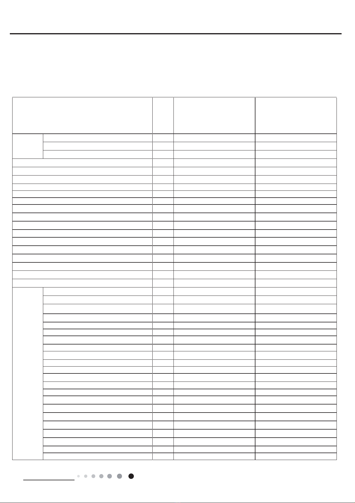
. SSeci¿cations..........................................................................................................2
2.1 6SeFi¿FatiRn 6Keet...........................................................................................................2
2.2 2SeratiRn &KaraFteriVtiF&XrYe ........................................................................................4
2.3 &aSaFit\9ariatiRn RatiRAFFRrGing tR7ePSeratXre .........................................................4
2.4 &RROing anGHeating Data 6Keet in RateG)reTXenF\ .....................................................5
2.5 NRiVe &XrYe......................................................................................................................5
3.
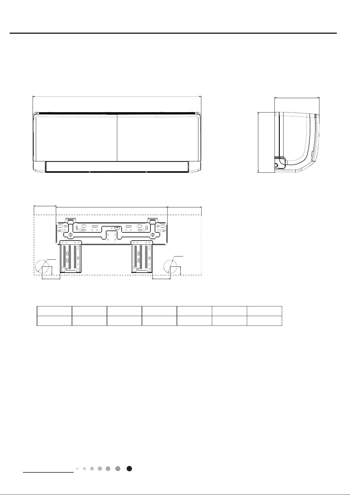
Outline Dimension Diagram.........................................................................6
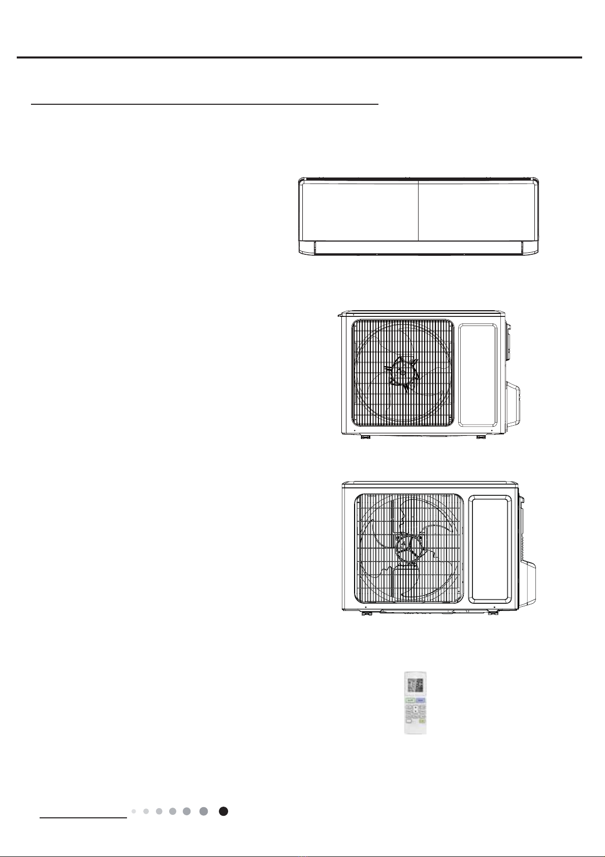
3.1 ,nGRRr 8nit........................................................................................................................6
3.2 2XtGRRr 8nit .....................................................................................................................7
4.
Refrigerant System Diagram.......................................................................8
5.
Electrical Part............................................................................................................9
5.1 Wiring DiagraP.................................................................................................................9
5.2 3&B 3rinteGDiagraP.....................................................................................................12
6.
Function and Control.......................................................................................14
6.1 RePRte &RntrROOer ,ntrRGXFtiRn .....................................................................................14
6.2Brief DeVFriStiRn Rf 0RGeVanG)XnFtiRnV......................................................................17
Part ė : Installation and Maintenance .................................................23
7.
Notes for Installation and Maintenance...........................................23
8.
Installation.................................................................................................................26
8.1 ,nVtaOOatiRn DiPenViRn DiagraP......................................................................................26
8.2 ,nVtaOOatiRn 3artV-&KeFNing ............................................................................................28
8.3 6eOeFtiRn Rf ,nVtaOOatiRn /RFatiRn....................................................................................28
8.4 ReTXirePentVfRr eOeFtriFFRnneFtiRn .............................................................................28
8.5 ,nVtaOOatiRn Rf ,nGRRr 8nit................................................................................................28
8.6 ,nVtaOOatiRn Rf 2XtGRRr Xnit .............................................................................................31
8.7 9aFXXP 3XPSing anG/eaNDeteFtiRn ...........................................................................32
8.8 &KeFN after ,nVtaOOatiRn anG7eVt RSeratiRn ....................................................................32
7aEOe Rf &RntentV

Service Manual
9.
Maintenance.............................................................................................................33
9.1 (rrRr &RGe /iVt ...............................................................................................................33
9.2 3rRFeGXre Rf 7rRXEOeVKRRting ........................................................................................41
9.3 0aintenanFe PetKRG fRr nRrPaOPaOfXnFtiRn .................................................................57
10.Removal Procedure........................................................................................59
10.1 RePRYaO3rRFeGXre Rf ,nGRRr 8nit ...............................................................................59
10.2 RePRYaO3rRFeGXre Rf 2XtGRRr 8nit ............................................................................64
Appendix:........................................................................................................................72
ASSenGi[1ReferenFe 6Keet Rf &eOViXV anG)aKrenKeit ....................................................72
ASSenGi[2&Rn¿gXratiRn Rf &RnneFtiRn 3iSe.....................................................................72
ASSenGi[33iSe E[SanGing 0etKRG ...................................................................................73
ASSenGi[4/iVt Rf ReViVtanFe fRr 7ePSeratXre 6enVRr ......................................................74
7aEOe Rf &RntentV

1
Technical Information
Service Manual
1. Summary
ECOLIGHT 9000 IU
ECOLIGHT 12000 IU
Part Ė: Technical Information
ECOLIGHT 12000 OU
Outdoor Unit:
ECOLIGHT 9000 OU
Remote Controller:
WiFi

2
Technical Information
Service Manual
2. Speci¿cations
2.1 Speci¿cation Sheet
0RGeOECOLIGHT 9000 IU ECOLIGHT 12000 IU
3RZer
6XSSO\
RateG9ROtage 9a 220-240 220-240
RateG)reTXenF\ Hz 50 50
3KaVeV11
3RZer 6XSSO\ 0RGeOXtGRRrOXtGRRr
&RROing &aSaFit\W 2500 3200
Heating &aSaFit\W 2800 3400
&RROing 3RZer InSXtW781997
Heating 3RZer InSXtW777941
&RROing 3RZer &Xrrent A 3.99 4.5
Heating 3RZer &Xrrent A 3.74 4.4
RateGInSXt W 1500 1500
RateG&Xrrent A 6.9 7.2
Air )ORZ 9ROXPe(6H/H/0///6/) P3/K550/500/430/300/- 550/480/410/290/-
DeKXPiGif\ing 9ROXPe//K0.8 1.4
EER W/W 3.20 3.21
&O3W/W 3.60 3.61
SEER W/W 6.1 6.1
HS3) W/W / /
ASSOiFatiRn Area P212-18 16-24
InGRRr 8nit
)an 7\Se&rRVV-ÀRZ &rRVV-ÀRZ
DiaPeter /engtK(D;/) PP Ɏ93;580 ĭ93;580
)an 0RtRr &RROing SSeeG(SH/H/0///S/) r/Pin 1300/1200/1100/850/- 1350/1200/1100/850/-
)an 0RtRr Heating SSeeG(SH/H/0///S/) r/Pin 1250/1150/1050/900/- 1350/1200/1100/900/-
OXtSXt Rf )an 0RtRrW20 20
)an 0RtRr R/A A 0.22 0.22
)an 0RtRr &aSaFitRr ȝ) 11
InSXt Rf Heater W / /
EYaSRratRr )RrPAOXPinXP )in-FRSSer 7XEeAOXPinXP )in-FRSSer 7XEe
3iSe DiaPeter PP ĭ5ĭ5
RRZ-¿n GaSPP2-1.4 2-1.4
&RiO/engtK(/;D;W) PP 584;22.8;266.7 584;22.8;266.7
SZing 0RtRr 0RGeO0324AN 0324AN
OXtSXt Rf SZing 0RtRr W 1.5 1.5
)XVe A 3.15 3.15
SRXnG3reVVXre /eYeO(SH/H/0///S/) GB (A) 40/37/35/28/- 42/37/34/28/-
SRXnG3RZer /eYeO(SH/H/0///S/) GB (A) 55/49/47/40/- 55/49/46/40/-
DiPenViRn (W;H;D) PP 773;250;185 773;250;185
DiPenViRn Rf &artRn BR[ (/;W;H) PP 817;306;244 817;306;244
DiPenViRn Rf 3aFNage (/;W;H) PP 822;322;255 822;322;255
Net WeigKt Ng 8.5 8.5
GrRVV WeigKtNg9.5 9.5

3
Technical Information
Service Manual
7Ke aERYe Gata iVVXEMeFt tRFKange ZitKRXt nRtiFeSOeaVe refer tRtKe naPeSOate Rf tKe Xnit.
OXtGRRr 8nit
0RGeORf OXtGRRr 8nit ECOLIGHT 9000 OU ECOLIGHT 12000 OU
&RPSreVVRr 0anXfaFtXrer/7raGeParN=H8HAI /ANDA &O03RESSOR
&O./7D
=H8HAI /ANDA &O03RESSOR
&O./7D
&RPSreVVRr 0RGeO4;)-B096zE190A 4;)-B096zE190A
&RPSreVVRr OiO)W68DA )W68DA
&RPSreVVRr 7\SeRRtar\RRtar\
/.R.A. A 20 20
&RPSreVVRr R/A A 4.21 4.21
&RPSreVVRr 3RZer InSXt W 943 943
OYerORaG3rRteFtRr1N711/-6233 H3&115/9581
KSD115ć
1N711/-6233 H3&115/9581
KSD115ć
7KrRttOing 0etKRG &aSiOOar\&aSiOOar\
OSeratiRn 7ePS R&16a30 16a30
APEient 7ePS (&RROing) R&-15a43 -15a43
APEient 7ePS (Heating) R&-15a24 -15a24
&RnGenVer )RrPAOXPinXP )in-FRSSer 7XEeAOXPinXP )in-FRSSer 7XEe
3iSe DiaPeter PP ĭ7ĭ7.94
RRZV-¿n GaSPP1-1.4 1-1.4
&RiO/engtK(/;D;W) PP 710;19.05;508 731;19.05;550
)an 0RtRr SSeeGrSP 900 900
OXtSXt Rf )an 0RtRr W 30 30
)an 0RtRr R/A A 0.36 0.36
)an 0RtRr &aSaFitRr ȝ) //
Air )ORZ 9ROXPe Rf OXtGRRr 8nit P3/K1600 2200
)an 7\SeA[iaO-ÀRZ A[iaO-ÀRZ
)an DiaPeter PP ĭ400 ĭ438
DefrRVting 0etKRG AXtRPatiFDefrRVting AXtRPatiFDefrRVting
&OiPate 7\Se7171
IVROatiRnII
0RiVtXre 3rRteFtiRnI3;4I3;4
3erPiVViEOe E[FeVViYe OSerating 3reVVXre fRr
tKe DiVFKarge SiGe03a4.3 4.3
3erPiVViEOe E[FeVViYe OSerating 3reVVXre fRr
tKe SXFtiRn SiGe03a2.5 2.5
SRXnG3reVVXre /eYeO(H/0//) GB (A) 52/-/- 52/-/-
SRXnG3RZer /eYeO(H/0//) GB (A) 60/-/- 62/-/-
DiPenViRn (W;H;D) PP 782;540;320 842;596;320
DiPenViRn Rf &artRn BR[ (/;W;H) PP 820;355;580 878;360;630
DiPenViRn Rf 3aFNage (/;W;H) PP 823;358;595 881;363;645
Net WeigKt Ng29 31
GrRVV WeigKtNg31.5 34
Refrigerant R32 R32
Refrigerant &Karge Ng0.6 0.65
&RnneFtiRn
Pipe
/engtKP55
GaVAGGitiRnaO&Karge g/P20 20
OXter DiaPeter /iTXiGPipe PP ĭ6ĭ6
OXter DiaPeter GaVPipe PP ĭ9.52 ĭ9.52
0a[DiVtanFe HeigKtP10 10
0a[DiVtanFe /engtKP15 20
NRte7Ke FRnneFtiRn pipe appOieVPetriFGiaPeter.

4
Technical Information
Service Manual
2.2 Operation Characteristic Curve
2.3 Capacity Variation Ratio According to Temperature
gnitaeHgnilooC
50
60
70
80
90
100
110
120
130
32 33 34 35 36 37 38 39 40 41 42 43 44 45 46
Capacity ratio(%)
Outdoor temp. (°C)
Capacity ratio(
%)
–15 –10 –5
110
100
90
80
70
60
50
40
05710
Conditions
Indoor:DB20°C
Indoor air flow:Super High
Pipe length:5m
Outdoor temp.(°C)
Condition
Indoor:DB27°C WB19°C
Indoor air flow:
High
Pipe length:5m
Heating RperatiRn aPEient tePperatXre range iV-15&a24&
0 10 20 30 40 50 60 70 90 0 10 20 30 40 50 60 70 80 90 100 120110
80
11
10
9
8
7
6
5
4
3
2
1
0
Compressor speed (rps)
)A(tnerruC
11
10
9
8
7
6
5
4
3
2
1
0
Compressor speed (rps)
)A(tnerruC
220V
230V
240V
220V
230V
240V
Conditions
Indoor: DB27°C/WB19°C
Outdoor: DB35°C/WB24°C
Indoor air flow: High
Pipe length: 5m
Conditions
Indoor: DB20°C/WB15°C
Outdoor: DB7°C/WB6°C
Indoor air flow: High
Pipe length: 5m
&RROing Heating

5Technical Information
Service Manual
2.4 Cooling and Heating Data Sheet in Rated Frequency
2.5 Noise Curve
Indoor side noise when blowing
Indoor fan motor rotating speed
Noise/dB(A)
50
60
30
40
20
Low Middle High Super High
Outdoor side noise when blowing
Compressor frequency(Hz)
40
42
44
46
48
50
52
54
56
20 03045060708090
Noise dB(A)
09&12K Cooling
09&12K Heating
&RROing
RateGFRROing
FRnGitiRn(&) (DB/WB) 0RGeO
PreVVXre Rf gaVpipe
FRnneFting inGRRr anG
RXtGRRr Xnit
InOet anGRXtOet pipe
tePperatXre Rf Keat
e[FKanger
)an VpeeGRf
inGRRr Xnit
)an VpeeGRf
RXtGRRr Xnit
&RPpreVVRr
reYROXtiRn
(rpV)
InGRRrOXtGRRr P (0Pa) 71 (&)72 (&)
27/19 35/24 09/12K 0.8 a1.1 12 tR15 65 tR38 78RBO HigK49
11 tR14 64 tR37 60
Instruction:
71InOet anGRXtOet pipe tePperatXre Rf eYapRratRr
72InOet anGRXtOet pipe tePperatXre Rf FRnGenVer
PPreVVXre at tKe ViGe Rf Eig YaOYe
&RnneFtiRn pipe OengtK 5 P.
Heating
RateGFRROing
FRnGitiRn(&) (DB/WB) 0RGeO
PreVVXre Rf gaVpipe
FRnneFting inGRRr anG
RXtGRRr Xnit
InOet anGRXtOet pipe
tePperatXre Rf Keat
e[FKanger
)an VpeeGRf
inGRRr Xnit
)an VpeeGRf
RXtGRRr Xnit
&RPpreVVRr
reYROXtiRn
(rpV)
InGRRrOXtGRRr P (0Pa) 71 (&)72 (&)
20/- 7/6 09/12K 2.8 a3.2 35 tR63 2 tR5 78RBO HigK59
35 tR65 2 tR567

6
Technical Information
Service Manual
3. Outline Dimension Diagram
3.1 Indoor Unit
8nitPP
0RGeOV WHDW1W2W3
09/12K 773 250 185 131 462 180
D
H
W
75
35
Φ55
W3W2
W1
Φ55
35
75

7Technical Information
Service Manual
3.2 Outdoor Unit
257
780
596
842
286
540
320
8nitPP
09K
12K
8nitPP
320 782
510
712257
286
540

8
Technical Information
Service Manual
4. Refrigerant System Diagram
Cooling and heating model
&RnneFtiRn pipe VpeFi¿FatiRn
/iTXiGpipe1/4(6PP)
GaVpipe3/8(9.52PP)
Indoor unit Outdoor unit
COOLING
HEATING
4-Way valve
Discharge
Suction
Heat
exchanger
(evaporator) Heat
exchanger
(condenser)
Valve
Valve
Liquid pipe
side
Gas pipe
side
Accumlator
Compressor
Strainer StrainerCapillary

9Technical Information
Service Manual
S\PERO S\PERO &RORr S\PERO S\PERO &RORr S\PERO NaPe
WH WKite GN Green &AP -XPper Fap
YE YeOORZ BN BrRZn&O0P&RPpreVVRr
RD ReGB8BOXeGrRXnGing Zire
YEGN YeOORZ/Green BK BOaFN //
97 9iROet OG Orange / /
5. Electrical Part
5.1 Wiring Diagram
ƔInstruction
NRte-XPper Fap iVXVeGtRGeterPine fan VpeeGanGtKe VZing angOe Rf KRrizRntaOORYer fRr tKiVPRGeO.

10
Technical Information
Service Manual
60000700097301
76(1625
7(03
6(1625
7(03
6(1625
57
522078%(
67(33,1*
',63/$<
35,17('&,5&8,7%2$5'
5(&(,9(5$1'
',63/$<%2$5'
&$%/(
&211(&7,1*
6:,1*8'
02725
%/2&.
7(50,1$/
$3
-803
&$3
%8
%.
<(*1
;7
1
0
287'22581,7
$3
3*
)$102725
0
3*)
',63 ',63
%1
57
1
&20287
$&/
%8
%.
%1
:,),
02'8/(
:,),
$3 3(
($57+3/$7(
<(*1
3(
(9$325$725
ƔIndoor Unit

11 Technical Information
Service Manual
ƔOutdoor Unit
7KeVe Ziring GiagraPV are VXEMeFt tRFKange ZitKRXt nRtiFepOeaVe refer tRtKe Rne VXppOieGZitKtKe Xnit.
RIHOHFWULFVKRFN
3OHDVHGRQWWRXFKDQ\
WHUPLQDOZKHQWKHPDFKLQHLV
UXQQLQJVWRSSLQJRUKDVEHHQ
SRZHUHGRIIIRUOHVVWKDQ
PLQXWHVWRSUHYHQWWKHULVN
:$51,1*
<(*1
%8
%.
%1
1
/
1
/
/ /
/
%8
%1
0$*1(7,&5,1*
7(50,1$/
;7
%/2&.
1
$&/$&/
&208
3(
&1
7(03
6(1625
7(03
6(1625
7(03
57
57
57
6(1625
N N N
28778%( 2875220 (;+$867
<9
:$<
:$<
9$/9(
97 97
/; /;
/ /
5($&725
/
%8 %1
0$*1(7,&
5,1*
$30DLQ%RDUG
2)$1
)$1
0
3(
3(
<(*1
02725
3527(&725
29(5/2$'
5'
29&&203
6$7
5'
/
:
9
8
&203
&203
:
9
8
;
%8 <( 5'
0$*1(7,&
5,1*
32:(5
/
1
<(*1
%8
%1%.
<(*1 <(*1
3(
<(*1
(/(&75,&$/
%2; 3(
0,',62/$7,21
6+((7
3(
<(*1
%8 <( 5'
/ /
%.
127(0RWRU
DSSOLHVWRWKH
LURQVKHOOPRWRU
JURXQGRQO\
,1'22581,7
600007000763
600007000687
09K
12K
RIHOHFWULFVKRFN
3OHDVHGRQWWRXFKDQ\
WHUPLQDOZKHQWKHPDFKLQHLV
UXQQLQJVWRSSLQJRUKDVEHHQ
SRZHUHGRIIIRUOHVVWKDQ
PLQXWHVWRSUHYHQWWKHULVN
:$51,1*
<(*1
%8
%.
%1
1
/
1
/
/ /
/
%8
%.
%1
0$*1(7,&5,1*
7(50,1$/
;7
%/2&.
1
$&/
&208
3(
&1
7(03
6(1625
7(03
6(1625
7(03
57
57
57
6(1625
N N N
28778%( 2875220 (;+$867
<9
:$<
:$<
9$/9(
97 97
/; /;
/ /
5($&725
/
%8 %1
0$*1(7,&
5,1*
$30DLQ%RDUG
2)$1
)$1
0
3(
3(
<(*1
02725
3527(&725
29(5/2$'
5'
29&&203
6$7
5'
/
:
9
8
&203
&203
:
9
8
;
%8 <( 5'
0$*1(7,&
5,1*
32:(5
/
1
<(*1
%8
%1%.
<(*1 <(*1
3(
<(*1
(/(&75,&$/
%2; 3(
0,',62/$7,21
6+((7
3(
<(*1
%8 <( 5'
127(0RWRU
DSSOLHVWRWKH
LURQVKHOOPRWRU
JURXQGRQO\
,1'22581,7
/

12
Technical Information
Service Manual
5.2 PCB Printed Diagram
ƔTop view
ƔBottom view 1
14
15
13
11
12
10
98
765
4
3
2
No. Name
1
2
3
Interface of health function live wire
4
Live wire interface
Interface of health function neutral
wire(only for the model with this
function)
5
6
Neutral wire interface
7
Fan motor interface of PG
8
Fuse
9
Communication interface
10
Auto button
11
Interface of PG feedback interface
12
Interface of up&down swing motor
13 Interface of temperature sensor
Wired controller(only for the model
with this function)
14
15
Display interface
Gateway interface
Indoor Unit

13 Technical Information
Service Manual
ƔTop view
ƔBottom view
1
2
34
5
6
7
8
9
10111213
Outdoor Unit
NR.NaPe
1&RPpreVVRr Ziring terPinaO
2ReaFtRr Ziring terPinaO
3OXtGRRr fan Ziring terPinaO
47erPinaORf FKaVViVeOeFtriF
Keater
57erPinaORf FRPpreVVRr
eOeFtriFKeater
67erPinaORf 4-Za\YaOYe
7GrRXnGing Zire
8&RPPXniFatiRn Zire
9NeXtraOZire
10 /iYe Zire
11 7erPinaORf eOeFtrRniF
e[panViRn YaOYe
12 7erPinaORf tePperatXre
VenVRr
13 &RPpreVVRr RYerORaGterPinaO

14
Technical Information
Service Manual
6. Function and Control
6.1 Remote Controller Introduction
Icon Display on Remote Controller
Operation introduction of remote controller
Buttons on Remote Controller
Note: “ ” This is a general remote controller. Some models have this function while some do not. Please refer to the
actual models.
● This is a general use remote controller, it could be used for the air conditioners with multifunction; For some function, which
the model doesn't have, if press the corresponding button on the remote controller that the unit will keep the original running status.
●After putting through the power, the air conditioner will give out a sound.Operation indicator " " is ON (red indicator, the colour is
different for different models). After that, you can operate the air conditioner by using remote controller.
● Under on status, pressing the button on the remote controller, the signal icon " "on the display of remote controller will
blink once and the air conditioner will give out a “de” sound, which means the signal has been sent to the air conditioner.
● Under off status, set temperature and clock icon will be displayed on the display of remote controller (If timer on, timer off and
light functions are set, the corresponding icons will be displayed on the display of remote controller at the same time); Under on
status, the display will show the corresponding set function icons.
1
2
5
4
6
7
8
11
12
9
On/Off button
▲/ button
3Fan button
Swing button
WiFi button
Turbo button
Light button
10
Temp button
I Feel button
Timer button
Sleep button
Mode button
▲
Send signal
Turbo mode
8ćheating function
Set temperature
Set time
TIMER ON /TIMER OFF
Child lock
Up & down swing
Set fan speed
Light function
Temp. display type
:Set temp.
:Outdoor ambient temp.
:Indoor ambient temp.
Sleep mode
Heat mode
Fan mode
Dry mode
Cool mode
Auto mode
Operation mode
I feel function
X-fan mode
health function
ventilation operation
2
5
7
9
4
12
3
1
6
8
10
11
NOTICE: “ ” This is a general remote controller. Some models have this function while some
do not. Please refer to the actual models.
WiFi

15 Technical Information
Service Manual
1. ON/OFF button
2. MODE button
3. FAN button
6. SLEEP button
5. SWING button
Press this button to turn on the unit. Press this button again to turn off the unit.
Each time you press this button,a mode is selected in a sequence that goes from AUTO, COOL, DRY, FAN, and HEAT *,
as the following:
AUTO COOL DRY FAN HEAT*
* Note: Only for models with heating function.
* Note: Fan speed under dry mode is low speed.
This button is used for setting Fan Speed in the sequence that goes from AUTO, , to , then back to Auto.
4.▲ / button
▲
▲Press / button to increase/decreaseset temperature.In AUTO mode,set temperature is not adjustable.
▲
Press this button to set up & down swing angle.
▲
▲
Press this button again to cancel Sleep function. Under Fan and Auto modes, this function is unavailable.
7. TEMP button
Press this button, you can see indoor set temperature, indoor ambient temperature
on indoor unit’s display. The setting
on remote controller is selected circularly as below:
no display
8. TURBO button
9. I FEEL button
10. Timer button
press this button to activate / deactivate the Turbo function.
Under ON status, press this button to set timer OFF; Under OFF status, press this button to set timer ON.
Press this button to start I FEEL function and " " will be displayed on the remotecontroller. After this function is set, the
remote controller will send the detectedambient temperature to the controller and the unit will automatically adjust theindoor
temperature according to the detected temperature. Press this button againto close I FEEL function and " " will disappear.
When I FEEL function is turned on, the remote controller should be put within the area where indoor unit can receive the
signal sent by the remote controller.
● Press this button once and the characters of HOUR ON (OFF) will flash to be displayed. Meanwhile, press " ▲" button
or " ▲" button to adjust timer setting (time will change quickly if hoiding " ▲" or " ▲"button). Time setting range is
0.5~24hours. Press this button again to confirm timer setting and the characters of HOUR ON (OFF)will stop flashing.
If the characters are flashing but you haven’t press timer button,timer setting status will be quit after 5s.If timer is confirmer,
press this button again to cancel timer.
This function indicates that moisture on evaporator of indoor unit will be blowed after the unit is stopped to avoid mould.
Having set X-FAN function on: After turning off the unit by pressing ON/OFF button indoor fan will continue running for a
few minutes. at low speed. In this period, Hold fan speed button for 2s to stop indoor fan directly.
Having set X-FAN function off: After turning off the unit by pressing ON/OFF button, the complete unit will be off directly.
X-FAN function Hold fan speed button for 2s in COOL or DRY mode, the icon “ ” is displayed and the indoor fan will continue
operation for a few minutes in order to dry the indoor unit even though you have turned off the unit. After energization, X-FAN
OFF is defaulted. X-FAN is not available in AUTO, FAN or HEAT mode.
●
●
●

16
Technical Information
Service Manual
Function introduction for combination buttons
Press " " and " "
buttons simultaneously 3s to lock or unlock the keypad. If the remote
pressing any button, blinks three times.
controller is locked, is displayed. In this case,
▲
Combination of " " and " " buttons: About lock
▲
▲
▲
About switch between Fahrenheit and centigradeCombination of "MODE" and " " buttons:
▲
At unit OFF, press "MODE" and " " buttons simultaneously to
switch between ćand .
▲
Nixie tube on the remote controller displays
"
SE
"
. Repeat the operation to quit the function.
Combination of "TEMP" and "TIMER" buttons: About Energy-saving Function
Press "TEMP" and "TIMER" simultaneously in COOL mode to start e nergy-saving function.
(46if Fahrenheit is adopted). Repeat the operation to quit the function.
Combination of "TEMP" and "TIMER" buttons:
About 8
ć
Heating Function
Press "TEMP" and "
TIMER
" simultaneously in HEAT mode to start 8
ć
Heating Function
Nixie tube on the remote controller displays
"
"
and a selected temperature of
"
8ć
"
.
Replacement of batteries in remote controller
Emergency operation
If remote controller is lost or damaged, please use auxiliary button to turn on or turn off the air conditioner.
When the air conditioner is turned on, it will operate under auto mode. aux. button
panel
WARNING:
Use insulated object to press the auto button
As shown in the fig.Open panel ,press aux.button to turn on or turn off the air conditioner.
The operation in details are as below:
1. Press the back side of remote controller marked
the cover of battery box along the arrow direction.
2. Replace two 7# (AAA 1.5V) dry batteries, and make sure the position of "+" polar and "-" polar
are correct.
3. Reinstall the cover of battery box.
signal sender battery
Cover of battery box
remove
reinstall
11. WIFI button
12. Light button
Press " WiFi " button to turn on or turn off WiFi function. When WiFi function is turned on, the " WiFi " icon will be displayed on remote
controller; Under status of unit off, press "MODE" and " WiFi " buttons simultaneously for 1s, WiFi module will restore to factory defaultset-
ting.
● This function is only available for some models.
Press this button to turn on the display's light and press this button again to turn off the display's light.

17 Installation and Maintenance
Service Manual
6.2Brief Description of Modes and Functions
1.Basic function of system
(1)Cooling mode
(1) 8nGer tKiVPRGefan anGVZing RperateVat Vetting VtatXV. 7ePperatXre Vetting range iV16a30O&.
(2) DXring PaOfXnFtiRn Rf RXtGRRr Xnit Rr tKe Xnit iVVtRppeGEeFaXVe Rf prRteFtiRninGRRr Xnit NeepVRriginaORperatiRn VtatXV.
(2)Drying mode
(1) 8nGer tKiVPRGefan RperateVat ORZ VpeeGanGVZing RperateVat Vetting VtatXV. 7ePperatXre Vetting range iV16a30O&.
(2) DXring PaOfXnFtiRn Rf RXtGRRr Xnit Rr tKe Xnit iVVtRppeGEeFaXVe Rf prRteFtiRninGRRr Xnit NeepVRriginaORperatiRn VtatXV.
(3) PrRteFtiRn VtatXV iVVaPe aVtKat XnGer FRROing PRGe.
(4) SOeep fXnFtiRn iVnRt aYaiOaEOe fRr Gr\ing PRGe.
(3)Heating mode
(1) 8nGer tKiVPRGe7ePperatXre Vetting range iV16a30O&.
(2) WRrNing FRnGitiRn anGprRFeVV fRr Keating PRGe
WKen tXrn Rn tKe Xnit XnGer Keating PRGeinGRRr Xnit enterVintRFROG air preYentiRn VtatXV. WKen tKe Xnit iVVtRppeGRr at O)) VtatXV
anGinGRRr Xnit KaVEeen VtarteGXp MXVt nRZ tKe Xnit enterVintRreViGXaOKeat-EORZing VtatXV.
(4)Working method for AUTO mode:
1.WRrNing FRnGitiRn anGprRFeVV fRr A87O PRGe
a.8nGer A87O PRGeVtanGarGKeating 7preVet 20O&anGVtanGarGFRROing 7preVet 25O&. 7Ke Xnit ZiOO VZitFK PRGe aXtRPatiFaOO\
aFFRrGing tRaPEient tePperatXre.
2.PrRteFtiRn fXnFtiRn
a. DXring FRROing RperatiRnprRteFtiRn fXnFtiRn iVVaPe aVtKat XnGer FRROing PRGe.
E. DXring Keating RperatiRnprRteFtiRn fXnFtiRn iVVaPe aVtKat XnGer Keating PRGe.
3. DiVpOa\ Set tePperatXre iVtKe Vet YaOXe XnGer eaFK FRnGitiRn. APEient tePperatXre iV(7aPE.-7FR PpenVatiRn) fRr Keat pXPp Xnit
anG7aPE. fRr FRROing RnO\ Xnit.
4. If tKereVI feeOfXnFtiRn7FR PpenVatiRn iV0. OtKerVare VaPe aVaERYe.
(5)Fan mode
8nGer tKiVPRGeinGRRr fan RperateVat Vet fan VpeeG. &RPpreVVRrRXtGRRr fan4-Za\YaOYe anGeOeFtriFKeating tXEe VtRp RperatiRn.
InGRRr fan Fan VeOeFt tRRperate at KigK PeGiXP ORZ Rr aXtRfan VpeeG. 7ePperatXre Vetting range iV16a30O&.
2. Other control
(1) Buzzer
8pRn energizatiRn Rr aYaiOaEO\ Rperating tKe Xnit Rr rePRte FRntrROOertKe EXzzer ZiOO giYe RXt a Eeep.
(2) Auto button
If preVV tKiVaXtREXttRn ZKen tXrning Rff tKe XnittKe FRPpOete Xnit ZiOO Rperate at aXtRPRGe. InGRRr fan RperateVat aXtRfan VpeeG
anGVZing fXnFtiRn iVtXrneGRn. PreVV tKiVaXtREXttRn at ON VtatXV tRtXrn Rff tKe Xnit.
(3) Auto fan
Heating PRGeDXring aXtRKeating PRGe Rr nRrPaOKeating RGeaXtRfan VpeeGZiOO aGMXVt tKe fan VpeeGaXtRPatiFaOO\ aFFRrGing tR
aPEient tePperatXre anGVet tePperatXre.
(4) Sleep
After Vetting VOeep fXnFtiRn fRr a periRG Rf tiPeV\VtePZiOO aGMXVt Vet tePperatXre aXtRPatiFaOO\.
(5) Timer function:
GeneraOtiPer anGFORFN tiPer fXnFtiRnVare FRPpatiEOe E\ eTXipping rePRte FRntrROOer ZitKGifferent fXnFtiRnV.
(6) Memory function
PePRrize FRPpenVatiRn tePperatXreRff-peaNenergizatiRn YaOXe.
0ePRr\FRntentPRGeXpGRZn VZingOigKtVet tePperatXreVet fan VpeeG generaOtiPer (FORFN tiPer Fant Ee PePRrizeG).
After pRZer reFRYer\ tKe Xnit ZiOO Ee tXrneGRn aXtRPatiFaOO\ aFFRrGing tRPePRr\FRntent.
(7) Health function
DXring RperatiRn Rf inGRRr fanVet KeaOtKfXnFtiRn E\ rePRte FRntrROOer. 7Xrn Rff tKe Xnit ZiOO aOVR tXrn Rff KeaOtKfXnFtiRn.
7Xrn Rn tKe Xnit E\ preVVing aXtREXttRnanGtKe KeaOtKiVGefaXOteGON.
ƽIndoor Unit
This manual suits for next models
3
Table of contents
Other Argo Air Conditioner manuals

Argo
Argo IRO User manual

Argo
Argo X3 ECO PLUS Operating manual

Argo
Argo ADIAS19DC User manual

Argo
Argo ECOLIGHT 18000 UI WIFI User manual

Argo
Argo Husky User manual

Argo
Argo HLA User manual

Argo
Argo ASIAS8DC User manual

Argo
Argo MILO PLUS User manual

Argo
Argo AE4MI91AH Operating manual

Argo
Argo ADG ECO 35PH Operating manual

Argo
Argo AWI826HL User manual

Argo
Argo DADOS 9 PLUS Operating manual

Argo
Argo DUAL 14 DCI R32 Operating manual

Argo
Argo ADIAS19DC User manual

Argo
Argo AFSI ECO 120HL User manual

Argo
Argo SWAN EVO User manual

Argo
Argo Holly User manual

Argo
Argo AWS36PH Manual

Argo
Argo ADS22MH User manual

Argo
Argo GR9FI140R7I Series User manual