7
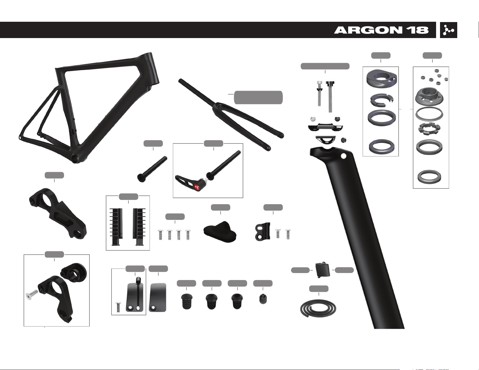
3. Frameset Parts, SKUs and descriptions
No. Name Assembled on A18 SKU# Qty
Parts already assembled
Parts
1 Nitrogen Disc Frame - - 1
2 Nitrogen Disc Fork - FK.NITD.340A 1
FK.NITD.340B
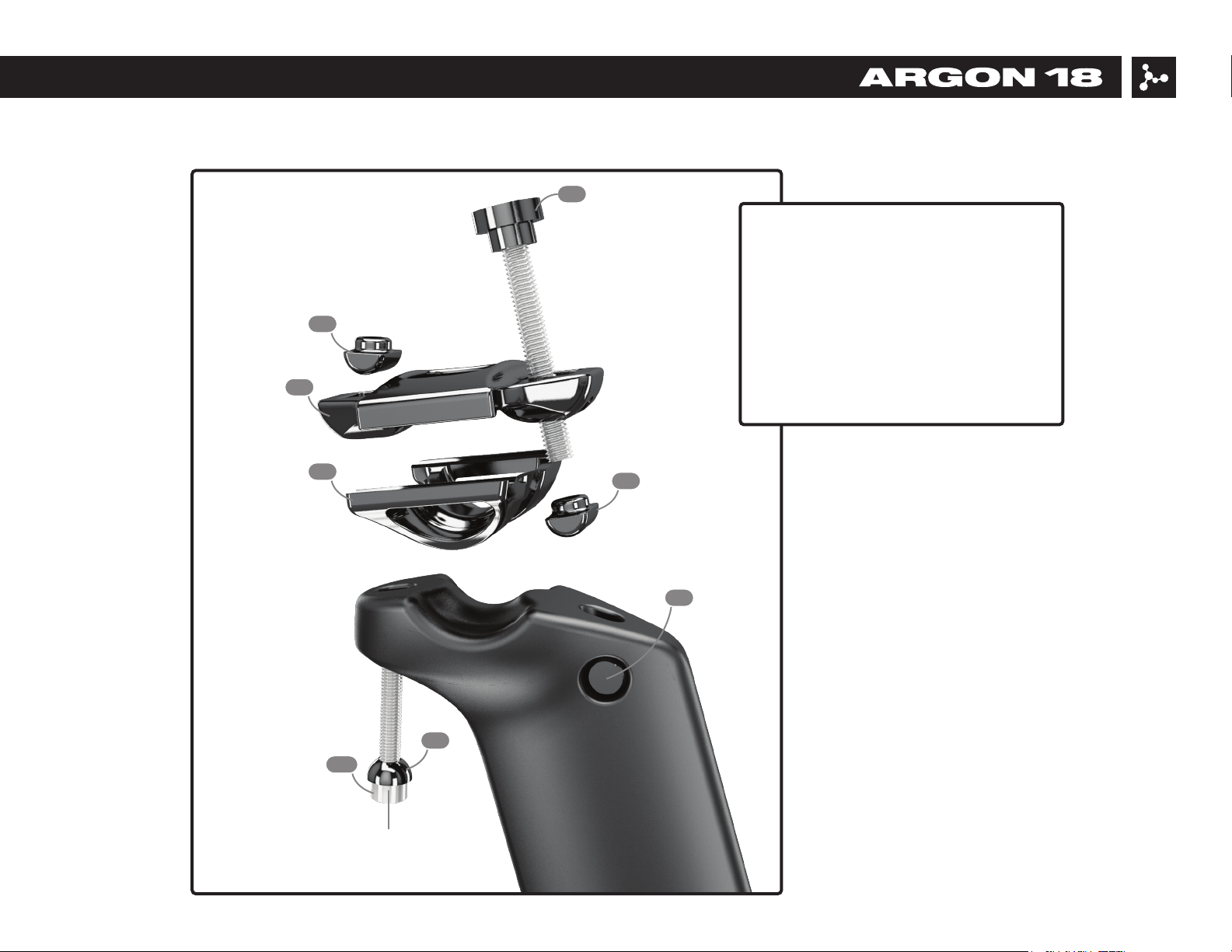
3 Nitrogen Disc Seat Post Assembly - SP.NIT_D.286A 1
10 BB Cover (incl. screw) Frame 38260 1
11 Seat Clamp Base (incl. screw) Frame 80478 1
12 Seat Clamp Wedge (incl. screw) Frame 80477 1
13 Di2 Cable Grommet Frame 38888 1
16 Headset (Token or FSA ACR) Fork Token: 81300 / FSA: 81299 1
20 Internal Di2 Battery Support Seat Post 38757 1 Set
24 Direct Mount Rear Derailleur Hanger Frame 80832 1
25 DT Swiss RWS Thru-axle FRONT 12 x 119mm Fork 80812 1
26 DT Swiss RWS Thru-axle REAR 12 x 161mm with handle Frame 80813 1
28 Oblong Cable Guide Frame 80551 1
32 Foam liner for housing Frame 80811 2
33 LONG GROMMET MECH frame 80985 1
34 Long plug frame 80804 1
35 Long Grommet DI2 frame 80805 1
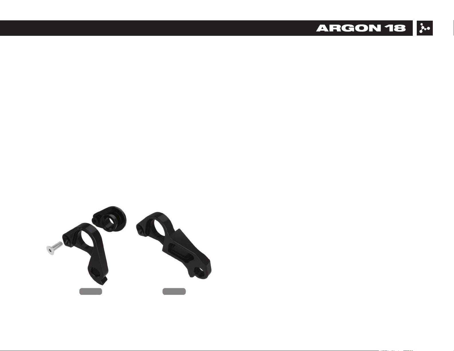
8 Rear Derailleur Hanger (incl. dropout, screw) Frame 80802 1
6 Front Derailleur Hanger (incl. screws) Frame 38882 1
9 BB Cable Guide (incl. screw) Frame 38885 1
7 Bottle Cage Screws Frame 38884 4
*Except for the frame itself, which is not sold as a spare part, all parts can be ordered by referring to their respective SKU number.