100 Clark Street, St. Charles, Missouri 63301
AMERICAN RAILCAR INDUSTRIES, INC.
636.940.6020
•
FAX: 636.940.6100
www.americanrailcar.com
•
sales@americanrailcar.com
02/2010
Valve Leak Testing
1. Safety Relief Valve leak tests must be conducted in accordance with AAR M-1002, Section C-III,
Appendix T. The inspector must be Level I qualified or higher.
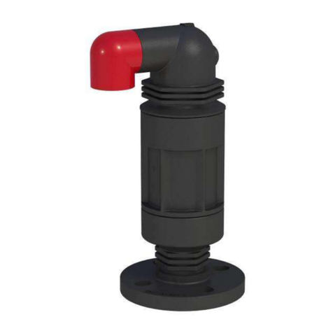
2. Apply the safety valve to the test stand.
3. Cycle the valve by applying shop air or nitrogen to the stand.
4. Plug the valve body drain opening using putty or a foam ear plug. Fill the cavity to the top of the
O-ring retainer.
5. Increase air pressure under the valve until the valve opens or “pops.”
6. Reduce pressure until the valve is closed and there are no bubbles present.
7. Refill the chamber and begin slowly increasing pressure under the valve until the first bubble
appears. This is the start-to-discharge pressure (STD) and must be within the tolerances provided
in the previous section, Guidelines for Testing and Adjustment.
8. If the start-to-discharge pressure falls outside the specified range, adjust the valve spring by
tightening the adjustment nut to increase the discharge pressure and loosen to decrease. Repeat
Steps 4-6.
9. NOTE: If adjusting the spring tension produces the opposite of the desired effect, the spring
could be defective and must be replaced.
10. Once the proper start-to-discharge pressure is attained, slowly decrease the pressure until the
bubbles stop. This is the vapor-tight pressure and must be within the tolerances provided in the
previous section, Guidelines for Testing and Adjustment.
11. A vapor-tight pressure falling below the specified minimum could indicate a problem with the
O-rings not sealing properly. Release all pressure from under the valve and remove the O-ring
Retainer following the instructions under section, Disassembly of the Top Guide and O-ring
Retainer, steps 2-6. Visually inspect the O-rings for nicks, gouges or improper setting in the
retainer. Visually inspect the seating surface. A finger nail run across the surface can pick up
discontinuities that are not readily visible. Any defect must be corrected.
12. Once the start-to-discharge and vapor-tight pressures are attained, test a second time to confirm
the settings then tighten the stem locknut and install the seal wires per steps 10 & 11 in the
Assembly Procedure section.
13. Mark the valve per AAR M-1002, Section C-III, Appendix A, Paragraph 7.1.2.
The undertaking of repair or replacement by the Purchaser, or its agents, without the expressed written consent of American
Railcar Industries, Inc. (ARI) shall void ARI’s warranty and relieve ARI of all responsibility. Under no circumstances shall ARI
be liable for any direct, incidental, consequential or other damages of any kind in connection with the installation, operation,
maintenance, repair, inspection or other use of any product purchased from it.
