manuals.online logo
Brands
  1. Home
  2. •
  3. Brands
  4. •
  5. Jaycar
  6. •
  7. Control Unit
  8. •
  9. Jaycar Maycar Electronic Dice Kit User manual

Jaycar Maycar Electronic Dice Kit User manual

learn to solder: Electronic Dice Kit Cat no. KM1099 1
Thank you for purchasing the Electronic Dice Kit
Take your soldering skills to the next level with this Electronic
Dice Kit.
Once built, you simply shake the module to generate a
random number between one a six, indicated by the LEDs
on the top!
Powered by a CR2032 battery (not included).
If this is the rst time you are getting into electronics and
handling a soldering iron, please download our Soldering
Guide from our website.
learn to solder:
Electronic
Dice Kit
Build Instructions &
Soldering Guide available at:
www.jaycar.com.au/p/KM1099
Disclaimer: Content can change without prior notice. Please visit the website page for the most up-to-date information.
A GOOD SOLDER JOINT
The diagram here shows you a good solder joint and two
bad solder joints. A good solder joint is clean and shiny with
a “volcano” shape, which means the component’s leg is fully
soldered to the entire solder pad on the circuit board. If your
solder joint is like the one shown in the middle, it means
you have not applied enough heat to the solder pad on the
circuit board. If your solder joint looks like the one on the
right, it means the component leg was not heated enough
by your soldering iron for the solder to join properly.
RECOMMENDED TOOLS. You will need the usual Maker essentials, including a soldering iron (TS1652 Soldering Iron Kit),
solder (NS3010), and side cutters (TH1897). A third-hand PCB holder (TH1987) is also recommended to make soldering easier.
GOOD
Shiny “Volcano”
type shape
BAD
The solder pad is
too cold
BAD
Component leg
too cold
learn to solder: Electronic Dice Kit Cat no. KM1099 2
Solder components onto the top and
bottom circuit boards, then x together
with the included spacers and screws.
Pay close attention to the way some of
these components go in because some
of them only work in one direction,
including the LEDs.
INTEGRATED CIRCUIT (IC). Instead of
soldering the IC into the circuit board
we have supplied an IC socket. Solder
the IC socket into the circuit board,
then insert the IC into that socket once
all of the other soldering is complete.
Make sure the IC is inserted with the
notch in the end matching the diagram
printed on the circuit board.
ELECTROLYTIC CAPACITOR. This capacitor
(C2) needs to be inserted into the circuit
board with the longer leg going into the
circuit board marked with the + symbol.
RESISTORS. Resistors can go into the
circuit board in either direction.
The colour bands indicate the resistor
value (See parts list for the colour
bands). Make sure you insert the correct
ones into the circuit board.
MONOLYTHIC CAPACITOR.
This capacitor (C1) can be
soldered in either way.
FINAL STEP. Solder in the switch
(S1) and the battery holder (E1).
Insert a CR2032 battery and then
tightly screw the two boards
together using the supplied spacers
and screws. These need to be
tight to make electrical connection
between the two boards. Shake and
the Dice should work.
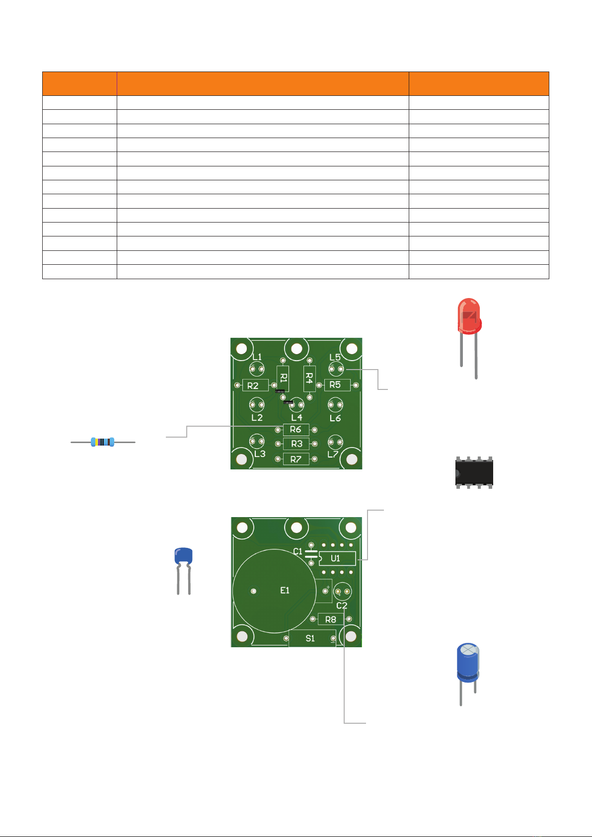
TOP BOARD
BOTTOM BOARD
QTY PRODUCT PCB MARKING / COMMENT
1Circuit Board Top L1-L7 markings is the top board
1 Circuit Board Bottom E1 marking is the bottom board
11MΩ Resistor (Brown-Black-Green-Gold) R8
7560Ω Resistor (Green-Blue-Brown-Gold) R1 - R7
7 Red LEDs L1 to L7
1 12F508-I/P IC U1 ( Align with the notch )
1 IC Socket For the 12F508-I/P IC
1 10µF 50V Electrolytic Capacitor C2
1 0.1µF Monolythic Capacitor C1
10 M3 x 6mm Screws For spacing the two PCBs
5 M3 x 20mm Metal Spacers For spacing the two PCBs
1 CR2032 Battery Holder E1
1 Tilt Switch (SW-200D) S1
Kit contents:
LEDs. The short leg of the LED is the
negative (-) leg. These need to go into
the circuit board marked with the -
symbol.
Cathode (-)
(Flat Edge)
Anode (+)
(+) (-)

This manual suits for next models

1

Other Jaycar Control Unit manuals

Jaycar Maycar Robot Badge Kit User manual

Jaycar

Jaycar Maycar Robot Badge Kit User manual

Jaycar Duinotech Build A Christmas Tree Instructions for use

Jaycar

Jaycar Duinotech Build A Christmas Tree Instructions for use

Jaycar Maycar Owl Badge Kit User manual

Jaycar

Jaycar Maycar Owl Badge Kit User manual

Popular Control Unit manuals by other brands

Shini SPV-U Series manual

Shini

Shini SPV-U Series manual

Telit Wireless Solutions WL865E4-P user guide

Telit Wireless Solutions

Telit Wireless Solutions WL865E4-P user guide

Nexans XPLORER 144 - 3X48 Notice Instructions

Nexans

Nexans XPLORER 144 - 3X48 Notice Instructions

Broadcom CVPM02 Getting started guide

Broadcom

Broadcom CVPM02 Getting started guide

Alpha Outback Energy Cordex 24-400W manual

Alpha Outback Energy

Alpha Outback Energy Cordex 24-400W manual

Grundfos CU 241 Installation and operating instructions

Grundfos

Grundfos CU 241 Installation and operating instructions

Honeywell ADEMCO 4204 installation instructions

Honeywell

Honeywell ADEMCO 4204 installation instructions

SINAMICS SM120 user guide

SINAMICS

SINAMICS SM120 user guide

EKE-Electronics EKE-Trainnet AIM2505A Technical manual

EKE-Electronics

EKE-Electronics EKE-Trainnet AIM2505A Technical manual

Yoshitake SCV-3 product manual

Yoshitake

Yoshitake SCV-3 product manual

Eurotec MF52 Operation manual

Eurotec

Eurotec MF52 Operation manual

Viessmann Vitotronic 300 GW6B installation instructions

Viessmann

Viessmann Vitotronic 300 GW6B installation instructions

Bpt VLS/3 manual

Bpt

Bpt VLS/3 manual

Monacor ATT-306PEU instructions

Monacor

Monacor ATT-306PEU instructions

Comelit K1406 Technical manual

Comelit

Comelit K1406 Technical manual

Ingersoll-Rand X8I Operator's manual

Ingersoll-Rand

Ingersoll-Rand X8I Operator's manual

Cree XB-D Series manual

Cree

Cree XB-D Series manual

Philips CM-150 CA manual

Philips

Philips CM-150 CA manual

manuals.online logo
manuals.online logoBrands
  • About & Mission
  • Contact us
  • Privacy Policy
  • Terms and Conditions

Copyright 2025 Manuals.Online. All Rights Reserved.