SERVICE *
*Service of this machine should be performed by qualified personnel only.
Should questions arise, please contact Controlled Dehumidification at the number on the
front of this manual.
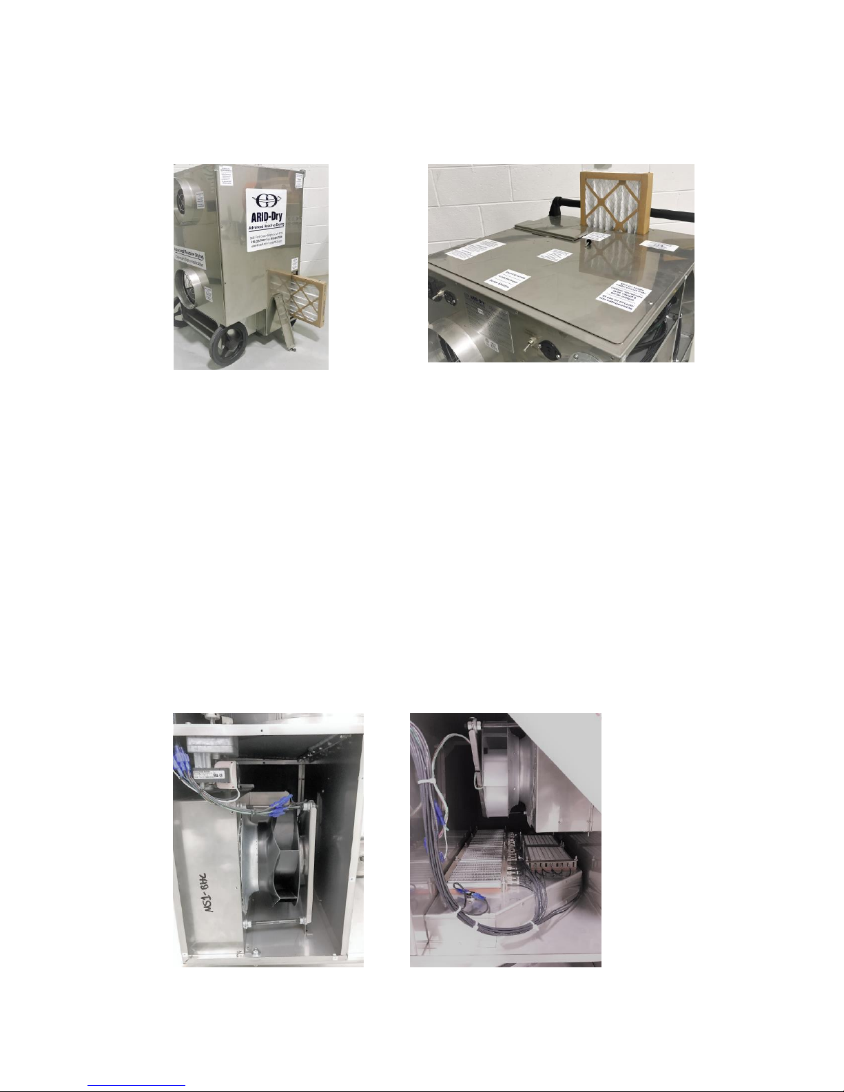
This machine is equipped with full perimeter service covers on both sides of the machine
for easy access for inspection, maintenance and service.
Note:
The process filter access cover must be removed prior to removing the service access
cover.
Process and React Fan Replacement
Disconnect power to the machine
Disconnect the fan wire spade terminals and remove the 3 hex nuts attaching the
motor/motor plate to the support studs.
Slide the assembly out of the machine.
Remove the fan from the mounting plate and install the new fan onto it.
Reverse removal procedure for installation.
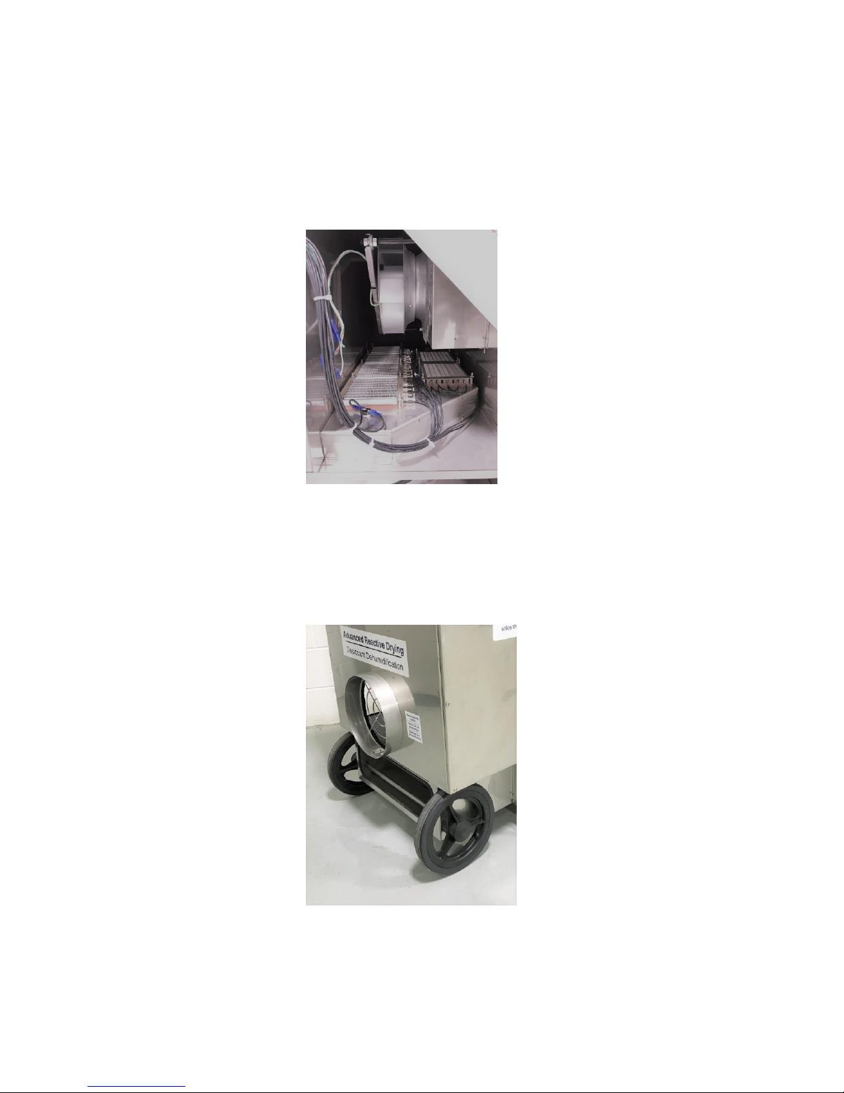
Rotor Replacement
Disconnect power from the machine.
Remove the drive belt from the tensioner roller to slack it.
Remove the two ¼-20 machine screws from the center of dividing panels at each face of
the rotor.
Carefully slide the rotor from the machine, using the belt to pull it.
The rotor shaft and top and bottom spacers will be loose.
Remove them as soon as they clear the dividing panels. They will be re-used.
Remove seal/drive bands from the perimeter of the rotor. They will be re-used.
Perimeter Seal Replacement
Verify length of new seals by wrapping around rotor, allowing for 1” of overlap.
Trim the ends of one edge of the seal with a small radius, overlap by 1-1/4” and staple
overlap in two places.
Prepare a second seal with the overlap opposite direction of the first.
Install new seals loosely on the rotor, overlap tabs pointing in direction of rotation, flush
with the face so they do not protrude.
Install the seal/drive bands around the rotor, on top of the seal, fingers pointing toward
each other.
Tighten the clamping screws so that the bands are snug, but not tight.
Install rotor, shaft and spacers with the rotor positioned so that the gap between the rotor
and rotor panel are even all the way around.
Tighten the cap screws securing the rotor shaft to the dividing panel.
Press the perimeter seals and drive bands toward the rotor panels, working around the
perimeter until the seals are uniformly cured toward the panels, approximately ½” of the
seal/clamp on the rotor.
Apply a bead of Silicone RTV to the joint where the inner edge of the seal, band, and
rotor perimeter band meet. Allow to cure prior to placing the rotor in service.
7