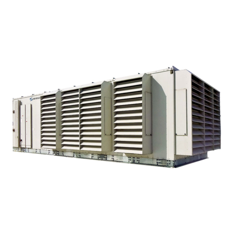
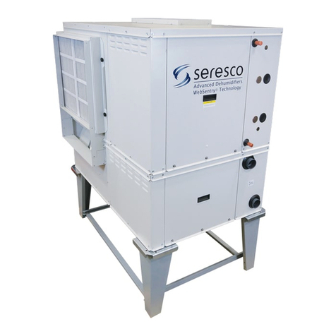
Seresco NP Series User manual

OPERATION AND
MAINTENANCE MANUAL
NP-018 to NE-128
Indoor/Outdoor Model
NP SERIES
DEHUMIDIFIERS
serescodehumidifiers.com

B–TableofContent
OMM.B.S.AA.01
B‐
1
February
2020
TableofContent
ChapterC‐GeneralInformation C–1
OperatingSafety
C–1
ReferenceandAdditionalInformation
C–2
o
ContactUs
C–2
BasicInformation
C–3
oDehumidifierViewandOptions
C–3
o
DehumidifierExternalSystemsConnection
C–5
oDehumidifierOptionalArrangement
C–5
oAirConditioningOptions–OutdoorAirFluidCoolers
C–6
o
EquipmentSpecificData
C–8
ChapterD‐LayoutandComponents D–1
DehumidifierMainComponents
D–1
ControlSystem
D–4
OutdoorAirFluidCoolerLayoutandComponents
D–5
ChapterE‐SequenceofOperation E–1
SetPoints
E–1
Ventilation
E–1
oPurgeOption
E–1
oHeatRecoveryOption
E–2
SpaceHeating
E–2
AirConditioning,DehumidificationandPoolHeating
E–2
oEconomiserModeOption
E‐2
oCompressor(s)
E–3
ChapterF‐InterfaceandCommunication F–1
TouchDisplayOperatorPanel
F–1
oAlarmsF–2
RemoteCommunication
F–3
ChapterM‐BasicMaintenanceM‐1
MaintenanceandSafety
M–1
MaintenanceKeyPoints
M–1
RoutineMaintenanceProgram
M–2
SpecificComponentsMaintenance
M–3
ChapterW‐Warranty W–1

B–TableofContent
B‐
2
Thispageisleftblank

C–GeneralInformation
OMM.C.S.AA.01
C‐
1
February
2020
GeneralInformation
ThismanualprovidesbasicinformationabouttheapplicableSerescodehumidifieranditsoperation.
Importantinformationregardinginstallation,maintenance,andstartupaswellasadditionalandauxiliarysystems
anddevices(outdoorcondenser,communicationinterfaces,etc.)isnormallyprovidedwiththedehumidifierand
canalsobeobtainedfromthemanufacturer(seeContactUsbelow).
OperatingSafety(Warnings,Cautions,andNotes)
FORYOURSAFETY:READBEFOREPERFORMINGANYOPERATIONS,MAINTENANCEORSERVICETASKS!
Onlyqualifiedtechniciansshouldinstall,operate,maintainorservicemechanicalequipment
includingcurrentdehumidificationsystem.
Makesuretoreadthismanualbeforeperforminganytaskstofamiliarizeyourselfwiththe
equipmentaswellaswithanypotentialhazards.Alwaysexercisecaution!
Bewareofelectricalpowerandhighelectricalvoltage!
• Followpropersafetyprocedures–lockout,tagout,andotherrespectiveprocedures
• Failuretofollowsafetyprocedurescanresultinseriousinjuryordeath
Bewareofmovingpartsandhotsurfaces!
• Makesuretostopallmovingparts(fans,blowers,etc.)beforeaccessingtheequipment’s
internalspace
• Beawareofhotsurfaces(hotrefrigeration,spaceheatingpipes,coils,heaters,etc.)
Bewareofhighpressuresandchemicals!
• Dehumidifiers,equippedwithcompressors,containrefrigerantunderhighpressure;oilis
alsocontainedinthecompressorandrefrigerationcircuit(s)
• Somedehumidifiersmayalsocontainotherliquidssuchasglycolmixturesandpoolwater
Thefollowingwarnings,cautions,andnotesappearthroughoutthismanualandreferenceddocumentation
wheneverspecialcaremustbetakentoavoidpotentialhazardsthatcouldresultinequipmentmalfunctionor
damage,personalinjury,ordeath.
WARNING
Indicatesapotentiallyhazardous
situationwhichcouldresultin
seriousinjuryordeathifhandled
improperly.
CAUTION
Indicatesapotentiallyhazardous
situationwhichcouldresultin
moderateinjuryorequipment
damageifhandledimproperly.
Note
Indicatesasituationthatcould
resultinequipmentdamageor
improper/ineffectiveoperationif
handledimproperly.

C–GeneralInformation
C‐
2
ReferenceandAdditionalInformation
Forsafe,efficientandproblem‐freeoperation,itiscriticaltohandlethedehumidifier(aswellasrelatedsystems
andcomponents)properlyateachstep‐fromreceivingandstoragetoinstallationandstartup.Relevant
informationcanbefoundintherespectivedocuments(likeInstallationManual)providedwiththedehumidifier.
Thismanualandotherrelateddocumentscouldbeobtainedfromthemanufacturer(seeContactUsbelow).
ContactUs
Seresco
1071AgesDrive
Ottawa,ONK1G6L3
Canada
http://serescodehumidifiers.com
Forimmediateassistance:1‐833‐DAS‐POOL(327‐7665)
Start‐upRequests:Start‐[email protected]
MiscellaneousInquiries:[email protected]
PartsRequests: Parts@dehumidifiedairservices.com
Warranty: Warr[email protected]
Attention:InstallationandServiceContractors
WARNING!
Anywork(installation,startup,service,maintenance,repair,etc.)onanymechanical
equipment(dehumidifier,outdoorcondenser,fluidcooler,etc.)mustbeperformedinaccordancewith
respectivemanufacturer’srecommendationsaswellassubmittaldocumentation,localCodesandRegulations,
andappropriatefieldpractices.Failuretodosocouldresultinpersonalinjury,equipmentdamageor
malfunction,andwillvoidequipmentwarranty.Onlyqualifiedandproperlytrainedindividualsshouldperform
tasksonthisequipment.
Attention:MaintenanceTeam
CAUTION.
Toensureequipmentlongevityandproperandefficientoperation,thedehumidifierandits
auxiliarysystemsanddevices(outdoorcondenser,fluidcooler,boilerpackage,etc.)shouldbemaintained
properlyandregularly.Failuretodosocouldnegativelyaffectpremisecomfortlevelsandpeople’shealth.It
couldalsoleadtoequipmentdamage,malfunction,prematuretearandwareandmayvoidequipmentwarranty.

C–GeneralInformation
OMM.C.S.AA.01
C‐
3
February
2020
BasicInformation
DehumidifierViewandOptions
Pic.C.1

C–GeneralInformation
C‐
4
StandardNPseriesdehumidifiersaresemi‐custom:whilebasicconceptandlayoutisthesame,optionsand
specificsystemsandcomponentslayoutandlocationmayvaryfromonedehumidifiertoanother.Oneofthe
typicaldehumidifierarrangementisshownonPic.C.1.
DehumidifierOptions
Indoororoutdoorinstallation.
oNote:Pic.C.1.showsoutdoormodel,equippedwithlouvers(toprotectairintakeanddischarge
openingsfromelements).Indoormodelwouldhaveductsconnectedtorespectiveopenings,no
louverswouldbeneeded.
Capacity(numberofcompressors)–twotofourcompressors(seeDehumidifierOptionalArrangementbelow
formoredetails):
oTwo‐compressordehumidifieroption(18to80tons,modelsNP018toNP080).
oThree‐compressordehumidifieroption(90to100tons,modelsNP090toNP100).
oFour‐compressordehumidifieroption(128tons,modelNP128).
Airflow/ductworkconnection*.Pic.C.1showssomeoptionsonly;eachoptionlocationavailabilitydependson
thedehumidifierinstallation(indoororoutdoor)andotheroptions:
oReturnAir(RA)ductworkconnection‐top,bottom,end,sides.
oSupplyAir(SA)ductworkconnection–top,bottom,sides.
oOptionalMinOutdoorAir(OA)ductworkconnection/termination–top,sides.
oOptionalMinExhaustFan(EF)andPurgeFan(PF)ductworkconnections/terminations–end,sides.
oOptionalPurgeOutdoorAir(POA)ductworkconnection/termination‐top,sides.
OptionalPoolWaterHeating**.
oDehumidifiercanaccommodateuptotwopoolwaterheatingcircuits
OptionalSpaceHeating‐hotwatercoil,electricorgasheater***.
OptionalHeatRecovery(HR)circuit.
AirConditioning(AC)*–externalwatercoolingorfluidcooler(packagedorseparate).
oNote:Pic.C.1showsoutdoormodelwith“packaged”fluidcooler(mountedwiththedehumidifier).
“Packaged’ACoptionisavailableforoutdoormodelsonly;alternatively,indoorandoutdoormodels
couldbefittedforseparate/remoteACoption–remotefluidcoolerorotherexternalcoolingmedia
source.
*
Someavailableoptions(tonnage,ductworkconnections,ACoptionsetc.)areshown.Refertothesubmittal
andotherrelevantdocumentationforyourdehumidifier’soptions.
**Thepoolwaterheatingoptionreliesoncompressor‐createdexcessheatandisusedasanadditional
heatingsource.Itdoesnoteliminatetheneedforamainpoolwaterheater.
***Forspecificdetailsonspaceheating(hotwater,gas,electric)option,refertothesubmittalandother
documentation:
Gas‐firedductheatercanbeinstalledinternally(fittedinsidethedehumidifieratthefactory)orprovidedforfield
installation(tobefittedinthesupplyairductwork).
Electricheaterorhotwatercoil,dependingoncapacity,model,size,etc.,canbeinstalledexternally(mountedonthe
topofSAopeningorfittedinthesupplyairductwork)orinternally.Refertoyourdehumidifier’ssubmittal
documentation.
Attention!EquipmentClearancesandDimensions!
CAUTION!
Forequipmentproperoperation,maintenanceandservice,respectiveclearancesshouldbe
maintained.Generally,30”clearancestotheequipmentmustbekeptforthemaintenanceandservicepurposes.
Forthespecificrequiredclearancesinformation,aswellasdehumidifieroveralldimensions,distancestopipe
connections,ductconnectionsetc.,refertothesubmittaldocumentation.

C–GeneralInformation
OMM.C.S.AA.01
C‐
5
February
2020
DehumidifierExternalSystemsConnection
Pic.C.1showsprovisionsforexternalsystemsconnections,includingductwork,electricpowerandcontrolwires
andvariouspipingconnections.
Exceptforthecondensate,allotherpipingsystemsareoptionalandmaynotbepresentineach
dehumidifier
CondensateDrainLine–bottom,side(throughthedehumidifierbase).
AirConditioning(AC)Connection.
oPackagedACoption(outdoordehumidifierwithoutdoorfluidcooler(OAFC)incorporatedwiththe
dehumidifier),doesnotrequirepipingconnectiontoexternalACsystemordevice.
Pic1.C.showspackagedoutdoormodelwithOAFCmountedattheendofthedehumidifier;
alternatively,ifrequested,OAFCcouldbemountedontheroofofthedehumidifier.
oRemote(“split”)ACoption(indoororoutdoordehumidifier,connectedtoexternalcooled
water/glycolsystemorremotefluidcooler)–sideorend(throughthecompressorcompartment
wall)connection.
PoolWaterHeating–bottom,side.
Spaceheating(HotWaterconnection)–bottom,side.
oSomeconnectionlocationoptionsforboth,poolandspace,heatingpipelines,arelimitedtoindoor
installationonly–refertosubmittaldocumentation
SpaceHeating(GasHeaterconnection,gasline).Ifthedehumidifierisequippedwithagasheater(boiler,gas
furnaceetc.)forspaceheatingpurposes,thegaslineconnectionistobebroughttothegasheaterdirectly.
ElectricPowerandControlConnection.Electricpowerisnormallybroughttothedehumidifierdisconnect,
normallyincorporatedwithmainelectricpanel(seePic.C.1).Ifdehumidifierisnotequippedwiththe
disconnect,powerlinestobebroughtdirectlytothemainelectricpanel.
DehumidifierOptionalArrangement.
Multi‐CompressorArrangementandCompressorCompartmentLayout
NPseriesdehumidifier,dependingonrequiredcapacity,couldhavetwo,threeorfourcompressors.Pic.C.2shows
optionsofdehumidifiersupplyair(SA)endandcompressorcompartmentarrangement,basedonnumberof
compressors.
Pic.C.2showstopsupplyair(SA)connectionoptionasanexample–otherconnectionoptionsareavailablealso.
CAUTION!
Currentmanualshowsgeneral/defaultconnections’location.Fordetailsregardingspecific
dehumidifier’sconnections(actuallocation,pipingsizesandpositiondimensions,circuittypeandflowdirection
etc.),refertothedehumidifier’ssubmittaldocumentationaswellasdehumidifier’slabelsandstickers.
NOTE.
DehumidifierMUSTbeequippedwithaP‐trapatthecondensateconnectionforproperoperation!If
dehumidifierisrequestedfromthefactorywithoutP‐trap,oneMUSTbeinstalledonsitepriortodehumidifier
bein
g
commissioned.RefertotheInstallationManualfordetails.
WARNING!
GasLine.Thegaslinemustbeinstalledinaccordancewithrespectivedevicedocumentation
(boiler,furnace,etc.)andlocalcodesandregulations.

C–GeneralInformation
C‐
6
Fortwo‐compressordehumidifier,compressorcompartmentmayhaveside(Fig.1;sameasdehumidifier,shown
onPic.C.1)orend(Fig.2)location.Endlocationismostlyusedinhighercapacitydehumidifiers.
Three‐andfour‐compressordehumidifiers(Fig.3andFig.4,respectively)normallyhaveendlocationofthe
compressorcompartment.
AirConditioningOptions–OutdoorAirFluidCoolers(OAFC).
BasicviewsofstandardairconditioningoptionsareshownonPic.C.4(below);standardcombinationsofthe
dehumidifierandrespectivefluidcooler(basedontheircapacities)areshowninTableC.1.Note,thatdepending
onnumberoffactors,dehumidifiermayhavedifferentcoolerprovidedwithit‐refertothedehumidifier’s
submittaldocumentationformoredetails.
StandardfluidcoolersusedwiththismodelofdehumidifierisNG‐Vseries,
composedofnumberof“two‐coils‐two‐fans”blocks,basedonrequired
capacityofthecooler:
FluidcoolerNG‐V‐12(Pic.C.4,Fig.1)iscomposedofonesuchblock;
NG‐V‐22(Fig.2)composedoftwosuchblocksetc.largestsingle
fluidcooler,NG‐V‐62(Fig.3)composedofsixofthem.
Asanoption,eachblockoffluidcoolercouldbeequippedwiththepump
package(asshownonFig.1forNG‐V‐12).
TableC.1
DehumidifierFluidCooler
NP018–NP024NG‐V‐12
NP018–NP045NG‐V‐22
NP036–NP070NG‐V‐32
NP064–NP100NG‐V‐42
NP080–NP128NG‐V‐52
NP090–NP128NG‐V‐62
NP090–NP1002*NG‐V‐32
NP100–NP1282*NG‐V‐42
NP1282*NG‐V‐52
Pic.C.2

C–GeneralInformation
OMM.C.S.AA.01
C‐
7
February
2020
Attention!EquipmentClearances!
Properclearancesshouldbemaintainedforadequateairflowandheatrejection!Generally,upto36”sideand
96”topclearancesarerequired.Formoreinformationonclearancesaswellasequipmentdimensionsandother
details
,
refertothesubmittaldocumentation.
Pic.C.4

C–GeneralInformation
C‐
8
EquipmentSpecificData
Specificinformationforindividualdehumidifiersis
providedinthefollowingmethods:
MainLabel(Pic.C.5):themanufacturertagattached
tothefrontofthedehumidifierincludesthe
dehumidifier’smostcriticaldata:
Generaldataincluding:
oSerialnumber
oDehumidifiermodel(nomenclature)
oDesignroomconditions(airtemperature
andhumidity)
Operationaldata,including:
oRefrigeration(refrigeranttype,charge,
etc.)
oElectrical/airflow(dehumidifiervoltage,
CFM,etc.)
oOtherapplicabledata(poolheating,
space/auxiliaryheatingfeatures,etc.)
LabelsandStickers:attachedwhenapplicabletothe
exteriorandinteriorofthedehumidifiertoshow:
Externalsystemsconnectionslocation/direction
(pool/spaceheating,coolingcircuits,condensate)
Airfilterlocations,quantity,andsize.
AdditionalInfo(warning,cautionstickers,etc.)
WiringDiagrams:attachedtotheinteriorsideofthe
dehumidifier,depictdehumidifiercontrolandpower
wiring.
Remotelyinstalledcondenserorcoolerwouldhaveitsspecificinformationprovidedinsimilarmanner(labelsetc.).
Attention!GlycolCircuits.
Unlessotherwiseindicated,equipmentfluidcircuits(exceptforrefrigerationandpoolwatercircuits)suchasheat
recoveryloop,compressorglycolloop,boilerpackage,fluidcooleretc.,arenormallyfilled/tobefilledwith
water/glycolmixture;normally,rustinhibitor‐infusedfood‐gradepropyleneglycolisused.
GlycolmixtureconcentrationisnormallyshownonMainLabel–referasneeded.
Note:
Themainlabelshownaboveisjustanexample.
Pic.C.5

D–LayoutandComponents
OMM.D.S.AA.01
D‐
1
February
2020
LayoutandComponents
Thegenerallayoutandcomponentslocationisthesameforalldehumidifiersofcurrenttype,howeversomemay
vary,basedonthedehumidifier’sspecificoptions–refertosubmittaldocumentation.Pic.D.1belowshows
all/mostavailableoptions,someofwhichmaynotbepresentonyourdehumidifier.
DehumidifierMainComponents
MainBlower(1)isinthemainblowercompartmentbehindornexttotheCompressorCompartment(3)with
MainElectricPanel(2).Basedonairflowrequirements,numberofmainblowersmayvary(uptofour).
oTwoblowerscouldbeinstalledeithersidebysideorstackedonatopofeachother(Pic.D.1A);four
blowers’arrangementwouldhavetwostacks,shownonPic.1.DA,installedsidebyside.
MinOutdoorAir(OA)Opening(4)hasamotorizeddamperandfilter(s).TheManualOADamper(5)isusually
usedtosetproperamountofoutdoorairintake;insomecases,itcouldbeequippedwithmodulating
actuatorforautomaticadjustmentofoutdoorairintake.
oOutdoor‐installeddehumidifierwouldhavelouver(s)(76)installedattheOAopening.
MinExhaustFan(s)(EF)Assembly(6)(fanandmotorizeddamper)islocatedonthedehumidifier’sreturnair
side;ExhaustAiropeninginoutdoor‐installeddehumidifierisequippedwithlouver(s)(76)also.
oMinExhaustFanAssemblyishingedandcouldbeopenedforbetteraccesstothefanelectricbox.
Dehumidifier,equippedwithHeatRecovery(HR)option,wouldhaveHRglycolcoils(71),installedattheMin
Exhaust(EF)andMinOutdoorAir(OA)openings,andHRpump(72),installedinreturnaircompartment.
oIfHRoptionispresent,MinExhaustFanAssemblywouldnormallybeequippedwithafilterrack.
IfdehumidifierisequippedwithPurgeoption,additionalPurge‐exhaustfan(s)(PF)(73)withmotorized
damperwouldbeinstalledondehumidifier’sreturnairside,aswellasadditional(“Purge”)OutdoorAir(POA)
(74)opening(s),equippedwithmotorizeddampers,wouldbelocateddirectlyupstreamofMainFilterRack
(9).MotorizedReturnAir(RA)damper(75)wouldbelocatedbetweenreturnairsideandPOAopening(s).
oOutdoor‐installeddehumidifierwouldhavelouvers(76)installedatthePurge‐exhaustfanandPurge
OutdoorAiropenings.
RefrigerationEvaporatorcoils(7)andwater/glycolReheatcoils(8)arelocateddirectlydownstreamofthe
MainFilterRack(9).
oMotorizedEvaporatorBypassDamper(10)is
locatednexttotheevaporatorcoils;itby‐passes
portionofairaroundevaporator,thusadjusting
compressorcircuitoperation.Somedehumidifiers,
basedonairflowrequirement,couldbeequipped
withadditionalmanualby‐passdamperalso.
oEachcompressorcircuithasitsownevaporator
coil(s)set(oneortwocoilspercircuit,dependingon
capacity),whileallreheatcoils,generally,are
manifoldedtogetherandservebothcompressor
circuitstogether.
Spaceheaterlocation,ifthedehumidifierisequippedwith
one,dependsontheheatertype:
oHotwatercoilorElectricheater(11a)isusually
locateddirectlydownstreamofthereheatcoil;
oGasheater(11b)isusuallylocateddownstreamof
themainblower(s).
Pic.D.1A

D–LayoutandComponents
D‐
2
11b2
1
3
5
4
7
8
9
11a
10
Pic.D.1B
72
75
71
74
6
71
73
76
76
21
22
23
24
29

D–LayoutandComponents
OMM.D.S.AA.01
D‐
3
February
2020
CompressorCompartmentandMainElectricPanel(detailed;seePic.D.1C).
Compressor(s)(13),Receiver(s)(14)andothercomponentsarelocatedwithintheCompressorCompartment
(3):
oEachcompressorcircuithasglycol‐to‐refrigerantplateheatexchanger(16)and,commontoboth
circuits,glycolpump(16a),thatcirculateswater/glycoltorejectcompressor‐generatedheat.
oMotorizedwater/glycolReheat(79)andAC(80)valves’openingpositiondetermineshowmuchfluid
isdivertedtorespectivecoil(s)(reheatandfluidcoolerorexternalheatsink).
oIfthedehumidifierhasthestandardpoolwaterheatingoption,thecompressorcircuitadditionally
includesthecoaxialpoolwaterheatexchangers(15)andrefrigerationpoolwaterheatingsolenoid
valves.Numberofpoolwaterheatexchangervariesbasedondehumidifiertypeandcapacity.
oControlsub‐panelwithMainControl
Board(17)andOperatorPanel(18)is
normallymountedonthecompressor
standframe.
MainElectricPanel(2)containsmain
blower(s)VFD(variablefrequencydrive)
(78),mainDisconnect(77),ifoneis
installed,andotherelectricalandcontrol
components(contactors,fuses,control
transformeretc.).
PackagedOutdoorFluidCooler(19),if
dehumidifierisequippedwithit,is
normallymountedattheendofthe
dehumidifier,adjacenttocompressor
compartment/supplyairend(seePic.
D.1D).
13
14
15
18
17
19
77
Pic.D.1C
Pic.D.1D
78
16
16a
13
27
28
25,26
80
79

D–LayoutandComponents
D‐
4
ControlSystem
Thedehumidifiercontrolsystemiscomposedofsensors,spreadthroughoutthedehumidifier,MainControl
Board,OperatorPanelandotherelectriccomponents,locatedintheMainElectricPanel.
TemperatureSensors(Pic.D.2):
a) Temperaturesensors(thermistors)areusedtomonitor
varioustemperatures(air,water,compressor,etc.);
b) Combosensorisusedtomonitorairtemperatureand
humidity.
Compressoroperationismonitoredwithpressuresensors(Pic.D.3):
c) PressureTransducers(asmainoperationalcontrolandsafety)and
d) PressureSwitches(fast‐reactingbackupsafety).
Note.SensorsandsafetiesapproximatelocationisshownonPic.D.1Band
D.1C–referasneeded.
RAComboSensor(21)measurestemperatureandhumidityofthepoolroomair(ReturnAir)enteringthe
dehumidifier.Itislocatedatthereturnairductworkconnectiontothedehumidifier.
OATemperatureSensor(22)measuresoutdoorairtemperature;it’slocatedattheOAfilterrack.
oAsanoption,thecombosensor(insteadofregularthermistor)canbeinstalledattheOAintaketo
measureboththetemperatureandhumidityoftheoutdoorair.
ET(EvapT)TemperatureSensor(23)measuresthetemperatureofairleavingevaporatorcoil.It’slocated
directlydownstreamoftheevaporatorcoil(s)(onesensorpereachcompressorcircuit).
SAtemperaturesensor(24)measuresthetemperatureoftheairleavingthedehumidifier(suppliedtothe
premise).Itmustbelocateddownstreamofthespaceheater:
oSAtemperaturesensorofdehumidifier,equippedwithgasheater,wouldbecomposedoffour
regulartemperaturesensors,installedindifferentpointsatsupplyductconnection,averaging
temperaturereading.
Ifthedehumidifierisequippedwiththepoolheatingoption,thePoolWaterTemperaturesensors(PoolIn
(25)andPoolOut(26))measuretheenteringandleavingpoolwatertemperature.Thesensorsarelocatedat
respectivemanifolds.
oAsanoption,thepoolwaterheatexchangerpiping/manifoldmayhavewaterflowswitchalso.
Thecompressor’sdischargeline(highpressureside)isequippedwithTemperatureandPressuresensorsset‐
DischargeTemperatureSensor,HighPressureTransducerandHighPressureSwitch(27)‐toprotectthe
compressorandcontrolitsoperation.AsimilarfunctionisperformedbySuctionTemperatureSensor,Low
PressureTransducerandLowPressureSwitch(28)locatedatcompressor’ssuctionline(lowpressureside).
oSaidsafeties/sensorsareinstalledoneachcompressor.
IfdehumidifierisequippedwithHeatRecoveryoption,itcouldalsohaveExhaustAir(EA)Temperature
Sensor(29),installeddownstreamofexhaust‐sidelocatedheatrecoveryglycolcoil.
MainElectricPanel,apartfromdeviceslistedabove(controlboard,OP,etc.)alsocontainsVoltageMonitor;some
optionalcontrolsensorsanddevicessuchasanairpressuredifferentialsensor,currentsensor(s).Itmayalsobe
locatedinmainelectricalpanelorinthedehumidifieringeneral.
b
a
c
d
Pic.D.3
Pic.D.2

D–LayoutandComponents
OMM.D.S.AA.01
D‐
5
February
2020
OutdoorAirFluidCoolersLayoutandComponents
.
ThegenerallayoutofACoptions(air‐andwater‐cooled)isshownonPic.D.5belowwiththeoutdoorfluidcooler
NG‐V‐12,equippedwithadditionalpumppackage(Fig.1)andNG‐V‐32(Fig.2)asanexample.Whilelayoutand
maincomponentsaresimilarforallapplicableACoptions,therearesomedeviations(numberoffans,
composition,etc.).RefertoACOptionsBasicView(BasicInformationchapter)foradditionalinformation.
Cooling(AC)coils(31)(whereheatfromglycolmixtureisrejectedtotheambientair)ismountedontometal
frame,upstream(before)thefans(32),thatpullstheairthroughthecoilstoabsorbtheheat.
oNormally,fluidcoolerwouldhavemultiplecoilsandfans.CoolerNG‐V‐12(Fig.1),comprisedoftwo
coils,mountedontheangletoeachother,andtwofans,presentsasingleblock.Dependingonthe
capacity,coolercouldbecomprisedofuptosixsuchsingleblocks,stackedsidebysideonthesame
frameandmanifoldedtogether–NG‐V‐32iscomprisedofthreesuchblocks.
Coolerpipingconnections(33)areidentifiedrespectively(IN–OUT);
oInsomecases,fluidcoolerpipingconnection(s)maybelocatedwithinpumppackagebox(37),iffluid
coolerisprovidedwithone.
oPipingconnectionlocationmayvary–refertoparticularcoolerlabels,stickers,submittalandother
documentation.
Electricpowerisnormallytobebroughttodisconnect(35)(ifcoolerisequippedwithsuch),whichfeedsitto
theelectricalbox(36),thatcontainscoolerpowerandcontrolapparatuses.
oDependingonfluidcoolerspecifics,locationofelectricalboxmayslightlydiffer;insomecases,
electricalboxmaybeincorporatedintopumppackageorlocatedontheoppositesideofthefluid
cooler.
32
36
35
33
3731
Pic.D.5
33
31

D–LayoutandComponents
D‐
6
FluidCoolersPumpPackage.
FluidCoolers,ifequippedwithsuchoption,wouldhaveapumppackagebox.Pic.D.6belowshowsgenerallayout
ofpumppackages,usedforNG‐Vmodelfluidcoolers.Note,thatthepackagecouldbemountedontothefluid
coolerdirectly(standard)orprovidedseparately.
Pump(38)establishesglycolmixturecirculationthrough
thefluidcooleranddehumidifier;
Expansiontank(39)compensatesfortemperature‐
basedglycolvolumefluctuation;
Thepumppackageelectricalsub‐panel(40)containsthe
pumppackageelectricalpowerandcontrolapparatuses.
Thepumppackagemanifoldsareusuallyequippedwith
pressuregauges,automaticairventingvalve,draining
andothervalves.
Pic.D.6
38
40
39

E–SequenceofOperation
OMM.E.S.AA.01
E‐
1
February
2020
SequenceofOperation
Thedehumidifier’sventilationsystemestablishestherequiredairflowthroughthedehumidifier.Thecontrol
systemcomparesairtemperatureandhumiditytotheirdesiredvalues(setpoints)andproceedstodehumidify,
coolorheattherecirculatingair.
Ifthedehumidifierisequippedwiththepoolwaterheatingoption,thepoolwatertemperatureiscomparedtoits
setpointandpoolheatingisprovidedifrequired.
SetPoints
Thecontrolsystemisconstantlyadjustingunitoperationtoachieveandmaintainsaidparameterswithincouple
degrees/percentofthesetpoint.
Refertothedehumidifier’smainlabelforthedesignvalueofcontrolparameters,aswellasthefollowingnote.
Ventilation.
Themainblowerrunscontinuously,establishingrequired.Themainblowerspeedispre‐setviaadjustablevariable
signal.
MinimumExhaustFan(EF),ifdehumidifierisequippedwithsuchoption,directsportionofreturnairoutdoors.
Likemainblower,exhaustfan(s)speedisalsocontrolledviaadjustable(pre‐set)variablesignal,thatvariesbased
onscheduledventilationmode(Occupied,Non‐OccupiedandSpectator)orcallforEconomiserMode(aspartof
AirConditioningand/orDehumidificationoperation).
MinimumOutdoorAir(OA)damper,ifdehumidifierisequippedwithsuchoption,openstointroducefresh
outdoorairintothepremise.OAdampercouldbeequippedwithON/OFF(simplefullyopen–fullyclosed)or
modulating‐controlledactuator;latteronewouldbecontrolledsamewayasminimumexhaustfan.
Purge(AdditionalExhaust)Option.
AlongwithMinExhaustFanandMinOutdoorAirdamper,dehumidifiercouldhaveadditionalsetofexhaust
(purge)fan(s)(PF)andpurgeoutdoorairdamper(POA),commonlyreferredasPurge.Purgefan(s)andOA
damper(s)functionistoallowforhigherexhaustandfreshairamount,uptocomplete(100%)airchangeover
(whenallexhaustfansandOAdampersareattheirmaxcapacities).
PurgeFan(s)andPurgeOutdoorAirdamper(s)arecontrolledinthesamefashionasminexhaustfansandmin
outdoorair.SomedehumidifiersmaybeequippedwithadditionalReturnAirdamper:itclosesineventof
completeairchangeover,separatingreturnairsideofdehumidifierfromsupplyside(refertoLayoutand
Componentschapter,asneeded,forrespectivedevices’location).
Completeairchangeover,triggeredmanually,isknownasPurgeMode.
Note.ExternallyinstalledExhaustFan(s)andOutdoorAirdamper(s)couldbealsocontrolledbythe
dehumidifiercontrolsystem.Thisappliestoboth,MinimumandPurge/Additional,fansanddampers.
Note:
Toensurethedehumidifier’smosteconomicaloperation,werecommendmaintainingthefollowing
relationshipbetweenpoolwaterandroomairtemperatures:
RoomAirT=PoolWaterT+2˚F

E–SequenceofOperation
E‐
2
HeatRecoveryOption.
Dehumidifiers,packagedwithMinimumExhaustFanandMinimumOutdoorAirdamper,couldalsohave
additionalHeatRecovery(HR)closed‐loopglycolsystem.
HeatRecoveryloop(seePic.E.1below)consistsoftwocoils(air‐to‐glycolheatexchangers)andapump,
establishingglycolcirculationbetweenthem.Onecoil,installedatexhaustairopening,recoversportionof
exhaustedairenergy,anothercoil,installedatoutdoorairintake,transfersthiscapturedenergytoentering
outdoorair.
SpaceHeating
Whenpremiseairtemperaturedropsbelowthesetpoint,thedehumidifiercontrolsystemissuesacallforSpace
HeatingModeandengagesspaceheater(electricheater,hotwatercoilwithvalve,gasboileretc.)bysendingspace
heatingsignal,respectivetospaceheatercontroltype‐on/off,variable(0‐10VDC),etc.
AirConditioning,DehumidificationandPoolHeating.
Whenpremiseairtemperaturegoesover(exceeds)itssetpoint,thedehumidifiercontrolsystemissuesacallfor
AirConditioningMode.Respectively,whenpremiseairhumiditygoesover(exceeds)itssetpoint,thedehumidifier
controlsystemissuesacallforDehumidificationMode.Insomeinstances,thesecallsmayco‐exist.
ToexecuteDehumidificationorAirConditioning(Cooling)mode,controlsystem,dependingoncurrentconditions,
wouldresorttoavailablemeansofcoolingordehumidification.
EconomiserModeOption.
Note.EconomiserModerequiresdehumidifiertobeequippedwithfull(minandadditional)exhaustand
outdoorairoptions!
Ifoutdoorairisdryand/orcool,itcouldbeusedtodehumidifyand/orcoolthepremise.Inthiscase,oncallfor
DehumidificationorAirConditioningmode(s),controlsystemwouldsimplyincreaseexhaustfan(s)speedsignalto
directmorestalereturnairoutsideandbringinmoreoutdoor(dry/cool)airin,thusreducingsupplyairhumidity
and/ortemperature(asneeded).
Pic.E.1

E–SequenceofOperation
OMM.E.S.AA.01
E‐
3
February
2020
Compressor(s)
Wheneverthecompressoroperates,theevaporatorisalwaysdehumidifyingandcoolingthereturnair.Theheat
removedfromtheairattheevaporator,aswellastheheatfromthecompressor'saction,mustberejectedtoone
ofthreeheatsinks:room(premise)air,poolwater(ifapplicable)oroutdoors.Thecontrolsystemwilldirectthe
heattowhereitisneededbasedonroom(airandpoolwatertemperature)conditions:
Ifroomairisneededtobewarmedup–moreheatisdivertedtowardsreheatcoil;
Ifpoolwaterisneededtobewarmedup–moreheatisdivertedtowardspoolheatingcoaxialheatexchanger
(ifdehumidifierisequippedwiththisoption).
Restoftheheat(ifany)isdivertedtowardsoutdoors(outdoorfluidcooler,externalheatsinksetc.)
CompressorCircuitOperation
PipingschematicforcompressorcircuitisshownonPic.E.2.
Schematicshowssinglecompressorcircuit(secondcompressorcircuitschematicisthesame)andcommonto
bothcompressorcircuits’glycolcoolingcircuit.
Circuitoperationbelowappliestobothcompressors;compressorsarestaged–iffirstcompressor’scapacityis
notenoughtosatisfythecall,secondcompressorwillbeengagedaftercertaintimedelay.
Whenademandrequiresthecompressortooperate,thefollowingsequenceoccurs:
Oncebloweroperation,relatedsafetiesandtimersareconfirmedbythecontrolsystem,followingoccurs:
oCompressorglycolpumpstarts,establishingcoolingglycol/waterflowthroughthecompressorfluid
circuit‐plateheatexchanger(s)andfluidcoolingcoils(reheatand/orfluidcoolerorexternalcooling
source).
oPumpdownsolenoidvalveopensandoncepressurestabilizes,thecompressorstarts.
Basedonthepremiseairtemperature,theReheatandACvalveswouldadjusttheiropeningposition(open
more/closemore),reducingorincreasingfluidflowtoandthroughtherespectivefluidcoils:
ReheatandACvalvesarecontrolledinthesamemannerwithoppositeeffect:forexample,
whenACvalveopens10%more,Reheatvalvecloses10%moreetc.
oifmoreheatisrequiredbytheroomair,theReheatvalveopensmore,andACvalveclosesmore,thus
divertingmorefluidtothereheatcoils(heatisrejectedtothepremise);
oifmorecoolingisrequiredbytheroomair,theACvalveopensmore,andReheatvalveclosesmore,
thusdivertingmorefluidtothefluidcooler(heatisrejectedoutdoors).
o
Outdoorfluidcoolerfansareengagedonlyifatleastsomefluidisdivertedtowardsoutdoorfluidcooler
andcompressorpressureishigherthanpre‐setlevel(seeOutdoorFluidCoolerOperationbelow).
Dehumidifiers,equippedwithpoolwaterheatingoption,alsoengagetherefrigerationpoolwaterheating
solenoidvalvetorejectheatintothepoolwater,basedonpoolwatertemperature.
Oncedemandforthecompressor’soperationisremoved(respectivecallissatisfied),thepumpdownsolenoid
valvecloses;oncethecompressorsuctionpressurereachesthepre‐setpressure,theglycolpumpand
compressorstop.
OutdoorFluidCoolerOperation.
Basedonthetypeoftheoutdoorcondenserorfluidcoolerfans’type(two‐speedfansorEC‐type/modulating
fans),respectivesignal(s)aresentbycontrolsystemtoengagesaidfan(s):fortwo‐speedfans‐on/offsignals
(switchingspeeds,basedoncompressorheadpressurelevel),forEC‐typefans‐variable0‐10VDCsignal
(proportionaltothecompressorheadpressurelevel).Refertothefans’typeandwiringdiagramif/whenneeded.
Ifthefluidcoolerisequippedwiththebuilt‐inpumppackage(toestablishcoolingfluidflowbetweendehumidifier
andthefluidcoolerortoserveasadditional/boosterpump),thesaidpumpisalsoengagedalongwithfluidcooler
fans–pumpwouldstayengagedwhilefansareengaged(regardlessofthefans’speed).
Table of contents
Other Seresco Dehumidifier manuals
