Arista ARP-2215AP-G00 User manual

ARP-2215AP-G00 ARP-2217AP-G00
ARP-2219AP-G00 ARP-2221AP-G00
ARP-2200AP-G00 Series Industrial Touch Panel Computer
USER MANUAL
Talk to us. We listen.

2
Product safety precautions
Important: Read all the contents of this instruction manual carefully before
using the ARP-2200AP-G00 Series touch panel computer.
Read all of the instructions and save this manual for later use. Follow all warnings and
instructions on the product.
• Relative humidity: 25%~80%
• Storage temperature: -20oC to 60oC(-4F to 140F)
• Operation temperature: 0~50oC(32F to 122F)
• Unplug the unit when not in use for an extended period of time.
• Consult a service technician if the unit does not operate normally when you have
followed the instructions in this manual.
• Do not attempt to repair this product yourself. Always have a qualified service
technician to carry out adjustments or repairs.
• Do not place heavy objects on the unit.
• Use only the power cord supplied with the unit. In the event that another power cord
isused,onethatisdierentthantheoneprovidedbythesupplier,makesurethatit
iscertiedbythelocalandapplicablenationalstandards.
• If the power cable is faulty in any way, please contact the manufacturer or the nearest
authorized repair service provider for a replacement.
• The power supply cord is used as the main disconnect device. Ensure that the socket
outlet is easily accessible after installation.
• Overloaded AC outlets, extension cords, frayed power cords, and broken plugs are
extremelydangerous.Theymay,andcan,resultinanelectricalshockorrehazard.
Call an authorized service technician for any replacements.
• Hands must be dry when plugging the power cord into an AC outlet to prevent
electrical shock. Do not damage the power cord by disassembling, bending, pulling
orexposingittoheatasitmaycauseareorelectricalshock.
• Make sure to completely insert the power plug into an AC outlet. Insecure
connectionscancauseare.
• Ensure that the power source is grounded correctly.
• Unplug the unit if cleaning is needed. The unit may be wiped down with a dry or
slightlydampclothwhenthepoweriso.

3
Contents
Product safety precautions ................................................................................................2
Contents...............................................................................................................................3
Chapter 1 Welcome .........................................................................................................4
Features............................................................................................................................................4
Product specications....................................................................................................................5
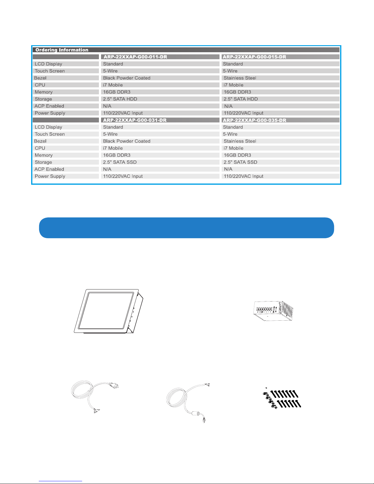
Unpacking ........................................................................................................................................6
Chapter 2 Basics.................................................................................................................7
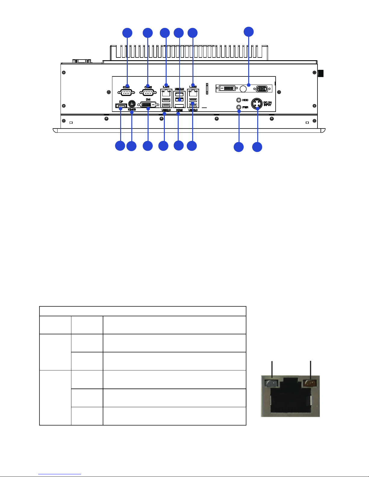
Product overview.......................................................................................................7
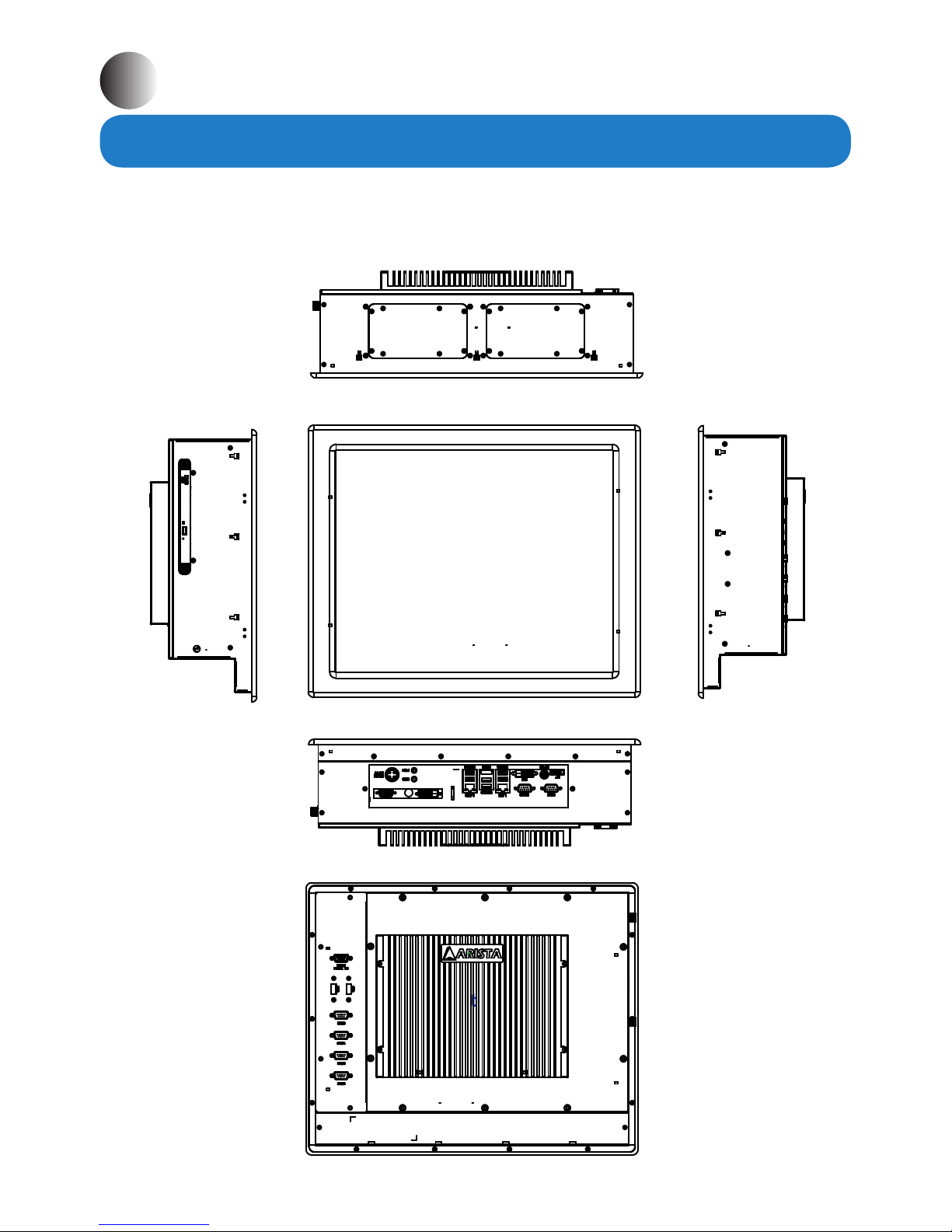
Physical dimensions ....................................................................................................................11
Chapter 3 Connections ...................................................................................................15
Pins in the Serial port (COM1/COM2).......................................................................................16
Pins in the DVI port......................................................................................................................17
Pins in the DC-IN power connector...............................................................................................18
Mounting the computer............................................................................................19
Connecting to a display............................................................................................21
Connecting to keyboard or mouse............................................................................................22
Connecting to network............................................................................................23
Connecting the power supply.............................................................................24
Installing memory module/expansion card..................................................................................26
Adjustment on touch screen..................................................................................29
Chapter 4 BIOS Setup.......................................................................................................31
Introduction....................................................................................................31
Main Menu..........................................................................................33
Advanced Menu............................................................................................34
H/W Monitor Menu..........................................................................................49
Boot Menu................................................................................................50
Security Menu................................................................................................51
Exit Menu................................................................................................52
Chapter 5 Appendix.........................................................................................................53
Care and Maintenance ................................................................................................................53
Product Limited Warranty............................................................................................................54
Disposal and Recycling Information.............................................................................58
Disclaimer and Copyright Notice...............................................................................................58
Contents

4
Features
• Compact design, easy to use, supports hot-plug.
• Use high quality aluminum alloy casting.
• 15”,17” ,19” , 21.5” color TFT LCD display, color supports up to 8 bits per color, total 16.7
million colors.
• Faster in running, lower in power consumption.
• Socket G2(rPGA988B) for Intel® Core i7/i5/i3 Celeron
• Intel® QM77 Chipset, supports SATA / SATA2/ SATA3 hard disks and RAID 0, RAID 1,
Intel Rapid Storage and Intel Smart Response Technology.
• Double Data Rate (DDR) memory technology, supports up to 16GB of system memory,
SupportsDDR31600(OC)/1333/1066non-ECC,un-bueredmemory.
• Supports up to eight USB ports: 2 x USB 3.0, 4 x USB 2.0 ports, support USB 1.0/2.0/3.0
up to 5Gb/s.
• Supports Touch function for quick operation.
• Three video connectors (DVI, HDMI, DP).
• Supports up to six serial ports (COM1~COM6).
• Built-in expansion connectors: MINI-PCIE slot, the PCIE x 16 slot supports Wi-Fi function
and Solid State Drives(SSD), Graphics card.
• Two Dual Gigabit RJ45 LAN ports, provides high-speed and stable network connections.
• Panel mountable for better stability.
• Strengthenedprotectiveglass(anti-reectiveoptional).
• Very high bright option.
• High brightness, contrast and wide viewing angles.
• Built-in lightning & surge protection.
• Super interference rejection.
Applications
• Oceelectronics
• Instrumentation and measuring equipment
• Machine tools
• Audiovisual equipment
• Home appliances
• Communication equipment other than trunk lines
Do not use the products covered herein for the following equipment that demands
extremely high performance in terms of functionality, reliability, or accuracy.
Aerospace equipment
Communication equipment for trunk lines

5
Product specications

6
The unit is shipped with items listed below,inspect them carefully to make sure there is no
damage and all the items are available with your shipment. t ures
ARP-2200AP-G00 Series touch panel computer x1
Unpacking
AC power cable x1
DIN-Rail AC/DC power supply x1
DC power cable x1 Mounting bolts and screws
Ordering information

7
Product overview
Chapter 2 Basics
Side
Side
Bottom
Rear
Top
Front
ARP-2200AP-G00 Series Touch Panel Computer

8

9
Speed LED Activity LED
LED Indications on the LAN port
Status Description
Activity
LED
O No network connection
On Data transmission activity
Speed
LED
O Data transmission at the rate of 10Mbps
Orange Data transmission at the rate of 1Gbps
Green Data transmission at the rate of 100Mbps
PWR LED: Power LED indicator -The LED lights up when you turn on the system,
andbeowhenthesystemisinstandbymode.
HDD LED: Hard Disk Activity LED indicator-The read or write activities of the
hard disk cause the LED to light up.
123456
78
9
10
1112
13
14
1. COM1 port 8. HDD/Power indicator
2. COM2 port 9. USB3.0 ports
3. RJ45 LAN Port(LAN1) 10. HDMI Port
4. USB2.0 ports 11. USB2.0 ports
5. RJ45 LAN Port (LAN2) 12. DVI connector
6. DVI port, COM port(Optional) 13. PS2 keyboard/mouse connector
7. 24V DC power input connector 14. Display port

10
COM3~COM6 ports
Power button connector
CD/DVD ROM Drive Slot
USB Ports

11
ThediagramsbelowshowthephysicalandspecicdimensionsoftheARP-2200AP-G00
Series touch panel computer.
Physical dimension
140.0mm
5.51"
231.6mm
9.12"
111.2mm
4.38"
299.8mm
11.80"
368.6mm
14.51"
276.8mm
10.90"
68.9mm
2.71"
343.7mm
13.53"
261.6mm
10.30"
194.3mm
7.65"
18.7mm
0.73"
353.3mm
13.91"
343.7mm
13.53"
107.4mm
4.23"
For ARP-2215AP-G00
24.7mm
0.97"

12
For ARP-2217AP-G00
269.3mm
10.61"
194.3mm
7.65"
261.6
10.30"
386.7mm
15.23"
353.3mm
13.91"
338.8mm
13.34"
403.4mm
15.88"
119.9mm
4.72"
312.6mm
12.31"
377.2mm
14.85"
138.1mm
5.44" 113.1mm
4.45"
89.5mm
3.52"
144.9mm
5.71"
38.0mm
1.50"

13
For ARP-2219AP-G00
299.7mm
11.80"
145.0mm
5.71"
120.0mm
4.73"
344.9mm
13.58"
370.8mm
14.60"
58.1mm
2.29"
252.4mm
9.94"
82.3mm
3.24" 426.2mm
16.78"
261.6mm
10.30"
91.9mm
3.62"
452.1mm
17.80"
113.1mm
4.46"
89.5mm
3.52"

14
For ARP-2221AP-G00
114.2mm
4.50"
91.7mm
3.61"
194.3mm
7.65"
9.6mm
0.38"
229.9mm
9.05"
501.0mm
19.72"
90.5mm
3.56"
31.2mm
1.23"
146.7mm
5.78"
353.3mm
13.91"
308.7mm
12.15"
533.0mm
20.98"
254.4mm
10.02" 330.0mm
12.99"
L(Overall Length) W(Overall Width) H(Overall Height) Cutout Size
ARP-2215AP-G00 14.51”/368.6mm 11.80”/299.8mm 5.51”/140.0mm 13.75 x 11.10 inch
349.3 x 281.9 mm
ARP-2217AP-G00 15.88”/403.4mm 13.34”/338.8mm 5.71”/144.9mm 15.07 x 12.51 inch
382.8 x 317.8 mm
ARP-2219AP-G00 17.80”/452.1mm 14.60”/370.8mm 5.71”/145.0mm 16.98 x 13.78 inch
431.3 x 350.0 mm
ARP-2221AP-G00 20.98”/533.0mm 12.99”/330.0mm 5.78”/146.7mm 19.92 x 12.35 inch
506.0 x 313.7 mm

15
Connectors are located at the bottom of ARP-2200AP-G00 Series touch panel computer.
Chapter 3 Connections
This section describes the connections/connectors available on the ARP-2200AP-G00 Series
touch panel computer.

16
Pins in the serial port (COM1/COM2)
6789
1 2 3 4 5
Pin NO. RS-232 mode RS-422 mode RS-485 mode
1 DCD TX- RTX-
2 RXD RX+ N/A
3TXD TX+ RTX+
4 DTR RX- N/A
5 GND GND GND
6 DSR N/A N/A
7RTS N/A N/A
8 CTS N/A N/A
9 +5V/+12V/RI# +5V/+12V/RI# +5V/+12V/RI#

17
Pins in the DVI port
8
1234 5 6 7
10 11
19 20 21 22 23 24
25
27 28
29
26
1817
12 13 14 15 169
Pin NO. Pin Assignment Description
1 RXD2- T.M.D.S Data 2-
2 RXD2+ T.M.D.S Data 2+
3 GND T.M.D.S Data 2 Shield
4 NC No connection
5 NC No connection
6 SCL DDC clock
7 SDA DDC data
8 NC No connection
9 RXD1- T.M.D.S Data 1-
10 RXD1+ T.M.D.S Data 1+
11 GND T.M.D.S Data 1 Shield
12 NC No connection
13 NC No connection
14 DVIVCC + 5V power input
15 GND Ground
16 HPD Hot plug detect
17 RXD0- T.M.D.S Data 0-
18 RXD0+ T.M.D.S Data 0+
19 GND T.M.D.S Data 0 Shield
20 NC No connection
21 NC No connection
22 GND T.M.D.S Clock Shield
23 RXDC+ T.M.D.S Clock +
24 RXDC- T.M.D.S Clock -
25 NC No connection
26 NC No connection
27 NC No connection
28 NC No connection
29 NC No connection

18
Pins in the DC-IN power connector
23
4 1
Pin NO. Denition
1 GND
2 24V
3 GND
4 24V

19
Mounting the computer
Panel mounting
The ARP-2200AP-G00 Series touch panel computer can be placed on a shelf, table,
or mounted onto a wall or board. To mount it onto a wall or board, you will require the
mounting bolts and screws found in the accessory box.
Please follow the steps shown in the diagram below:
Step2. Situate the bottom cover of ARP-2200AP-G00 Series touch panel computer within
the place on a board or a wall where the mounting holes are pre-drilled. Turn to the
back of the unit and the wall, align the mounting bolts installed on the four sides of ARP-
2200AP-G00 Series touch panel computer with the mounting holes on the wall or board.
Step1. There are mounting slots located on the four sides of the ARP-2200AP-G00 Series
touchpanelcomputer.Asshowninthegurebelow,putandslidethesuppliedmounting
bolts into the mounting slots.
Wall or board
Mounting hole
Mounting bolt
Mounting slot
Mounting bolt

20
Step3. Tighten the "M4" sized mounting screws into the wall and board through the
mounting bolts and mounting holes and make sure the ARP-2200AP-G00 Series touch
panel computer is correctly and securely seated onto the board or wall.
This manual suits for next models
3
Table of contents
Other Arista Industrial PC manuals
Popular Industrial PC manuals by other brands

Siemens
Siemens SIMATIC IPC547C Getting started

Siemens
Siemens SIMATIC IPC347G operating instructions

Siemens
Siemens SIMATIC HMI IPC677C operating instructions

GIGAIPC
GIGAIPC QBiX-Pro-TGLA1135G7H-A2 quick start guide

Moxa Technologies
Moxa Technologies DRP-C100 Series Hardware user manual

Ariesys
Ariesys ARL998 User's reference manual

Asus
Asus EBE-4U user manual

Siemens
Siemens SIMATIC IPC427D operating instructions

Onlogic
Onlogic ML510G-50 product manual

Mouser Electronics
Mouser Electronics AIO-CM4-101 user manual

Mitsubishi Electric
Mitsubishi Electric MELIPC MI5000 Series user manual

Avalue Technology
Avalue Technology SID-15W9 Quick reference guide