Arista MicroBox-7824B-E01 User manual

This manual is a user guide for Microbox-7824B E-Series Fanless
Industrial MicroBox Computer. It includes detailed description about how
to install and operate the product. Arista Corporation recommends users to
read through the entire manual and follow instructions to avoid any kind of
obscurity in using the product. For any questions or support, please call us
at 1.877.827.4782 Monday through Friday 8:00am to 5:00PM Pacic Time.
USER MANUAL
Talk to us. We listen.
MicroBox-7824B E-Series Fanless Industrial MicroBox Computer
MicroBox-7824B-E01 MicroBox-7824B-E02

2
Product safety precautions
Important: Read all the contents of this instruction manual carefully before
using the Microbox-7824B E-Series Fanless Industrial MicroBox Computer.
Read this document before installation,configuration and operation of this equipment.
Users are required to familiarize with all the information and applicable standards prior to
using this manual. This manual should be saved for future reference and use.
• Relative humidity: 25%~80%
• Storage temperature: -20oC to 60oC(-4F to 140F)
• Operation temperature: 0~50oC(32F to 122F)
• Unplug the unit when not in use for an extended period of time.
• Consult a service technician if the Microbox-7824B E-Series Fanless Industrial
MicroBox Computer does not operate normally when you have followed the
instructions in this manual.
• Do not attempt to repair this product yourself. Always get a qualified service
technician to carry out adjustments or repairs.
• Do not place heavy objects on the unit.
• Alwaysusethepowercordsuppliedwiththisunit.Foranyreasonadierentpower
cordisused,itshouldbecertiedbylocalandnationalstandardsandusedunder
guidance of authorized technician.
• Never use a faulty power cord with this unit. Please contact the manufacturer or
nearest authorized repair service right away for a replacement if damaged power
cord is received.
• The power supply cord is used as the main disconnect device. Ensure that the socket
outlet is easily accessible after installation.
• Overloaded AC outlets, extension cords, frayed power cords, and broken plugs are
extremelydangerous.Theymay,andcan,resultinanelectricalshockorrehazard.
Call an authorized service technician for any replacements.
• Hands must be dry when plugging the power cord into an AC outlet to prevent
electrical shock. Do not damage the power cord by disassembling, bending, pulling
orexposingittoheatasitmaycauseareorelectricalshock.
• Make sure to completely insert the power plug into an AC outlet. Insecure
connectionscancausere.
• Ensure that the power source is grounded correctly.
• Unplug the unit if cleaning is needed. The unit may be wiped with a dry or slightly
dampclothwhenthepoweriso.

3
Contents
Product safety precautions ................................................................................................2
Contents...............................................................................................................................3
Chapter 1 Welcome .............................................................................................................4
Introduction......................................................................................................................................4
Features............................................................................................................................................5
Product specications....................................................................................................................6
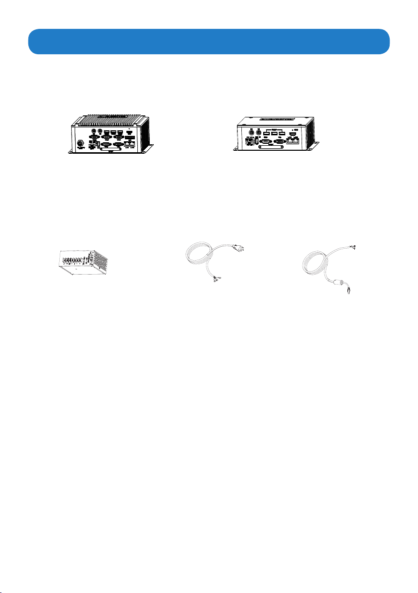
Unpacking ........................................................................................................................................7
Chapter 2 Basics.................................................................................................................8
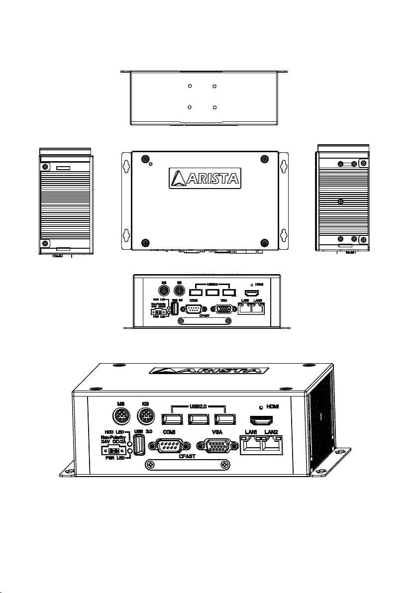
Product overview.......................................................................................................8
Physical dimensions ....................................................................................................................12
Chapter 3 Connections ...................................................................................................14
Pins in the Serial port( COM1~COM4).......................................................................................15
Pins in the VGA port......................................................................................................................16
Pins in the GPIO port (only for MicroBox-7824B-E01)..............................................................17
Pins in the DC-IN power connector...............................................................................................18
Mounting the MicroBox computer............................................................................................19
Connecting to display............................................................................................23
Connecting to touch screen............................................................................................24
Connecting to keyboard or mouse............................................................................................24
Connecting to network............................................................................................25
Connecting the power supply.............................................................................26
Connecting the battery power (only for MicroBox-7824B-E01).............................................28
Installing memory module/expansion card.............................................................................29
Chapter 4 BIOS Setup.......................................................................................................32
Introduction....................................................................................................32
Entering the setup..............................................................................................33
Main Menu...........................................................................................35
Advanced Menu.............................................................................................36
Chipset Menu.....................................................................................43
Security Menu.................................................................................................46
Boot Menu................................................................................................47
Save&Exit Menu.........................................................................................48
Chapter 5 Appendix.........................................................................................................49
Care and Maintenance .................................................................................................................49
Product Limited Warranty............................................................................................................50
Disposal and Recycling Information.............................................................................55
Disclaimer and Copyright Notice................................................................................................55
Contents

4
Chapter 1 Welcome
Arista MicroBox-7824B E-Series is the most advanced industrial-level fanless computer.
This unit delivers high-performance with low-power consumption, the wall mount chassis
is ideal for rugged applications. MicroBox-7824B E-Series industrial computer is equipped
with an advanced convection cooling module for a fanless operation. This improves
computer speed while minimizing movements on the internal components of MicroBox-
7824B E-Series.
Introduction
Applications
• Oceelectronics
• Instrumentation and measuring equipment
• Machine tools
• Audiovisual equipment
• Home appliances
• Communication equipment other than trunk lines
Do not use the products covered herein for the following equipment that demands
extremely high performance in terms of functionality, reliability, or accuracy.
Aerospace equipment
Communication equipment for trunk lines

5
Features
• Compact and fanless design, easy to use, supports hot-plug.
• Use high quality aluminum alloy casting.
• Operates faster with low power consumption.
• Intel 1.9GHz E3845 Quad Core Atom Processor.
• Supports Smart Battery for portable applications (for MicroBox-7824B-E01).
• Double Data Rate (DDR3) memory technology, supports up to 8GB of system memory
using 1333MHz DIMM.
• Supports up to four USB ports.
• Intel Gen7 Intel Graphics DX 11, OGL3.2., supports display resolution up to 1920×1080.
• Supports up to four serial ports (for MicroBox-7824B-E01), and all the
serial
ports(COM1~COM4)canbeconguredtoRS-232,RS-422orRS-485modeinBIOSsetup.
• Build-in expansion connectors: CFAST Card slot, MINI-PCIE slot, the MINI-PCIE slot
supports Wi-Fi function and Solid State Drives(SSD).
• Supports programmable GPIO port (for MicroBox-7824B-E01).
• Two Dual Gigabit RJ45 LAN ports, provides high-speed and stable network connections.
• Wall and DIN-Rail mount for better stability.

6
Product specications
System
CPU Intel 1.9GHz E3845 Quad Core Atom Processor
Chipset Intel E3845 chipset
Memory Up to 8GB, DDR3 SO-DIMM (1333MHz)
Video interface VGA, HDMI
Resolution Up to 1920 x 1080
Storage option SATA DOM, 2.5" HDD, 2.5" SSD, CFast Card
Compactash N/A
GPIO 8-bit GPIO
BIOS American megatrend
Connectors
Video connector 1 x VGA, 1 x HDMI
CFast Card 1 x CFast Card connector
USB port 3 x USB2.0 port, 1 x USB3.0 port
Serial port 4 x RS-232/422/485 BIOS Selectable (MicroBox-
7824B-E01)
1 x RS-232/422/485 BIOS Selectable (MicroBox-
7824B-E02)
GPIO 1 x GPIO port (for MicroBox-7824B-E01)
LAN 2 x Gigabit
Keyboard/Mouse 1x PS2 keyboard, 1x PS2 mouse
Power 1x DC-IN power, 1 x Battery power input(for MicroBox-
7824B-E01)
Operating system
OS Support Windows 7 & up
Physical information
Mounting
Wall mounting, DIN-Rail mounting
Physical dimension MicroBox-7824B-E01
:
8.84 X 3.47 X 5.53 inch/ 224.4 X 88.1 X 140.5 mm (L X H X D)
MicroBox-7824B-E02
:
7.71 X 2.50 X 4.59 inch/ 195.8 X 63.5 X 116.5 mm (L X H X D)
Net weight MicroBox-7824B-E01
:
2.3kg, MicroBox-7824B-E02
:
2.0kg
Mechnical information
Power requirement ( Max ) 24VDC/0.7A (DIN-Rail power supply)
Power consumption ( Max ) 17W
Recommended power supply 24W
Heat dissipation 58 BTU/hr
Operation temperature 0~50OC [32~122F]
Storage temperature -20~60OC [-4~140F]
Relative humidity 20~90% RH [no condensation]

7
Open the package and inspect items carefully to make sure no item is damaged and all
items listed are present in your package. t ures
MicroBox-7824B-E01 x1 MicroBox-7824B-E02 x1
Unpacking
AC power cable x1
DIN-Rail AC/DC power supply x1 DC power cable x1

8
Product overview
Chapter 2 Basics
Rear
Right
Top
Left
Bottom Front
MicroBox-7824-E01

9
I/O Panel
1234
5
6
7
8
9
11 10
12
13
1. PS/2 Mouse connector 8. CFAST card slot
2. PS/2 Keyboard connector 9. USB port
3. USB ports 10. Power LED(up)/HDD LED(down) indicator
4. HDMI port 11. 24V DC-IN power connector
5. GPIO port 12. Battery power input connector
6. RJ45 LAN port 13. Serial ports (COM1~COM4)
7. VGA port
Speed LED Activity LED
LED Indications on the LAN port
Status Description
Activity
LED
O No network connection
On Data transmission activity
Speed
LED
O Data transmission at the rate of 10Mbps
Orange Data transmission at the rate of 1Gbps
Green Data transmission at the rate of 100Mbps
PWR LED: Power LED indicator -The LED lights up when you turn on the system,
andswitchesoinstandbymode.
HDD LED: Hard Disk Activity LED indicator- Read or write activities of the hard
disk cause the LED to light up.

10
Rear
Right
Top
Left
Front
MicroBox-7824-E02

11
I/O Panel
1234
5678911 10
1. PS/2 Mouse connector 7. CFAST card slot
2. PS/2 Keyboard connector 8. Serial ports (COM1)
3. USB2.0 port x 3 9. USB3.0 port x 1
4. HDMI port 10. Power LED(up)/HDD LED(down) indicator
5. RJ45 LAN port x 2 11. 24V DC-IN power connector
6. VGA port
Speed LED Activity LED
LED Indications on the LAN port
Status Description
Activity
LED
O No network connection
On Data transmission activity
Speed
LED
O Data transmission at the rate of 10Mbps
Orange Data transmission at the rate of 1Gbps
Green Data transmission at the rate of 100Mbps
PWR LED: Power LED indicator -The LED lights up when you turn on the system,
andswitchesoinstandbymode.
HDD LED: Hard Disk Activity LED indicator- Read or write activities of the hard
disk cause the LED to light up.

12
The diagrams below show the physical dimensions of the MicroBox-7824B E -Series
fanless industrial microbox computer.
Top View
Physical dimension
MicroBox-7824B-E01
L(Overall length) H(Overall height) D(Overall width) Weight
8.84”/224.4mm 3.47”/88.1mm 5.53”/140.5 mm 5.1 lb/2.3 kg
108.0 mm
4.25"
140.5 mm
5.53"
224.4 mm
8.84"
212.6 mm
8.37"
Front View
201.4 mm
7.93"
88.1 mm
3.47"
MicroBox-7824-E01

13
Top View
81.0mm
3.19"
116.5 mm
4.59"
195.8mm
7.71"
185.0 mm
7.28"
Front View
173.0 mm
6.81"
63.5 mm
2.50"
MicroBox-7824-E02
MicroBox-7824B-E02
L(Overall length) H(Overall height) D(Overall width) Weight
7.71”/195.8mm 2.50”/63.5mm 4.59”/116.5 mm 4.4lb/2.0 kg

14
Connectors are located on the front panel of MicroBox-7824B-E01 microbox computer.
Connectors are located on the front panel of MicroBox-7824B-E02 microbox computer.
Chapter 3 Connections
This section describes connections/connectors available on MicroBox-7824B E-Series
microbox
computer
.

15
Pins in the serial port(COM1~COM4)
6789
1 2 3 4 5
Pin NO. Denition(RS-232 mode) Denition(RS-422/RS-485 mode)
1 DCD, data carrier detect TX-, Transmit data ground (RS-422/RS-485)
2 RXD, Receive data TX+, Transmit data(RS-422/RS-485)
3TXD, Transmit data RX+, Receive data (RS-422)
4 DTR, Data terminal ready RX-, Receive data ground (RS-422)
5 GND, Signal ground GND, Signal ground
6 DSR, Data set ready N.C.
7 RTS, Request to send N.C
8 CTS, Clear to send N.C
9 Ring-IN, Ring indicator N.C.
Note: COM1~COM4 ports can be set to RS-232 mode(default), RS-422 mode or RS-485 Mode.

16
Pins in the VGA port
2345
6
78
9
10
1112131415
Pin NO. Pin Assignment Denition
1 VGA R VGA Red signal
2 VGA G VGA Green signal
3 VGA B VGA Blue signal
4 NC No connection
5 GND Ground
6 GND Ground
7 GND Ground
8 GND Ground
9 NC No connection
10 GND Ground
11 NC No connection
12 CRT DDC Data The data of display data channel
13 VGA HS VGA H-Sync signal
14 VGA VS VGA V-Sync signal
15 CRT DDC Clock The clock of display data channel
1
Pins in the GPIO port (only for MicroBox-7824B-E01)

17
Pins in the GPIO port (only for MicroBox-7824B-E01)
123456 78910
The GPIO (General Purpose Input/Output) port is optional and can be used as
expansion input or output ports by software routines as needed.
Pin NO. Pin Assignment Denition
1 +V5S +V5S
2 I/O_BUS_GPIO1 GPIO input
3 I/O_BUS_GPIO2 GPIO output-
4 I/O_BUS_GPIO3 GPIO input
5 I/O_BUS_GPIO4 GPIO output
6 I/O_BUS_GPIO5 GPIO input
7 I/O_BUS_GPIO6 GPIO output
8 I/O_BUS_GPIO7 GPIO input
9 I/O_BUS_GPIO8 GPIO output
10 GND Ground
GPIO
settings
Input Ouput
I/O_BUS_GPIO1 GPIO42 0xFFF240 bit2 I/O_BUS_GPIO2 GPIO71 0xFFF270 bit1
I/O_BUS_GPIO3 GPIO50 0xFFF250 bit0 I/O_BUS_GPIO4 GPIO16 0xFFF210 bit6
I/O_BUS_GPIO5 GPIO52 0xFFF250 bit2 I/O_BUS_GPIO6 GPIO75 0xFFF270 bit5
I/O_BUS_GPIO7 GPIO43 0xFFF240 bit3 I/O_BUS_GPIO8 GPIO81 0xFFF280 bit1

18
Pins in the DC-IN power connector
2
Pin NO. Denition
1 GND
2 24V
Pin NO. Denition
1 24V
2 GND
1
Or

19
Mounting the MicroBox computer
1. Wall mounting
There are two methods to mount the MicroBox-7824B E-Series industrial microbox
computer: Wall and DIN-rail mounting.
The MicroBox-7824B E-Series microbox computer can be placed on a shelf, table,
or mounted onto a wall or board. To mount it onto a wall or board, you will require the
mounting screws found in the accessory box.
Please follow the steps shown in the diagram below:
Step1. Situate the four “#8-32UNC” size screws on a board or a wall and use a screwdriver
tormlyxthemintothewallorboard(Donotcompletelytightenthescrews).
Step2. Then put the MicroBox-7824B E-Series microbox computer onto the screws through
the mounting hole on the computer.
Wall or board
(side view)
Screws
Wall or board
Wall or board
Mounting hole

20
Step3. Tighten the screws and make sure the MicroBox-7824B E-Series computer is
correctly and securely seated onto the board or wall.
Screw tightened
It is very important to place the unit in a suitable environment. Make sure the
area is well ventilated, out of direct sunlight, away from sources of excessive
dust, dirt, heat, water, moisture and vibration.
Other manuals for MicroBox-7824B-E01
1
This manual suits for next models
1
Table of contents
Other Arista Industrial PC manuals
Popular Industrial PC manuals by other brands

Kontron Embedded Computers
Kontron Embedded Computers V Panel Express user manual

Moxa Technologies
Moxa Technologies UC-8112-LX STK Hardware Quick Installation Guide

Neousys Technology
Neousys Technology POC-400 Series Quick installation guide

Contec
Contec VPC-1600 user manual

Nexcom
Nexcom NDiS B560-Q user manual

Advantech-DLoG
Advantech-DLoG DLT-V72 Series manual