Ariston SOLARcomfort User manual

SOLARcomfort
Solar Hot Water
Systems
2 & 3 Collector
Sets
Installation Instructions
LEAVE THESE INSTRUCTIONS WITH THE
END USER
Country of Destination GB/IE

1
TABLE OF CONTENTS
1. GENERAL INFORMATION...............2
1.1 GUARANTEE .........................................2
1.2 SYSTEM CONTENTS ...............................2
1.3 SYSTEM INSTRUCTION BOOKS..................2
1.4 SOLARCOMFORT .................................3
1.5 LIFESTYLE ............................................3
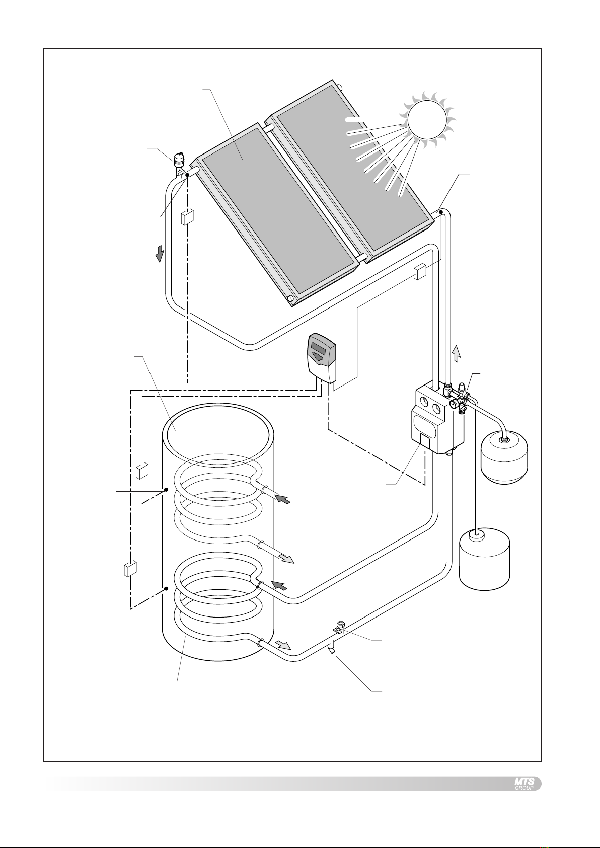
1.6 HOW THE SYSTEM WORKS......................3
2. SAFETY............................................5
3. TECHNICAL DATA............................6
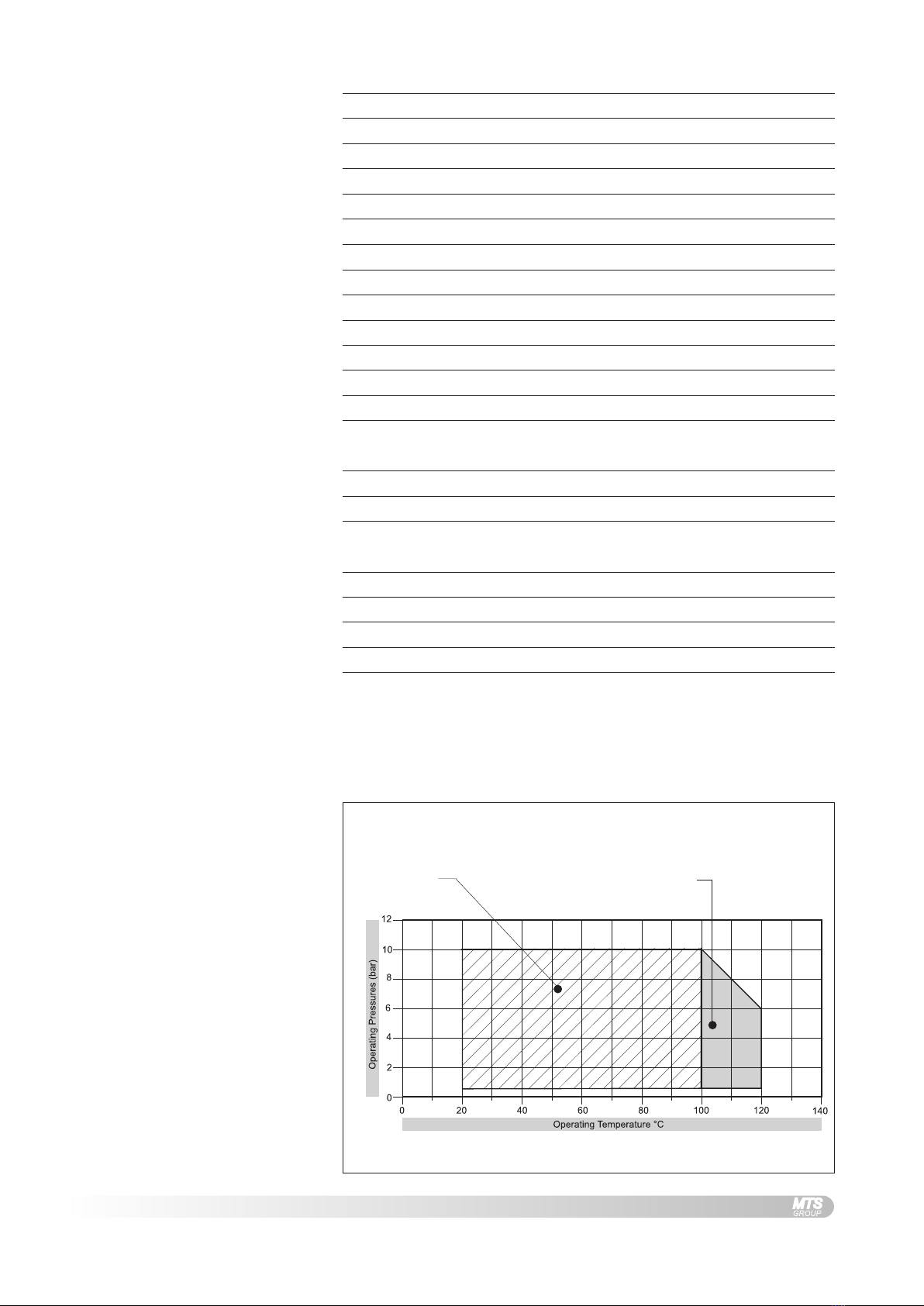
3.1 TEMPERATURE/PRESSURE .......................6
3.2 COMPONENT LIST FOR 2 COLLECTOR SYSTEM
7
3.3 COMPONENT LIST FOR 3 COLLECTOR SYSTEM
8
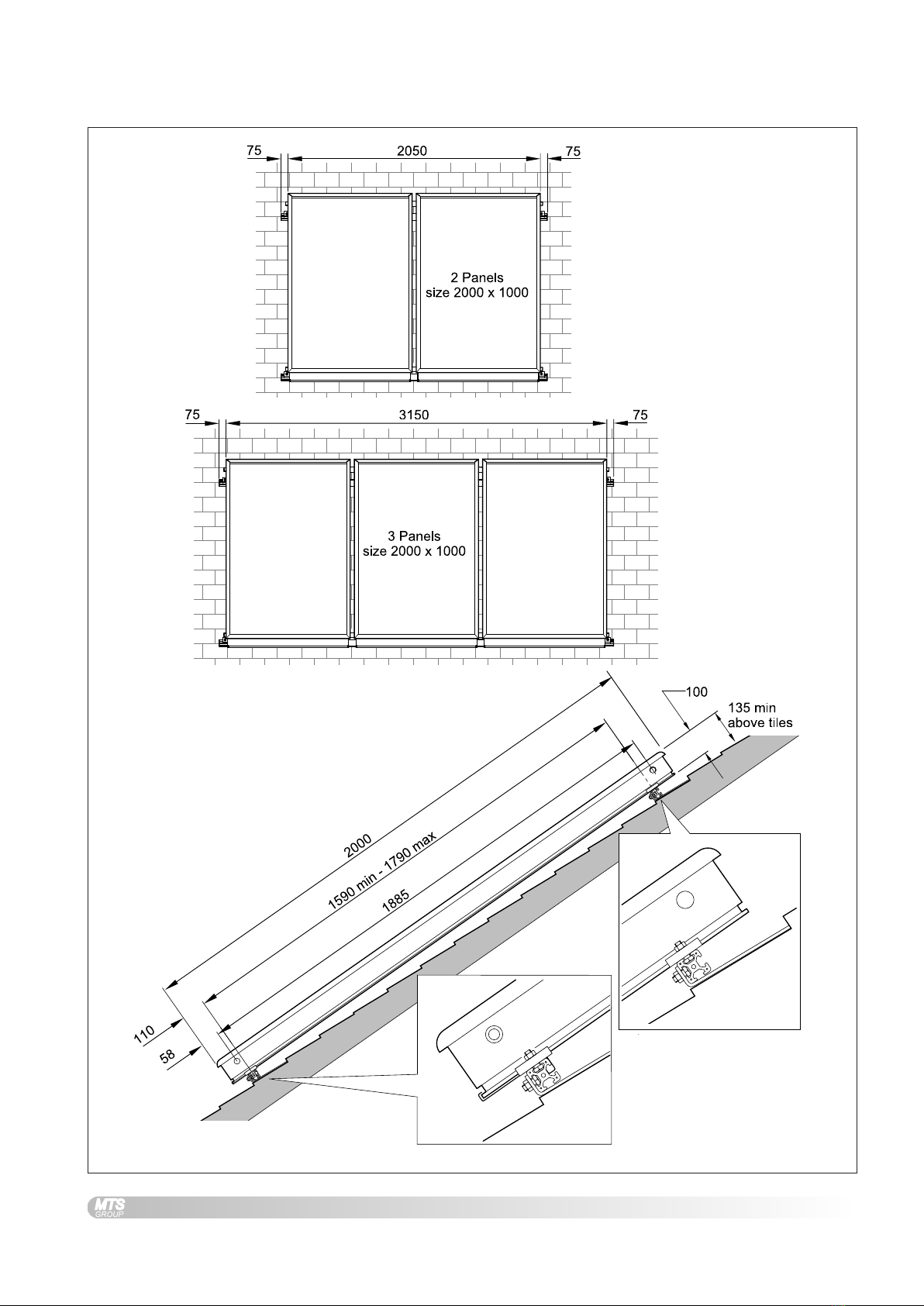
3.4 COLLECTOR DIMENSIONS ........................9
3.5 FIXING STRAPS DIMENSIONS .................10
4. REGULATIONS & STANDARDS.....11
4.1 WATER REGULATIONS ..........................11
4.2 BUILDING REGULATIONS........................11
4.3 GENERAL GUIDANCE ............................11
4.4 BRITISH & EUROPEAN STANDARDS .........12
4.5 UK REGULATIONS (WATER HEATING) .....12
4.6 UK REGULATIONS (CONSTRUCTION) .......12
4.7 EU DIRECTIVES ..................................13
4.8 OTHER PUBLICATIONS ..........................13
4.9 ELECTRICAL CONNECTION .....................13
4.10 THERMAL INSULATION ...........................13
5. INSTALLATION ...............................14
5.1 TOWN & COUNTRY PLANNING ...............14
5.2 HOUSE INSURANCE ..............................14
5.3 RISK ASSESSMENT ..............................14
5.4 ROOF CONDITION ................................14
5.5 POSITIONING COLLECTORS ....................14
5.6 CONSIDERATIONS FOR POSITIONING
COLLECTORS ......................................14
5.7 COLLECTOR INCLINATION .......................15
5.8 PIPEWORK & FITTINGS .........................15
5.9 INSULATION.........................................15
5.10 SIZING OF PIPES .................................15
5.11 PIPEWORK..........................................16
5.12 COLLECTOR COUPLINGS .......................16
5.13 COLLECTOR CONFIGURATIONS ...............17
5.14 TWO COLLECTOR SCHEMATIC ................18
5.15 THREE COLLECTOR SCHEMATIC .............19
5.16 FIXING STRAPS ...................................20
5.17 ROOF TYPES ......................................21
5.18 COLLECTOR FIXINGS ............................22
5.19 COLLECTOR FITTING PROCEDURE...........23
5.20 PLUMBING CONNECTIONS......................28
6. COMMISSIONING & SERVICING..28
7. FLAT ROOF/GROUND MOUNTING
KIT ..................................................29
7.1 COMPONENT LIST ................................29
7.2 ANGLE OF INCLINATION .........................29
7.3 COLLECTOR ORIENTATION .....................30
7.4 DIMENSIONS .......................................30
7.5 FLAT ROOF CONDITION ........................30
7.6 GROUND PREPARATION.........................31
7.7 ASSEMBLY ..........................................31

2
1. GENERAL
INFORMATION
This manual is an integral and essential part of the product. It should be
kept with the product.
Please read carefully the instructions and notes about SOLARcomfort
contained in this manual as they provide important information regarding
the safe installation of the Solar Collectors.
IMPORTANT
Failure to follow these instructions correctly may invalidate the
guarantee.
IMPORTANT
Solar domestic hot water heating systems must be installed to
comply with the current Building Regulations, British Standards
and any applicable local regulations.
The SOLARcomfort Collectors are guaranteed for 5 years against
manufacturing defect - see terms and conditions of guarantee on back
page.
The complete SOLARcomfort solar water heating system is supplied in
the following consignments:-
1. 800201 Collector 1 per box
2. 3107024/5 Roof Fittings Kit 1 cardboard tube
3. 3820011/2 System Components 1 box
4. 3820001 Tyfocor antifreeze heat transfer fluid
1 x 20l container
The following instruction booklets are supplied with a complete
SOLARcomfort solar water heating system:-
1. SOLARcomfort Solar HotWater Systems Collectors 2 & 3 Collector
Set.
Covers collector installation and plumbing connection.
Supplied in System Components box.
2. SOLARcomfort Solar HotWater Systems Pump Group 40/60.
Coversinstallation, plumbingconnection, systemfilling, flushingand
commissioning.
Supplied in System Components box.
3. Solar Controller AST 100
Covers installation, wiring connection and User Instructions.
Supplied in System Components box.
1.1 GUARANTEE
1.2 SYSTEM CONTENTS
1.3 SYSTEM INSTRUCTION BOOKS

3
SOLARcomfort systems are highly efficient and provide cost savings on
the energy used for heating hot water wherever they are used in the UK.
However, the savings made will depend on local climate, installation
characteristics and the household’s domestic hot water requirements.
It is important that the SOLARcomfort system is correctly sized for the
local climate condition and the householders requirements.
After installation of the SOLARcomfort system, changes to the
householders use of hot water will be beneficial. Simple changes such as
bathingintheeveninginsteadof the morningandputting automatic washing
machines on when free hot water is available by solar energy.
In addition, the timing of the dwelling’s boiler controls must be modified to
ensure the‘hot water ON’time is set so that the water temperature in the
cylinder is at a minimum by the start of the ‘solar day’.
The solar collectors are heated by the sun’s rays. The heat generated is
storedin a hotwaterstorage cylindere.g.AristonPrimotwin coilstainless
steelcylinder. Thesystemcontroller continuallycompares the temperature
ofthe water withinthe cylinderwith the temperatureof the solarcollectors.
Wheneverthe solarcollectors arehotter thanthe water withinthe cylinder,
thecontroller switchesonthe system’s circulatingpump. Thetemperature
differential between the collectors and the cylinder is set via the AST 100
Solar Controller. The heat transfer fluid within the solar system is then
circulatedthroughthe collectorsandthecylinder’sheat exchanger,heating
the cylinder in just the same way as a central heating boiler.
The cylinder typically has two coils (heat exchangers), the lower coil is
heated by the solar system, therefore solar is the primary heat source.
Theupper cylinder isheated by anauxiliary heat source,typically acentral
heating boiler, which is used to heat water when there is insufficient heat
generated by the solar system. The Ariston PrimoTwin cylinder also has
twoimmersion heatersmaking it suitableforelectric onlyheating systems.
The SOLARcomfort system is a forced circulation sealed system and
therefore requires an expansion vessel and a pressure relief valve (PRV),
both supplied with SOLARcomfort.
Theairseparatorwithanintegralmanualairventtogetherwithan automatic
air vent positioned at the highest point on the system ensures that the
sealed system remains free of air.
1.6 HOW THE SYSTEM WORKS
See fig. 1.6A
1.4 SOLARCOMFORT
1.5 LIFESTYLE

4
FIG. 1.6ASOLAR BASIC PRINCIPLES
Roof mounted collectors
(two collector system shown)
Pump group Expansion
vessel
Solar system
low level fill
point
Ariston ITSI 210/300
twin coil cylinder
Upper coil
heated by boiler
or other heat
source
Lower coil heated by
solar energy
AST 100
Controller
Air vent
PRValve
Solar system
drain point
Temperature
Sensor S1
Temperature
Sensor S3
Temperature
Sensor S2 PRV discharge
vessel
Energy
Monitoring
Sensor S4
(option)

5
2. SAFETY WARNING - RISKTO LIFE
Correct procedures must be followed when lifting the collectors.
To satisfyHealth and Safety requirements relatingto the construction
industry, the use of a crane or other lifting device may be required.
Take appropriate precautions to prevent accidents and falls when
working on roofs.
Ensure correct personal protective clothing and safety equipment
are used when working on roofs.
Ensure that collectors lifted onto the roof or scaffold are always
secured to prevent them slipping and falling off the roof. Serious
injury or death may result from collectors falling.
WARNING
The collectors must be correctly secured to the roof. The roof must
be of adequate structure to support the collectors.
WARNING
During operation and commissioning the temperature of the heat
transferfluidwithin the system and collectorscanreachtemperatures
high enough to present a risk of scalding. Never loosen fittings or
open vents when the system is hot.
WARNING
TYFOCOR LS HeatTransfer Fluid.
Although non-toxic it should not be swallowed.
Refer to label on its container for storage and safety information.
A detailed technical specification is available from Ariston on request.
Caution
SOLARcomfort should be installed and commissioned by approved
contractors. Failure to do so may invalidate the warranty.
Caution - Risk of damage to collectors
IMPORTANT! Always keep the glass side of the collectors fully
covered until the system is filled and ready for operation.
Always transport the collectors in an upright position. Never position the
collectors with the glass side facing down.
Leave collectors in their packaging until the time of installation. Do not
allow the bottom side of the collectors to be damaged by sharp objects.
Never leave the collectors with the glass side down when they could be
exposed to theweather,as rainwatercould infiltrate thecollectorandcause
condensation within the collector.
Note:
Optional lifting handles are available
from Ariston (code 3107023).

6
3. TECHNICAL DATA
Operating pressure and
temperature must be within
the limits depicted by the
hatched area
Operating temperatures above
100°C as depicted by the
shaded area must be avoided
for continuous operation
FIG. 3.1ATEMPERATURE PRESSURE DIAGRAM
COLLECTORS
Weight - each - empty 38kgs
Total surface area - each 2m²
Aperture area - each 1.83m²
Absorber area - each (evaluated according to EN12975:2001) 1.76m²
Capacity - each 1.5l
Maximum operating pressure 6Bar
Pressure loss 10mbar
Output - each 100l/h
Plate absorption 95%
Plate emission 5%
*Stagnationtemperature 167°C
Inlets/Outlets - copper Ø22mm
Frame Grey aluminium UV resistant
EXPANSIONVESSEL
2 collector system 25l
3 collector system 25l
HEATTRANSFER FLUID
Type Tyfocor LS
Use undiluted 100%
Weight 1.04kg/l
Frost Protection to -28°C
*The stagnation temperature was calculated
for:-
Insolation level of 1000W/m²
Atmospheric temperature value30°
3.1 TEMPERATURE / PRESSURE

7
FIG. 3.2A2 COLLECTOR SYSTEM COMPONENT LIST
3.2 COMPONENT LIST FOR 2
COLLECTOR SYSTEM
Listed below are all the components required to fit the collectors for the
SOLARcomfort 2 collector system.
feR noitpircseD ytQ tnemngisnoC dekcaP
1mm0002xmm0001srotcelloC2xobrep1laudividnI
2mm0022htgnelsliaRtroppuS2
tikgnixiffooRebutdraobdraC1
3spartsgnixift
rohS4
4spartsgnixifgnoL4
5)"2x21.oN(05x6ØswercsgnixifpartS21
6)trohs(spmalcretuO4
7)gnol(spmalcrennI2
8stekcarbmotto
brotcelloC4
9stlobleetssselniatsxeh52x8M21
01stunleetssselniatsxeh8M
)eraps6cni(
81
11srehsawleetssselniats8M
)swercsdoowrof21cni(
42
21mm22gnilpuocnoisserpmoC3
ssarbrotcelloC
tiksgnittif
metsySnidekcaP
xobstnenopmoC
31mm22dnepotsnoisserpmoC2
41mm22x"½xmm22TnoisserpmoC2
51hsubrecudeR"8/3ot"½1
61m1xmm22epipelbixelfdetalusnI2
noitcennocelbixelF
tik
metsyS
nidekcaP
xobstnenopmoC
71mm22gnilpuocnoisserpmoC2
81tnevriacitamotuA1
metsySnidekcaP
xobstnenopmoC
91M"8/3xF"8/3
evlavgnitalosI1
02snoitcurtsnIrotcelloC1
12tekcoptatsomrehT"½1rellortnoC001TSAhtiwnidekcaP
Roof Fixing Kit (cardboard tube)
Collector brass fitting kit
Flexible connecting kit

8
FIG. 3.3A3 COLLECTOR SYSTEM COMPONENT LIST
3.3 COMPONENT LIST FOR 3
COLLECTOR SYSTEM
Listed below are all the components required to fit the collectors for the
SOLARcomfort 3 collector system.
Roof Fixing Kit (cardboard tube)
Collector brass fitting kit
Flexible connecting kit
feRnoitpircseDytQtnemngisnoCdekcaP
1mm0002xmm0001srotcelloC3xobrep1laudividnI
2mm0033htgnelsliaRtroppuS2
tikgnixiffooRebutdraobdraC1
3spartsgnixift
rohS6
4spartsgnixifgnoL6
5)"2x21.oN(05x6ØswercsgnixifpartS81
6)trohs(spmalcretuO4
7)gnol(spmalcrennI4
8stekcarbmotto
brotcelloC6
9stlobleetssselniatsxeh52x8M42
01stunleetssselniatsxeh8M
)eraps8cni(
42
11srehsawleetssselniats8M
)swercsdoowrof81cni(
43
21mm22gnilpuocnoisserpmoC5
ssarbrotcelloC
tiksgnittif
metsySnidekcaP
xobstnenopmoC
31mm22dnepotsnoisserpmoC2
41mm22x"½xmm22TnoisserpmoC2
51hsubrecudeR"8/3ot"½1
61m1xmm22epipelbixelfdetalusnI2
noitcennocelbixelF
tik
metsyS
nidekcaP
xobstnenopmoC
71mm22gnilpuocnoisserpmoC2
81tnevriacitamotuA1
metsySnidekcaP
xobstnenopmoC
91M"8/3xF"8/3
evlavgnitalosI1
02snoitcurtsnIrotcelloC1
12tekcoptatsomrehT"½1rellortnoC001TSAhtiwnidekcaP

9
3.4 COLLECTOR DIMENSIONS
FIG. 3.4ACOLLECTOR DIMENSIONS

10
3.5 FIXING STRAPS DIMENSIONS
FIG. 3.5AFIXING STRAP DIMENSIONS
LONG
SHORT

11
4. REGULATIONS &
STANDARDS
SOLARcomfort hot water heating systems should be installed in
compliance with the following standards and regulations.
Water Supply (Water Fittings) Regulations 1999 / www.wras.co.uk
These regulations (bye-laws in Scotland) ensure a good supply of
wholesome water and that only approved materials, pipes and fittings are
used to convey water.
Theseare statutory documents and takepriorityoverall otherregulations
and recommendations. The installation of an unvented hot water storage
cylinderis classifiedas a“Controlled Service”and RegulationG3 applies.
To meet the requirements of the Regulations, installation of an unvented
system should be undertaken by a “competent installer”.
All installations of unvented hot water storage systems having a capacity
of more than 15 litres should be notified to the relevant Local Authority by
meansof a buildingnotice orbythesubmission offullplans. Itis important
to note that it is a criminal offence to install an unvented hot water storage
systemwithoutnotifyingtheLocalAuthority. Theinstallationoftheunvented
cylinder and hot water system must comply with BS 6700 and the HSE
Legionella Code of Practice.
Current guidance notes do not cover the connection of a solar thermal
circuit to an unvented storage vessel (cylinder). However, if guidance is
sought for compliance with current regulations the fundamental principle
is to provide a fail-safe means of shutting off the solar input to the heat
exchangerifthecylindertemperatureshould riseabovethesettemperature
of the cylinder’s energy cut out. (See Note 1).
As with all unvented hot water systems, notification of intention to install
should be given to your local building control.
Option A. A nonself-resetting mechanicalshut-off shouldbe installedon
the solar primary flow to the cylinder. The mechanical shut-off should be
suitable for usewitha solarprimary circuit(i.e.high temperatureandglycol
resistant). The mechanical shut-off should be integrated electrically with
thecylinder energycutout/s andif necessary thesolarcircuit temperature
control, please refer to the solar controller manufacturer for further
information.
Option B. Where the solar controller and hydraulic system demonstrate
that by no lesser means the requirement in Option A is satisfied by other
means;certification by an approvals body is required to demonstrate that
in the event of the stored water going over temperature, the heat input to
the cylinder is isolated by physical means and is non self-resetting.
Thesesystems shouldbeclearlyidentified withreferenceto theapprovals
body. (See Note 2).
Note 1 : Whilst most solar cylinders use a coil type heat exchanger other
options such as external plate to plate devices, external annulars or‘tank
in tank’systems may be used but the same control options always apply.
Note 2 : Current approved bodies include the British Board of Agrèment
(BBA),WRc-NSF Limited, or KIWA.
4.1 WATER REGULATIONS
4.2 BUILDING REGULATIONS
4.3 GENERAL GUIDANCE

12
4.4 BRITISH & EUROPEAN
STANDARDS
Connection of thermal solar heating systems
EN 12976: Thermal solar heating systems and their components
(prefabricated systems).
ENV12977:Thermalsolarheating systemandtheircomponents (bespoke
systems).
BS5918:Latest version:Solar heating systems for domestic hot water.
Installation and equipment of DHW cylinders
BS5546:2000Specificationforinstallationofhotwatersuppliesfordomestic
purposes, using gas-fired appliances of rated input not exceeding 70 kW.
BS6700: 1997 Specification for design, installation, testing and
maintenance,ofservicing,supplying waterfordomesticusewithinbuildings
and their curtilages.
The local water company by-laws.
Electrical connection
Current IEE wiring regulations.
Health and Safety document No 635 (Electricity atWork Regulations)
The Pressure Equipment Regulations (PED) 1999 - www.eurodyn.com
TheBuildingRegulations(L1A&B)2006andDomesticHeating Compliance
Guide - www.communities.gov.uk
The Building Regulations (P) 2005 - www.communities.gov.uk
Controlof SubstancesHazardous toHealth Regulations(COSHH) 1994-
www.hse.gov.uk
Further details available from:www.hse.gov.uk
Health & Safety At Work Act (HSW) 1974
Work at Height Regulations 2005.
Reportingof Injuries,Diseases andDangerous OccurrencesRegulations
(RIDDOR) 1995.
Management Health & Safety at Work Regulations (MHSWR) 1999.
Noise atWork Regulations 1989.
Construction (Health, Safety &Welfare) Regulations (CHSWA) 1996.
Electricity at Work Regulations 1989.
Construction Regulations (Head Protection) 1989.
Control of Substances Hazardous to Health Regulations (COSHH) 1994.
Construction (Design and Management) Regulations (CDM) 1994.
Personal Protective Equipment atWork Regulations 1992.
Lifting Operations and Lifting Equipment Regulations (LOLER) 1998.
Confined Spaces Regulations 1997.
Manual Handling Operations Regulations 1992.
TheWorkplace (Health,SafetyandWelfare)Regulations 1992 (WHSWA).
Provision and Use ofWork Equipment Regulations (PUWER) 1998.
Health and Safety (First Aid) Regulations 1981.
LZC - Low or zero carbon energy sources: strategic guide.
4.5 UK REGULATIONS
PARTICULARLY RELEVANT FOR
WATER HEATING EQUIPMENT
4.6 UK REGULATIONS
PARTICULARLY RELEVANT FOR
CONSTRUCTION

13
Further details available from:www.europa.eu.int
Construction Directive:89/106/EEC
Electromagnetic:89/336/EEC
Low voltage:73/23/EEC
Machinery Directive:98/37/EC
Preventing hot water scalding in bathrooms: using TMVs (IP 14/03).
DTI testing of solar systems (SP300275 1-3).
Review of issues related to active solar heating systems (SP300246).
Active solar performance and data review (SP300270).
Solar heating systems for hot water (BS 5918).
Hard water scale in hot water storage cylinders (IP13/93).
Heating systems in buildings – design for water-based heating systems
(PrEN 12828).
Building log books (GPG 348).
Solar heating (CIBSE DBSPWGG).
Sun in Action II (ESTIF – Sun in Action II).
Minimising the risk of legionnaires’disease (TM 13).
BRE Digest 489.
Energy SavingTrust - www.est.org.uk
CE131 Solar Water Heating Systems - Guidance for professionals,
conventional indirect models.
BS7671 2001 Amended 2004
APD P:
P1- Design, Installation, Inspection andTesting
P2- Provision of information
Thermal Insulation Standard TIMSA (Thermal Insulation Manufacturers
and Suppliers Association).
4.7 EU DIRECTIVES
4.8 OTHER PUBLICATIONS
4.9 ELECTRICAL CONNECTION
4.10 THERMAL INSULATION

14
5.1 TOWN & COUNTRY PLANNING
5. INSTALLATION The following topics should be considered prior to installing the
SOLARcomfort system.
In general Solar Thermal Systems tend to be looked upon favourably by
LocalAuthorityPlanning Departments,althoughthere areimplications for
listedbuildingsand sensitive frontelevations insome conservation areas.
Some Local Authorities may consider solar panels as ‘Permitted
Development’and therefore not requiring formal Planning Permission.
This may not be the case in all circumstances and contact with the local
Planning Authority is vital to determine the authority’s policy.
Permitted development rights do not necessarily apply in Areas of
OutstandingNaturalBeauty,ConservationAreas,SitesofSpecial Scientific
Interest and National Parks.
Thehouseholdershould ensurethattheyare coveredforthe modifications.
The Home Information Pack (HIP) may have specific requirements
regarding the installation of solar panels.
Ariskassessment covering construction, waterquality andbacterial risks
must be made before work starts. A site visit is required to assess the
risks to workers, householders, members of the public and animals.
Prior to installation, the current condition of the roof must be assessed to
ensure that it is capable of withstanding the additional weight of the solar
collectors and roof mounting system. Where necessary, specialist
personnelshould becontacted toverify thesuitability of theroof structure.
The solar collectors offer maximum energy performance when the glass
surface faces directly south. The angle of the dwelling in relation to the
sun and site restrictions may lead to variations to this optimum south
position, a maximum recommended variation is 30° from due south.
A collector facing east side of south will give better performance in the
morning than in the afternoon.
A collector facing west side of south will give better performance in the
afternoon than in the morning.
Consideration should be given to the following when selecting a position
for collectors.
1. The collectors must not be in the shade during daylight hours.
The trimming or felling of trees may be advised.
2. Inpositionswhereexposuretohighwindsare likely,extra or alternative
collector mountings should be considered.
3. The collectors should be placed as close as possible to the storage
cylinder to keep pipe runs to a minimum.
4. Collectorsandtheinloft pipeworkmustbeaccessibleforallnecessary
maintenance work.
5. The possibility of bird or animal droppings fouling the surface of the
collectors e.g.overhead cables or branches.
5:2 HOUSE INSURANCE
5.3 RISK ASSESSMENT
5.5 POSITIONING COLLECTORS
5.6 CONSIDERATIONS FOR
POSITIONING COLLECTORS
5.4 ROOF CONDITION

15
5.9 INSULATION
5.10 SIZING OF PIPES
5.7 COLLECTOR INCLINATION
5.8 PIPEWORK AND FITTINGS
Collectorsmounted on apitched roofshould always beparallelto thetiles
i.e.at the same angle as the roof. There is no exception to this rule.
Collectorscanbemounted on aflatroofortheground,forsuchapplications
a special inclined angle fixing set is available - see section 7.
Taking intoaccountthat theheat transferfluidwithin the systemmayreach
high temperatures, the primary circuit should be copper, stainless steel
(rigid and flexible) or carbon steel braided high temperature hose. Pipe
jointsand connectionswith othersystem componentsshould also beable
to withstand the working temperatures and pressures.Thought should be
given to preventing corrosion due to dissimilar metals in contact.
All copper pipework must be Kite Marked BS EN1057 1996 Table X half
hard copper tube.
All fittings must be quality brass BS864-2 compression type.
Brass olives are recommended as they produce a better seal.
Brazed or silver soldered joints are acceptable.
The use of joint compounds such as ‘Fernox White’ is recommended for
compression joints.
Owing to the high temperatures of the solar system, plastic pipe and
fittings must not be used.
All fittings and components fitted must be able to withstand
temperatures in excess of 150°
Soldered and push fit fittings should not be used.
Galvanised steel pipe should not be used.
All external pipework, connections and fittings must be insulated with
suitable high temperature, vermin resistant and UV resistant insulating
materials.
All internal pipework (excluding pipework to the expansion vessel) must
be insulated with suitable high temperature insulating materials.
Insulation of the pipework must only be undertaken after tightening
of the compression fittings and completion of a pressure test - see
Pump Group Manual.
The flow rate in the circuit is between 0.5 and 1.5 litres/min. for each
collector.
The flow velocity in the circuit should not exceed 1.5m/sec otherwise the
system may be noisy during operation.
As a guide only: for systems with total pipework of less than 50 metres,
15mm diameter pipe should allow flow conditions to be met for systems
with up to four collectors.
When the total pipework is over 50 metres, then 22mm pipe should be
used.
An assessment of the specific installation requirements must be
undertaken.

16
5.11 PIPEWORK The installation of pipework must be made in accordance with good
plumbingpractice,thefollowing points shouldbe consideredwhen installing
pipework.
1. Pipe runs should be chosen to give the shortest most direct route to
the storage cylinder, with minimum bends. Tight bends should be
avoided.
2. Thefallsofpipesshould bearrangedto allowthesystem tobe drained
andvented.
Low points, when unavoidable, should be fitted with a drain.
High points, when unavoidable, should be fitted with a vent.
3. Where possible, all pipe runs should have a continuous slight incline
up to the highest point in the system to allow for natural venting of air
from the system.
4. The automatic air vent supplied with the system should be fitted to
the highest point i.e.near the flow connection of the collectors.
5. Adequate support and fixing should be provided for all pipework to
ensure that inclines are maintained and sagging is prevented.
6. Owing to the high temperature differentials within the solar circuit
considerationshould be givento the expansionofthepipework,expect
up to 12mm on a 5 metre run. Pipes should be fitted with brackets
and devices that allow for expansion and contraction, rigid fixings
should be avoided.
7. A drain point must be fitted at the lowest point of the solar circuit. It
mustbepositioned atthedown sideofthe non-return valveto ensure
the system can be fully drained.
FIG. 5.12ACOLLECTOR COUPLINGS
Collectors are jointed together and connected to the pipework by 22mm
compression fittings.
These fittings connect to the 22mm spigots projecting each side of the
collector. The spigots are not fixed and can move in and out in relation to
thesidepanelof thecollectortoallowfor alignment ofthecollectors. Owing
tothis movementit isimportantto ensureeachspigot penetratesthefitting
fully so that a correct join is made.
It is advised to make a pencil mark on each spigot 22mm from the end.
When the fittings are in position, these marks will show that the spigots
have fully penetrated the fitting - see fig.5.12A.
This also applies to the two stop ends fitted to the collectors.
5.12 COLLECTOR COUPLINGS

17
5.13 COLLECTOR
CONFIGURATIONS
Two to seven collectors can be connected in series. When more than
seven are installed we recommend the panels are installed in a parallel
configuration. Connectioninseriesisrecommended when alimitedoutput
and high domestic hot water temperature is required.
FIG. 5.13ACOLLECTOR SERIES CONFIGURATION
SERIES
Return
Flow
Twin Coil
Indirect Cylinder
Auxiliary heat
source
FIG. 5.13BCOLLECTOR PARALLEL CONFIGURATION
PARALLEL
Return
Flow
Twin Coil
Indirect Cylinder
Auxiliary heat
source

18
FIG. 5.14ATWO COLLECTOR FLOW DIAGRAM
Cylinder
5.14 TWO COLLECTOR SCHEMATIC
1. Collector
2. System Pressure Guage
3. Pump Module
4. Automatic AirVent
5. FlowTemperature Gauge
6. Shut OffValve
7. Circulating Pump
8. Flow Limiter
9. Non-ReturnValve
10. Pressure ReliefValve (PRV)
11. PRV DischargeVessel
12. ReturnTemperature Gauge
13. Air Separator with manual air vent
14. ExpansionVessel
15. Solar AST 100 Controller
16. UpperCylinderTemperatureSensor (S3)
17. Lower CylinderTemperatureSensor (S2)
18. CollectorTemperature Sensor (S1)
19. System Fill Point (flow)
20. System Fill Point (return)
21. System Drain
22. Cylinder - twin coil shown
23. Boiler (auxiliary heat source)

19
FIG. 5.15ATHREE COLLECTOR FLOW DIAGRAM
Cylinder
5.15 THREE COLLECTOR SCHEMATIC
1. Collector
2. System Pressure Guage
3. Pump Module
4. Automatic AirVent
5. FlowTemperature Gauge
6. Shut OffValve
7. Circulating Pump
8. Flow Limiter
9. Non-ReturnValve
10. Pressure ReliefValve (PRV)
11. PRV Discharge Vessel
12. ReturnTemperature Gauge
13. Air Separator with manual air vent
14. ExpansionVessel
15. Solar AST 100 Controller
16. UpperCylinderTemperatureSensor (S3)
17. LowerCylinderTemperature Sensor(S2)
18. CollectorTemperature Sensor (S1)
19. System Fill Point (flow)
20. System Fill Point (return)
21. System Drain
22. Cylinder - twin coil shown
23. Boiler (auxiliary heat source)
Other manuals for SOLARcomfort
1
Table of contents
Other Ariston Solar Panel manuals
Popular Solar Panel manuals by other brands

Goodwe
Goodwe PVBM installation manual

EGING PV
EGING PV EGM Series General installation manual

DeDietrich
DeDietrich POWER SUN 3000 Instructions for Roof-Surface / Flat Roof Installation

JA SOLAR
JA SOLAR JAM60S01 PR Series installation manual

RM Solar
RM Solar S Class 20 Pro instruction manual

Sanyo
Sanyo HIT Power 215N General installation manual