ARITCO 7000 Series Guide

A
ritco logga:
Svart: CMYK: 0 0 0 100
Röd: CMYK: 0 100 100 18
Technical Documentation
Contents:
• Technical Specification
• Installation drawing for lift
• Control System 7000-series
• Maintenance Manual 7000-series
• User Manual 7000-series
• Safety Checklist 7000-series (separate document)

Platform lift: The Dwell, Cardiff
Manufacturing No: AR60393
Electrical motor:
Drive system:
Control:
Speed:
Rated load:
Motor size:
Fuse:
Rated voltage:
Control voltage:
410 kg or 5 persons
0.15 m/s
Hold to run control on platform
Screw/nut
Motor with short-circuited rotor
2.2 kW
48 V
400V 3-fas / 5,2 A
16 A delayed action
Year of manufacture:
2012
Automatic run control on landings
Technical Specification


Simply platform lifts
20110609 © ARITCO
Control System
7000 series
Document number: 7000 400 en 01

Simply platform lifts
20110609 © ARITCO 2
Contents
1 FEATURE LIST 3
2 INITIAL TEST, 3-PHASE 4
3 POWER DOWN / BATTERY 4
4 STOP SWITCHES 5
5 SHAFT MODULES 6
5.1 U5 functions 6
5.2 U5 connections 6
5.3 Remote servicebox/panel 7
5.4 Error alarm (R1) 7
5.5 U3 connections 8
6 FRONT PANEL 9
7 U1 MODULE FUNCTIONS 10
8 DIP SWITCHES 12
9 FLOOR DISPLAY AND STATISTICS 13
9.1 Floor display and speech 13
9.2 Run time and Operating time 13
10 ERROR DIAGRAM 14
11 ERROR MEMORY 15
Attachments
1 COMPONENT LIST 16
2 CABIN 17
3 MAST 17
4 CABINET 400/230
V 18
5 CABINET Frequency 18
6 ALARM BELL – External 19
7 ALARM BELL – No phone 20
8 SAFELINE MX 20
9 MAIN CIRCUIT, 3-phase 400
V 22
10 MAIN CIRCUIT, 3-phase 230
V 23
11 MAIN CIRCUIT, FR 230
V 24

Simply platform lifts
20110609 © ARITCO 3
1 Feature list
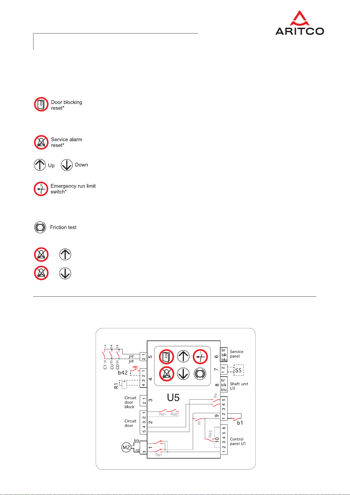
The control system is built with three kinds
of modules, i.e. the main controller (U1 module)
is placed in the cabin, U3 modules are placed
at each floor and one U5 module is connected
between the U1 and U3 modules.
The software in all modules is the same in
the 7000 series as in the 4000 and 2000
series, thus making them interchangeable.
Many features are built in by default:
•Error memory [ see page 15 ]
•Floor locking (school locking)
[ see page 8 ]
•Battery supervision [ see pages 7, 15 ]
•Emergency light supervision
[ see page 15 ]
•Automatic lubrication of screw
(adjustable) [ see page 12 ]
•Fire drive [ see page 12 ]
•Arrival signal On/Off [ see page 12 ]
•Call delay 2.5/5.0 seconds [ see page 12 ]
•Automatic cabin light off [ see page 12 ]
•Send cabin away from floor:
– Open the door, push desired floor button
inside the cabin for at least 3 seconds.
– Step outside, close the door and push the call button –
the lift will go to the floor you selected
•Backup power for emergency lowering down to the nearest floor
and keeping S3 (RM, Retiring ramp) locked when floor is school locked.
•Emergency lowering is executed by pressing any cabin destination button.
•Call buttons with error indication from the Error memory. [ see page 7 ]
•The floor indicator can display Run time and Number of starts. [ see page 13 ]
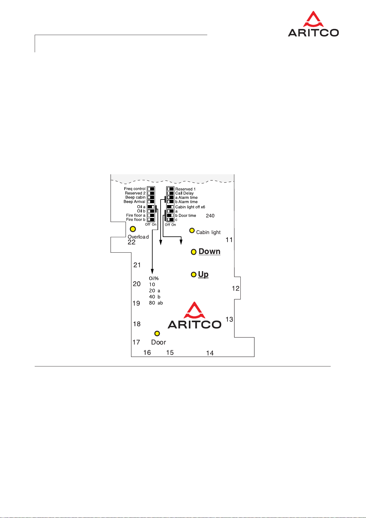
•Call button light is red or green.
Red light indicates an occupied mode and the lift will not respond.
The lift is occupied if:
– the cabin is in motion,
– a door is open
– someone using the lift has not yet reached their destination and
closed the door behind them
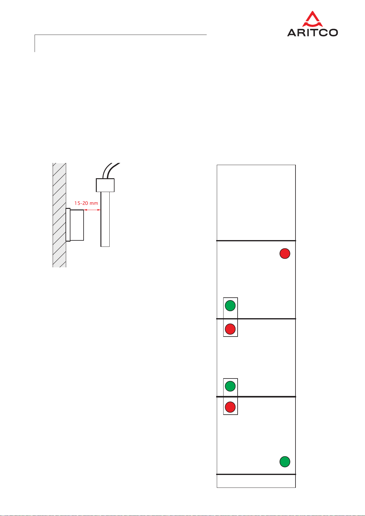
If necessary:
Reset the Lift occupied mode by pressing the Service alarm reset button

Simply platform lifts
20110609 © ARITCO 4
2 Initial test, 3-phase
In order to test that the phase sequence regarding 3-phase lifts is correct,
perform the following test from within the cabin:
1) Check that the Freq control DIP switch is in the off position.
2) Move the lift up or down from within the cabin.
3) At the same time, notice which one of the indicators UP or DOWN
lights up in the U1-module (main control).
4) If the lift is running in the same direction as indicated, then the 3-phase
sequence is correct – otherwise, change the 3-phase sequence.
3 Power down / Battery
When a Power down is required for a longer period of time,
switch off fuses E2 and E3.
Otherwise the battery will be discharged and may get damaged. The battery
supports the main system for approx. 7 hours if fully charged.
If it is necessary to change the battery, use only a Lead-Acid battery with a
capacity of 3.4
Ah.

Simply platform lifts
20110609 © ARITCO 5
4 Stop switches
The Stop switches are three bistable reed
switches: 1 (b31), X (b33) and Top (b36).
When the lift has two floors, X is not used.
The distance between magnets and switches
should be 15–20 mm (figure below).
If the distance is too short it can cause double-
click. [ see page 15 ]
The magnet positions
are shown in the figure
to the right.
4
3
2
1
X
U5
1
Top
Red
Green
Green
Red
Red
Green

Simply platform lifts
20110609 © ARITCO 6
5 Shaft modules
5.2 U5 connections
5.1 U5 Functions
Resets the Door blocking, circuit b30–b31.
A steady lit button indicates a closed curcuit. A flashing button indicates
an open circuit. Reset by pushing the button until a sound is heard (approx.
2 seconds).
Resets the Service alarm relay. If lit, see 5.4 Error alarm below.
Resets the Lift occupied mode. [ see page 3 ]
Up and Down buttons enable manual emergency override while the lift is within
the operating zone.
The Emergency run limit swich button, in combination with the Up or Down
button, makes it possible to force the lift back into the operating zone if it has
exceeded its limits, i.e. gone too far up or down. Exceeded limit is indicated by
flashing Emergency run limit button when Up or Down button is pushed.
In order to test the friction keep the Friction test button pressed down. The lift
will move down for approx. 2 seconds followed by a motor stop with open
brakes – thus leaving the cabin to stop shortly by itself due to screw friction.
You can activate a Call from another floor (above or below):
• KeeptheServicealarmresetbuttonpresseddownand
• pusheitherUporDownbutton–acallwillbemade.
* LED indicator
+
+

Simply platform lifts
20110609 © ARITCO 7
5.4 Error alarm (R1)
If an error occurs, rendering the lift out of order, an error alarm will be
activated.
When the Error alarm is activated, it lights up the “Service alarm
reset” button, pulls the output on Error relay R1 and makes all
call buttons flash green.
The Error alarm is activated if:
1 Emergency light is lit – 230
V current down
2 Battery error (Error memory 2:1–2:3)
3 Emergency alarm relay is activated
4 Friction test is activated (Error memory 3:5)
5 Photocell error; 2000 series (Error memory 4:2)
6 Contactor supervision error (Error memory 2:6)
7 24
V overcurrent (Error memory 2:4)
8 24
V overcurrent, connector 23 (Error memory 3:6)
9 Fire drive is activated (Error memory 3:4)
10 Doors are open too long (Error memory 2:5) or emergency stop
5.3 Remote service box/panel
A remote control panel (mainly 4000-series) is
connected to 6U5.6.
For funtions see 5.1 U5 Connections above.

Simply platform lifts
20110609 © ARITCO 8
Shaft modules U3 are identical and interchange-
able with each other.
Connections 3and 4are for com-
munication to and from the U3-module. It does
not matter in which order you connect them.
The U3.1-n is located above the door on each floor.
[ n = number of floors ]
The number of installed U3-modules is indicated
by the indicator lights 1–6.
If the indicated number and the actual number of
U3 modules do not match, then there is an error –
it may be a defective connection or module.
Proper, ongoing communication is indicated
by randomly flashing U5.8, U5.10 and Front panel
9 (Signal) lights.
When the U5.8, U5.10 or Front panel 9 (Signal)
light is lit continuously or off, an error is indicated.
If the indicator light 8 is lit on the U5 module,
search for the error towards the U3 modules.
If the indicator light 10 is lit on the U5 module,
search for the error towards the U1 module.
U3.1-n connections
5.5 U3 Connections

Simply platform lifts
20110609 © ARITCO 9
6 Front panel

Simply platform lifts
20110609 © ARITCO 10
7 U1-module functions
1b31 Stop switch 1
Input for stop switch on first floor.
When lift is on this floor the switch is open and
control light 1 is not lit. [ see page 5 ]
2b33 Stop switch X
Input for stop switch on intermediate floor.
When lift is on this floor the switch is open and
control light X is not lit. [ see page 5 ]
3b36 Stop switch Top
Input for stop switch on top floor.
When lift is on this floor the switch is open and
control light Top is not lit. [ see page 5 ]
4b11–b16 Cabin call
Input for cabin calls.
Button is connected between pin 7 and desired
floor.
5Communication
Input used for programming the control system.
6Alarm phone
Connector for alarm phone.
7Floor indicator U7
Connector for floor indicator.
8Contactor
Input for check of main contactors.
The control light is lit when a contactor is activ-
ated. If the indicator is lit when the lift is not
running, then a contactor is stuck or a fuse E3
is off.
If the control light is not lit when the lift is running,
an error in the Error memory will appear and the
control system will be blocked.
9Cabin cable
Connection of cabin cable 11–18.
Pins 1, 2: Emergency motor.
Pins 3–5: Power supply and signal to U3- and
U5-modules. Control light shows the
status on signal wire. It should flash
irregularly.
Pins 6–8: Phone line and alarm relay
10 H1 Cabin light
Cabin light (230 VAC) is connected here.
11 Input 230V
Connection of cabin cable 4–10.
Pins 1, 2: Connection 230VAC supply.
Pins 3, 4: Output H1 shaft light (option).
Pins 6–8: Control for main contactors.
12 S2 Battery
Connection for 24V Lead-Acid battery (Pb).
13 E2, E3 Fuse
Connection for fuses for safety chain and battery.
14 TR1 Transformer
Connector for transformer.
230V/48V/24V.
15 b8.1-n Door · b9.1-n Lock
Connection for cabin cable 1–3.

Simply platform lifts
20110609 © ARITCO 11
16 b60 Safety switch
Connector for service hatch.
17 b6 Safety switch
Connector for platform right.
18 b5 Safety switch
Connector for platform left.
19 b4 Safety switch
Connector for top left.
20 b3 Safety switch
Connector for top right.
21 b2 Safety switch
Connector for Emergency stop platform.
22 b19 Overload
Connector for overload switch.
Control light should be lit when normal.
23 b80 Cabin panel
Connector for Emergency alarm button.
Output for Overload light and Alarm control light.
Emergency telephone should be supplied
from this connector.
24 H2 Emergency light
Output for emergency light 24VDC.
25 F1 Frequency inverter
Output for control signal to frequency inverter.
26 S3 RM
Output for control of retrieving motor.
27 Photocell
Input photocell (exclusive to 2000 series).

Simply platform lifts
20110609 © ARITCO 12
8 DIP switches
In the control system there are 16 DIP switches
that allow a number of variables to be changed.
Frequency control: On = Frequency inverter
connected.
Reserved 2: Used together with Freq control.
On = Activation of B-lift function (exclusive to
2000 series).
Beep cabin: On = Audible feedback when cabin
button is pressed
Beep Arrival: On = Beep on floor arrival.
Oil: Lubrication in proportion of running time
1:off 2:off = 10 %
1:on 2:off = 20 %
1:off 2:on = 40 %
1:on 2:on = 80 %
Or at least 30 seconds each day.
Fire: Fire alarm; the lift will always go to this floor
1:off 2:off = Floor 1
1:on 2:off = Floor 2
1:off 2:on = Floor 3
1:on 2:on = Floor 4
Reserved 1: Double floor, used when a floor has
two doors and you want to separate cabin and call
button for each door.
Fire floor is set to the floor with two doors.
An extra shaft module is placed on this floor.
Fire floor and floor with two doors must be
the same floor.
Call delay:
Response time after door is closed is delayed
when lift is called from another floor.
Off = Cabin —> Floor 2.5 sec minimum
On =
Cabin —> Floor 5.0 sec minimum.
Door opening is also delayed when the lift is
called from the outside.
Alarm time: Delay for alarm relay is 3–15 sec.
If setting is “1”, there is no delay or latching of
relay.
Cabin light off: On = Cabin light goes out after
the lift has been inactive for 6 x the door time.
Door time: Door open time is 6–60 sec.
Time a b c
6 off off off
8 on off off
12 off on off
15 on on off
22 off off on
30 on off on
45 off on on
60 on on on

Simply platform lifts
20110609 © ARITCO 13
9 Floor display and statistics
9.1 Floor display and
speech
When a floor indicator with or without speech is
used, parameters need to be set up. This is done
by pressing the red RESET button on the control
system and at the same time pressing the black
buttononthecontrolsystem.Keepthempressed
until a long beep is heard (7 sec).When this is
done one of the indicators 1–6 is lit up.With the
black button you step the indicator through 1–6.
When the indicator “X” (1–6) is lit you can de-
crease parameter “X” by pressing cabin button 1
and increase it by pressing cabin button 2.
Example: Adjust the floor indicator for the first
floor. Place the lift on the first floor. Press the but-
tons on the control system so that one of 1–6 is lit.
Push the black button so that indicator 1 is lit.
Press the first and second cabin buttons to adjust
the floor indicator.When you are finished press
the red RESET button to return to normal mode.
Move the lift to another floor and repeat the setup
procedure.
Parameter table
1: Matrix
2: Speech
3: Volume
4: Language
5: “Door closing” ON or OFF
6: – –
9.2 Run time and
Operating time
The floor indicator is able to display Run time and
Number of starts.
In order to view the statistics follow the procedure
below.
• Placetheliftonthefloorwherethecontrol
system (U1) is located.
• PresstheEmergencystopbutton
• PresstheFrictiontestbutton
The floor indicator immediately displays the total
number of Starts and Operating time.
• PresstheFrictiontestbuttonagain.
The Trip counter will be displayed.
The Trip counter can be reset by
pressing the Service alarm reset button
and the Friction test button
at the same time for
approx. 3 seconds.
+

Simply platform lifts
20110609 © ARITCO 14
10 Error diagram

Simply platform lifts
20110609 © ARITCO 15
11 Error memory
The Error memory can show up to 24 errors.
Display the error by a quick push on the black
button next to the control light Err.
Reset the Error memory completely by pressing
the black button for 3 seconds. Indicated errors
are automatically reset 7 days after the latest event.
The error (one of the 24 options) is presented
by a control light (1–6) in four different groups
(level 1–4).
—————————————————————————————————
• Whenthebuttonispressedafirsttime,the
Err light is lit continuously and possible errors
1 to 6 are displayed by the control lights 1–6,
that indicate:
Level 1
————————————
1 Door or safety switch above during run
2 Lock switch during run
3 Stop switch 1 double click
4 Stop switch X double click
5 Stop switch Top double click
6 Step error
—————————————————————————————————
• Whenthebuttonispressedasecondtime
within 60 seconds, the Err light will repeat one
flash and possible errors 7 to 12 are displayed
by the control lights 1–6, that indicate:
Level 2
——
1 Battery capacity is low l
2 Battery is missing l
3 Emergency light is missing l
4 24 V overcurrent t
5 Doors are open more than 2 minutes t
6 Contactor supervision does not work t
• Whenthebuttonispressedathirdtimewithin
60 seconds, the Err light will repeat two flashes
and possible errors 13 to 18 are displayed by
the control lights 1–6, that indicate:
Level 3
————
1 Shaft module has lost connection
2 Battery test aborted, high current
3 Battery test not started, low voltage < 26V
4 Fire drive is or has been activated t
5 Brake test is or has been activated t
6 24 V is lower than 13 V and has been discon-
nected or 24 V is missing on connector 23 t
—————————————————————————————————
• Whenthebuttonispressedafourthtimewithin
60 seconds, the lit Err light will repeatedly be off
and possible errors 19 to 24 are displayed by
the control lights 1–6, that indicate:
Level 4
————— ——————
1 Photocell switch above during run
2 Photocell test stop > 3 errors t
3 Lock error (> 6 seconds)
4 Run timer timeout (> 120 seconds)
5 – –
6 – –
—————————————————————————————————
lThese errors activate the Error relay in
the U5 and will make the beeper sound
when the lift is running.
Battery capacity (2:1) and Emergency light
missing (2:3) are to be tested once a month.
The test is done by turning the emergency
light on for 2.5 hours. During this time the
voltage over the battery may not drop below
24.5 V.
t If the Err control light is flashing rapidly,
then the lift is blocked by these signals.
If it is blocked more than 30 seconds
it activates the Error realy in the U5.

Simply platform lifts
20110609 © ARITCO 16
Attachment 1
Component list 7000 series
b1 Final limit switch
b2 Emergency stop platform
b3 Stop switch platform top right
b4 Stop switch platform top left
b5 Stop switch platform floor left
b6 Stop switch platform floor right
b8 Door switch
b9 Locking switch
b10 Emergency stop shaft
b11 Cabin destination floor 1
b12 Cabin destination floor 2
b13 Cabin destination floor 3
b14 Cabin destination floor 4
b15 Cabin destination floor 5
b16 Cabin destination floor 6
b19 Overload switch
b20.1-n Call button floor
b30.1-n Door block switch (lock)
b31.1-n Door block switch (door)
b3 1 Stop switch floor 1
b33 Stop switch floor X
b36 Stop switch top floor
b40.1-n Floor lock
b42 Fire
b60 Service hatch switch
b80 Alarm button
C1 Main contactor
C10 Main contactor
C11 Main contactor
CU UP contactor
CD DOWN contactor
E1 Cabin light and control system
Fuse 230
VC, 1
A
E2 Fuse 48
VC, 0.5
A
E3 Fuse 24
V
B, 6
A
E4 Overload relay
400
V = 5.2
A
230
V = 9
A
F1 Frequency inverter
H1 Cabin/Shaft light
LED 24
V or 15
W 230
V
H2 Emergency light
LED 24
V.
H3 Alarm indicator
H4 Overload indicator
H5 Arrival indicator
M1 Lift motor 230/400
V 2.2
kW
M2 Emergency motor 24
V
Q1 Main switch
R1 Service alarm relay (error relay)
24
VDC (option)
S1 Brake
S2 Emergency battery
24
V 3.4
Ah (2 x 12
V)
S3 = RM = Retiring ramp
S4.1-n Door opener
S5 Oil valve
TR1 Transformer
T1 Emergency telephone
U1 Control system
U2 Alarm bell
U3.1-n Module
U4 Soft starter
U5 Module
Cable colours
vi = violet
or = orange
wh = white
gr = grey
blk = black
blu = blue
rd = red
br = brown
tr = transparent

Simply platform lifts
20110609 © ARITCO 17
Attachment 2
Cabin
Attachment 3
Mast
Table of contents
Other ARITCO Lifting System manuals
Popular Lifting System manuals by other brands

spanesi
spanesi MINIBENCH Operating and service manual

Tuxedo
Tuxedo TP9KACX Installation & operation manual

ReadyLift
ReadyLift 44-19620 instruction manual

Tsubaki
Tsubaki ZIP CHAIN LIFTER manual

Silverline
Silverline 865628 Original instructions

Basta Boatlifts
Basta Boatlifts Over-Center 24k60 Assembly & installation