Terberg OmniTRADE User manual

M A N U A L B I N L I F T S Y S T M
37751
Baronieweg 23
3403 NL IJsselstein
The Netherlands
Telephone: (+31) 30 2100 600
Telefax: (+31) 30 2100 610
Homepage: www.terbergmachines.nl
-mail: info@terbergmachines.nl
Omni
TRADE
Translation of the original instruction
Issue date 12-2014
The original Dutch version (article code 37750) can be obtained from Terberg.
Please send a mail to: info@terbergmachines.nl

2N
EN
Contents
37751
12-2014
ãTerberg Machines B.V., IJsselstein, The Netherlands
All rights reserved. No part of this book may be reproduced, stored in database or retrieval system, or published, in any form or in any
way, electronically, mechanically, by print, photoprint, microfilm or any other means without prior written permission from the publisher.
Page Page
OREWORD
•General 3
•Guarantee 3
•Operator requirements 3
•Description of sections 3
•Symbols used 3
1. INTRODUCTION
1.1 Description of the bin lift system 4
1.2 Technical specifications 5
Bin/container and bin lift information 5
2. SA ETY
2.1 General safety instructions 6
2.2 Safety instructions
During use of the bin lift system 7
During maintenance and repair 7
2.3 Warning signs 8
2.4 Safety features: Emergency stop 9
3. BIN LI T OPERATION
3.1 Important components 10
3.2 Warnings and tips 11
3.3 Daily checks 11
3.4 Loading bags and/or bulky waste 12
3.5 Loading via the pick-up comb
2-Wheel bins 13
4-Wheel containers 14
3.5.1 SMT: One man operation 15
3.6 Loading with pick-up arms (option) 16
3.7 Travel height and footboards 17
4. MAINTENANCE AND CLEANING
4.1 General and daily maintenance 18
4.2 Weekly maintenance 18
4.3 Six-weekly maintenance 19
4.4 Annual maintenance 20
4.5 Maintenance schedule 22
4.6 Troubleshooting 23
4.7 ault blink code diagnosis 24
4.8 Opening the hydraulic system 25
5. DIMENSIONS
5.1 Bin lift 26
5.2 Required dimensions of compactor body 27
6. INSTALLATION
6.1 Installation on the body (with frame) 28
6.2 Installation on the body (without frame) 29
6.3 ootboards: Installation advice 30
6.4 Hydraulic connection 31
6.5 Electrical connection 31
7. HYDRAULICS
7.1 Hydraulic connections and components 34
8. ELECTRICAL
8.1 Electrical connections and
components P&P diagram 37
8.2 Electrical diagram 38
9. DECOMMISSIONING (disposing) 40
PARTS BOOK 101

N 3
EN
37751
12-2014
oreword
ãTerberg Machines B.V., IJsselstein, The Netherlands
All rights reserved. No part of this book may be reproduced, stored in database or retrieval system, or published, in any form or in any
way, electronically, mechanically, by print, photoprint, microfilm or any other means without prior written permission from the publisher.
oreword
This user manual provides information about the
operation and maintenance of the Omni
TRADE
bin
lift system.
In order to work safely and efficiently with this man-
ual bin lift system, it is essential that you read this
manual carefully before putting the bin lift into use.
Make the user manual available to everyone con-
cerned with the operation and/or the maintenance
of the bin lift.
Consult the user manual as needed for the truck
chassis and the packer.
When all the operating and maintenance instructions
have been met the bin lift can be safely used.
Should you nonetheless have any further questions,
please get in touch with your distributor.
Guarantee
For more information about the conditions of guar-
antee, please contact your distributor.
Operator requirements
- The bin lift system may only be operated by per-
sons who are familiar with the operation of the bin
lift.
- Repairs may only be carried out by qualified per-
sonnel.
Symbols used
Note:
Additional information.
Warning:
If these instructions are not followed, there
is a risk of damage to the equipment
and/or personal injury.
Stop:
If these instructions are not followed cor-
rectly, there is a risk of personal injury
and/or risk of serious damage to the equip-
ment.
The user manual has the following sections:
Introduction
A description of the function, conditions of use and
the operating principle of the machine.
Safety
Description of the safety provisions and the mea-
sures that need to be taken into account in order to
work safely with the machine. As well as an explana-
tion of the symbols on the machine.
Operation
A clear description of the most important compo-
nents and instructions for emptying different types of
bin.
Maintenance and cleaning
Covers all the periodic operations needed for the
correct functioning of the machine, trouble shooting
and fault diagnosis.
Dimensions
Dimensions for bin lift, centre of gravity and required
dimensions for the compactor body.
Installation and putting into service
A description of the installation and the mounting
dimensions of the machine. In addition, a summary of
the resources and tools required.
Technical information
Hydraulic connections and components, electrical
connections and components P&P and parts.
Decommissioning
Description of the steps needed for the safe disas-
sembly and environmentally friendly processing of
the machine.

07
09
08
06
10 11
12
05
11
10
S
T
O
P
S
T
O
P
03
04
4N
EN
1. Introduction
37751
12-2014
1.1
Description of the bin lift system
The Omni
TRADE
is a manually-operated bin lift sys-
tem that can be deployed for a wide range of uses.
It is not only suitable for emptying the commonly
used 2-wheel bins but also most of the 4-wheel con-
tainers.
The various (optional) pick-up arms allow even con-
tainers without a comb receiver pick-up edge to be
emptied.
The Omni RADE can be supplied with an integral
mounting frame (available in widths of 2.2 and 2.5
metres).
There is a button control station (03) on the L/H side
tilt arm, with which the container can be partly lifted,
with the rest of the cycle being completed using the
standard control station on the L/H or R/H side.
ãTerberg Machines B.V., IJsselstein, The Netherlands
All rights reserved. No part of this book may be reproduced, stored in database or retrieval system, or published, in any form or in any
way, electronically, mechanically, by print, photoprint, microfilm or any other means without prior written permission from the publisher.
01/02= Button control station right/left
A second control station is an option.
03 = Button control station for container take-up
04 = Emergency stop
05 = Pick-up comb
06 = Hopper plate
07 = Catcherbar, 2-wheel bins and 4-wheel containers
(500-770 litres with flat lid)
08 = Container stop, 4-wheel containers
(1000-1280 litres & Paladin / Chamberlain)
09 = Lid opener
10 = Bin guide plate
11 = Start sensors
12 = Sensor for 4-wheel containers
Pick-up arms may also
be fitted as an option.
A B
02
A B
01

N 5
EN
37751
12-2014
1. Introduction
1.2
Technical specifications
ãTerberg Machines B.V., IJsselstein, The Netherlands
All rights reserved. No part of this book may be reproduced, stored in database or retrieval system, or published, in any form or in any
way, electronically, mechanically, by print, photoprint, microfilm or any other means without prior written permission from the publisher.
Directives and Standards 2006/42/ G, N 1501-1 & N 1501-5: 2011
Sound pressure 65 dB(A)
Vibration 2.5 m/s2
Operating voltage 24 Volts DC
Current 10 Ampère / 24V DC
Oil flow 30-60 litre/minute
Working pressure compactor body Min. 190 bar / Max. 250 bar
Return pressure: Max. 2.0 bar
2-wheel bins 4-wheel containers
with flat lid
4-wheel containers
with roll top
Chamberlain /
Paladin containers
Capacity (litres) 80 - 390 500 - 770
1000 - 1280 770 - 1100 900
According to standard EN 840-1 EN 840-2 EN 840-3 --
Lifting capacity 1600 N (160 kg) 7500 N (750 kg)
Cycle time ±11.5 seconds ±10 seconds
Emptying time adjustable
Automatic emptying no no no no
Manual emptying yes yes yes yes
Pick-up via comb yes yes yes yes
Pick-up arms not applicable (optional) (optional) not applicable
Lid opener not applicable not applicable yes not applicable
Bin stop / catcherbar position A
(working position)
500-770: position A
(working position)
1000-1280: position B
(folded-away)
position B
(folded-away)
position B
(folded-away)
Bin/container and bin lift information
Chamberlain
he emptying of bin/container types other than
those indicated above, is not permitted with
this bin lift system.
If in doubt, please contact your distributor.
Weights
Bin lift (without lid opener, mounting frame, pick-up arms, footboards) 521 kg
Bin lift weighing (without lid opener, mounting frame, pick-up arms, footboards) 588 kg
Bin lift with DIN pick-up arms (without lid opener, mounting frame, footboards) 552 kg
Lid opener, catcherbar assembly [ref. fig. 5 in partsbook] 56 kg
Mounting frame 2.5m (30188) [ref. fig. 6 in partsbook] 154 kg
Mounting frame 2.5m small (38070) [ref. fig. 6 in partsbook] 54 kg
Hopper beam 2.5m (38156) [ref. fig. 2 in partsbook] 22.5 kg

•If the safety features are damaged, they must be
immediately repaired or replaced by original parts.
•The movement speeds and lifting forces set by the
manufacturer may on no condition be altered.
•Operating and safety decals should be present and
clearly legible.
•Actions that override the safety provisions are
expressly forbidden!
•Reversing is only permitted when the lifting chairs
are at a safe height.
•It is forbidden to stand on the footboards while
the refuse collection vehicle is reversing.
•Take care that during reversing you are visible to
the driver of the refuse collection vehicle.
•The bin lift may never be used as a hoisting instru-
ment.
•No vehicle may be towed with the towing cable
attached to the bin lift system.
•The refuse collection vehicle may never be lifted
by the lifting points of the bin lift.
•The pick-up arms should be folded in while the
vehicle is in motion.
•When riding on the vehicle you must absolutely
not sit or stand on parts of the machine other
than the special footboards for this purpose,
this
really is extremely dangerous!
•In extremely bad weather (storms, thunder-
storms, etc.) it is not advisable to use the bin lift
system.
6N
EN
2. Safety
37751
12-2014
2.1
General safety instructions
ãTerberg Machines B.V., IJsselstein, The Netherlands
All rights reserved. No part of this book may be reproduced, stored in database or retrieval system, or published, in any form or in any
way, electronically, mechanically, by print, photoprint, microfilm or any other means without prior written permission from the publisher.
General
•The bin lift system may never be operated when
the refuse collection vehicle is travelling along and
also not with reverse gear engaged.
•The bin lift system may only be operated by per-
sons who have received operator training and are
fully familiar with its operation.
•First read the operating instructions before you
start using the bin lift.
•Read through the operating instructions for the
compactor body carefully.
•In your daily work as bin lift operative you are work-
ing in traffic, do not put it or yourself in danger.
•Before starting the collection round, discuss with
your colleagues how to act in certain situations
such as stopping, driving off, etc.
•When you are working with the bin lift, you
should not wear any loose clothing and jewellery.
•While working always wear work clothing, safety
footwear and work gloves that comply with the
standards indicated in the table below.
•Make sure that an unattended bin lift can never be
put into operation by unauthorised persons
(remove the ignition key).
•Do not use the bin lift system in spaces or installa-
tions where the presence of gasses and/or flam-
mable materials creates a danger of fire or explo-
sion.
•The bin lift system may under no circumstances
be used if the oil feed rate is higher than 60 litres
per minute.
•Technical faults should be reported immediately to
the person responsible for supervising the loading.
The bin lift must be taken out of operation until
the fault (if this could present a danger) is reme-
died.
•Never use the pick-up arms or any other part of
the bin lift system as a seat.
This is life-threateningly dangerous!
•The controls may under no circumstances be
altered.
•None of the installed safety features may be
removed or altered.
Personal protection
equipment: According to standard:
Work clothing N N- N-ISO 20471:2013
Safety footwear N N- N-ISO 20345:2011
Work gloves N N- N 420:2003+A1:2009

N 7
EN
37751
12-2014
2. Safety
2.2
Safety instructions applicable during operation, maintenance and repair
ãTerberg Machines B.V., IJsselstein, The Netherlands
All rights reserved. No part of this book may be reproduced, stored in database or retrieval system, or published, in any form or in any
way, electronically, mechanically, by print, photoprint, microfilm or any other means without prior written permission from the publisher.
During the operation of the bin lift system
•nsure that no-one is in the immediate vicinity of
the bin lift system during the loading cycle.
•If the bin lift system is in operation, you may under
no circumstances reach into the lifting system
(danger of injury).
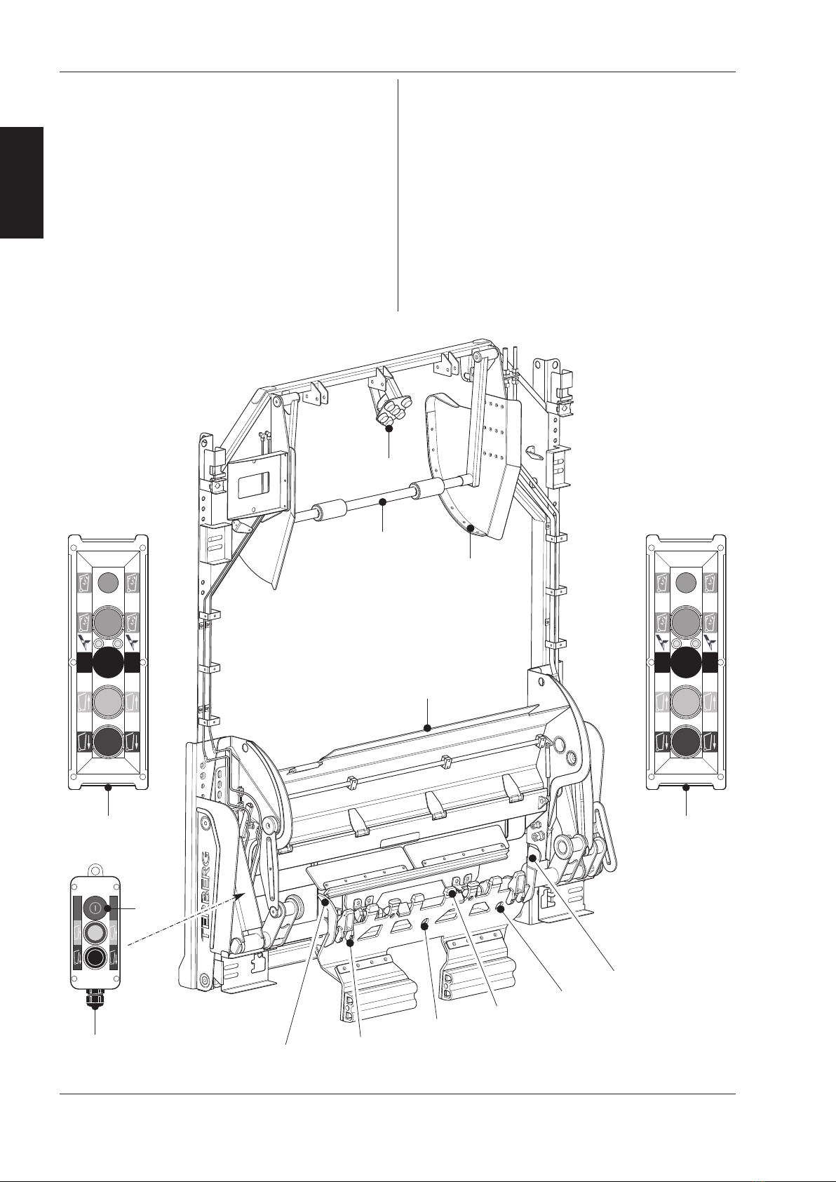
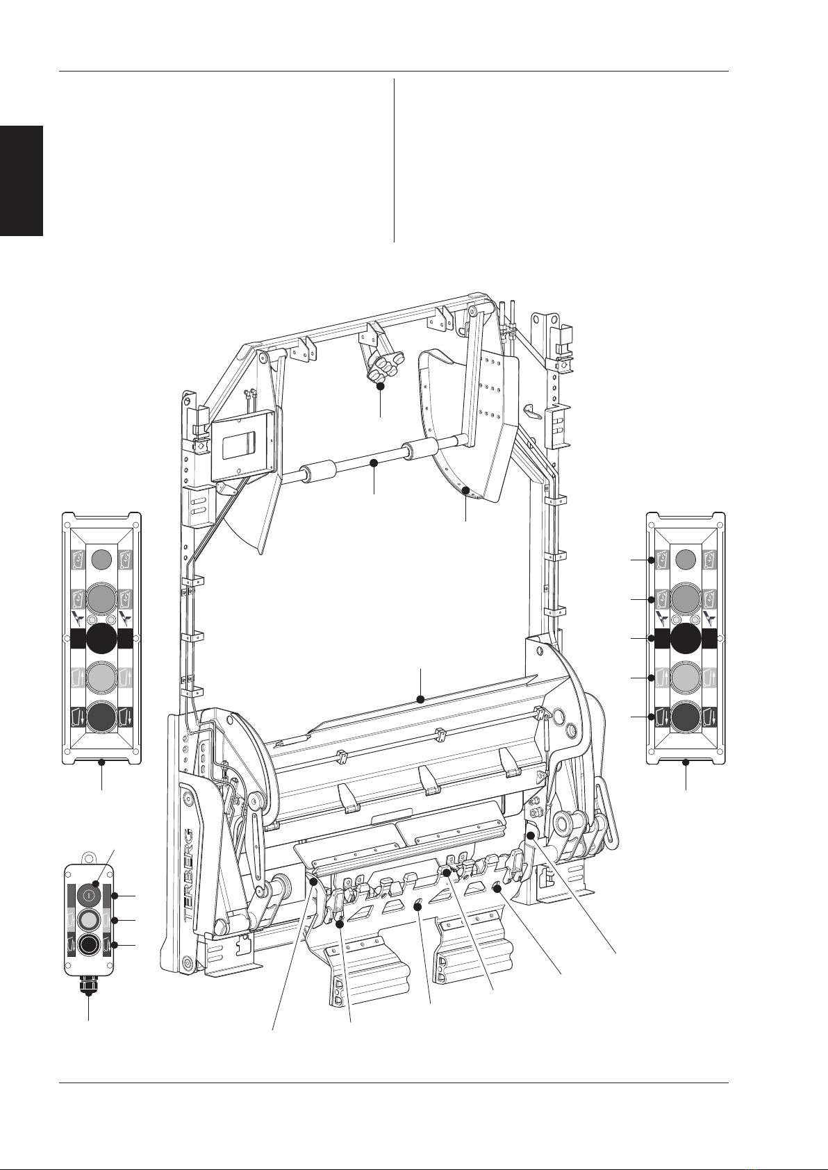
•In case of danger immediately press the closest
emergency stop switch
(see section Safety equipment 2.4).
•Check that there are no foreign objects in or
between the bin lift system that can hinder its
operation.
•Loose refuse may not be loaded above the edge
of the hopper.
•The compactor may not be used while objects are
protruding from the throw-in hole.
•Never use the bin lift system when the view of the
load is obstructed.
•Never use the bin lift system on a very uneven
surface.
•The bin lift system may not be driven up against a
bin/container or a pile of refuse.
•Take account of the heating of the hydraulic oil.
This can become 40°C warmer than the environ-
ment. As a result, the pipes and hoses can cause
light burns at high ambient temperatures.
•It is not permitted to use bin/container types not
listed in the manual.
•Nothing should protrude from the bin and only
bins whose lids are fully closed should be emptied.
•Do not empty any damaged bins. These can cause
problems.
•Overweight bins/containers should be removed
from the bin lift system:
max. lifting force 2-wheel bins: 1600N (160kg)
max. lifting force 4-wiel containers: 7500N (750kg)
•Check that the container is located correctly on
the pick-up comb or pick-up arms before you
empty it.
•Let go of the bin as soon as it is picked up by the
bin lift system.
•It is expressly forbidden to manually ‘help’ the lift-
ing system.
•Only give an extra shake if this is needed.
•Only remove the bin/container when the bin lift
system has come to rest and the bin/container is
back on the ground.
•Place empty bins/containers where they do not
pose a danger to other road users.
•It is forbidden to empty bins/containers that con-
tain dangerous and/or radioactive substances.
•It is not permitted to empty bins/containers that
contain burning or smouldering materials.
•Never walk backwards towards the bin lift system.
•One person offering and/or taking several bins at
the same time must be kept to a minimum.
•A bin may only be offered to the bin lift system
when held by the handle bars.
•During winter conditions, if the bin lift is contami-
nated by heavy snow or ice deposition on mecha-
nical parts or various sensors, the system can get
clogged up. Apply stop switch prior to cleaning.
Clean these parts and keep as dry as possible. For
example with a broom. Never clean the bin lift
using defrosting liquids!
During maintenance and repair
•Maintenance and repairs may only be carried out
by authorised technical personnel.
•Any faults detected should be corrected before
the bin lift system is used.
•For maintenance and repairs switch the bin lift sys-
tem off (switch off the engine of the refuse col-
lection vehicle and turn off the main power
switch).
•During repair work, accidental activation should
be prevented by removing the ignition key from
the ignition switch (keep on your person).
•You may not go under the tilt frame for repair or
cleaning unless the tilt frame is adequately sup-
ported.
•Before cleaning can begin, you should switch off
the drive gear of the refuse collection vehicle.
•The grease between the pivots may get washed
away if you use a high pressure cleaner. Think about
the safety of your eyes and use safety glasses.
•Use the lifting points present for raising the bin lift.
•When working on the hydraulic system, you should
bear in mind that this is filled with hydraulic fluid
under pressure. Always use personal protective
equipment to avoid contact with skin and eyes. Use
absorbents to avoid environmental pollution.
Keep a minimum distance of 2.5 meter
between the bin lift and objects which are
located behind the bin lift system. his is to
avoid a dangerous situation in case that a bin
comes loose.

Warning signs
All safety and instruction decals affixed must be
replaced if damaged.
The pictogram decals have the following meanings:
Do not stand under the tilt frame!
Do not stand in working area!
Do not reach into the bin lift, danger of
injury!
8N
EN
2. Safety
37751
12-2014
2.2
Safety instructions
(continued)
ãTerberg Machines B.V., IJsselstein, The Netherlands
All rights reserved. No part of this book may be reproduced, stored in database or retrieval system, or published, in any form or in any
way, electronically, mechanically, by print, photoprint, microfilm or any other means without prior written permission from the publisher.
•You must comply with the maintenance interval
specified by the manufacturer.
•lectrical fuses should never be bridged or
replaced by a fuse with a higher power rating.
•When dismantling, disconnect the plugs and
couplings from the vehicle.
•Following a collision involving the bin lift system
Terberg will need to assess whether it is still safe
to use or first needs to be repaired.
•Original or specified parts should always be used
for repair or maintenance.
•Do not stand under the bin lift or the
bin/container!
2.3
Warning signs
Repairs may only be carried out by qualified
personnel, never rectify faults yourself, this
may cause danger for you and damage to the
bin lift system!

N 9
EN
37751
12-2014
2. Safety
2.4
Safety provisions: Emergency stop button
ãTerberg Machines B.V., IJsselstein, The Netherlands
All rights reserved. No part of this book may be reproduced, stored in database or retrieval system, or published, in any form or in any
way, electronically, mechanically, by print, photoprint, microfilm or any other means without prior written permission from the publisher.
General
•If it is noticed that the bin lift system does not
work or has a fault while collecting refuse, the
workshop or service station must be informed
immediately with a clear description of the defect.
Emergency stop button
In case of emergency, you can use the emergency
stop button (positioned on the L/H tilt arm of the
bin lift) to immediately stop the compactor and the
loading cycle of the bin lift.
mergency stop button identifier.
•After the red emer-
gency stop button is
pressed, the supply of
hydraulic oil stops and
the electrical circuit is
interrupted
•The check lights go out.
The driver of the refuse
collection vehicle is aler-
ted by a buzzer in the
cabin that the emergen-
cy stop button has been
pressed.
Reset emergency stop button
•Reset the emergency
stop button by pulling
it out. The buzzer in
the cabin stops.
•Resetting of the com-
pactor body may be
required, consult body
manual for correct
procedure.
A B
•Press the dark blue
DOWN button. The
lifting chair descends
to the lowest position.
•Solve the reason for
pressing the emergen-
cy stop button.
•Remove the bin/con-
tainer from the bin lift
system if applicable.
•
The bin lift system is ready for use again.
Entrapment
In the event of a dangerous occurance or if a person
has become trapped in the lifting mechanism and
consequently the emergency stop button has been
pressed.
The system will need to be reset to allow the lif-
ting chair to be raised or lowered which ever is
appropriate to release the person.
An understanding of the resetting procedure of the
compactor body will be required of the operators.
In such cases, proceed as follows:
•Reset the emergency
stop button by pulling
it out. The buzzer in
the cabin stops.
•Press the dark blue
DOWN button to
allow the lifting chair
to lower or the light
blue UP button to
allow the lifting chair
to raise.
A B
Repairs may only be carried out by qualified
personnel, never rectify faults yourself, this
may cause danger for you and damage to the
bin lift system!
A B

10 N
EN
3. Bin lift operation
37751
12-2014
ãTerberg Machines B.V., IJsselstein, The Netherlands
All rights reserved. No part of this book may be reproduced, stored in database or retrieval system, or published, in any form or in any
way, electronically, mechanically, by print, photoprint, microfilm or any other means without prior written permission from the publisher.
3.1
Important components
01/02= Button control station right/left
A second control station is an option.
03 = Button control station for container take-up
04 = Emergency stop
05 = Pick-up comb
06 = Hopper plate
07 = Catcherbar, 2-wheel bins and 4-wheel containers
(500-770 litres with flat lid)
08 = Container stop, 4-wheel containers
(1000-1280 litres & Paladin / Chamberlain)
09 = Lid opener
10 = Bin guide plate
11 = Start sensors
12 = Sensor for 4-wheel containers
07
09
08
06
10 11
12
05
11
10
A B
S
T
O
P
S
T
O
P
02
03
A B
01
G
F
H
E
D
C
A
B
04
A B
S
T
O
P
S
T
O
P
02
03
A B
01
G
F
H
E
D
C
A
B
04
A B
S
T
O
P
S
T
O
P
02
03
A B
01
G
F
H
E
D
C
A
B
04
A=Light blue push button UP
B=Dark blue push button DOWN
C= Push button catcherbar (with LED indicators)
D= Green push button SMT (Single-man trade
4-wheel containers)
E=Green SMT check light
=Emergency stop button
G= Push button TAKE-UP container
H= Push button DOWN

N 11
EN
37751
12-2014
3. Bin lift operation
3.2
Warnings and tips
3.3
Daily checks
ãTerberg Machines B.V., IJsselstein, The Netherlands
All rights reserved. No part of this book may be reproduced, stored in database or retrieval system, or published, in any form or in any
way, electronically, mechanically, by print, photoprint, microfilm or any other means without prior written permission from the publisher.
•It is expressly prohibited to help the bin lift system
‘manually’ with lifting.
•Lifting capacity 2-wheel bins: max. 160 kg.
Lifting capacity 4-wheel containers: max. 750 kg.
•xcessively heavy bins/containers must not be
lifted.
•Do not remove the bin/container before the bin
lift has come to a standstill.
•Always approach the bin lift forwards with out-
stretched arms, even when removing the bin/con-
tainer.
•When you are working you are in traffic; do not
put it and yourself in danger. Place empty
bins/containers where they do not cause any dan-
ger to other road users.
•When you are working with the bin lift system, do
not wear loose clothing and jewellery.
•Loading is teamwork. Before starting the collec-
tion round, discuss with your colleagues how to
act in certain situations such as stopping, driving
off, etc.
•Never use the bin lift system as a seat.
This is life-
threateningly dangerous.
•When the bin lift system is in operation, you may
not reach into the lifting system, this may cause a
danger of injury.
•It is forbidden to stand on the footboards while
the refuse collection vehicle is reversing.
•Take care that during reversing you are visible to
the driver of the refuse collection vehicle.
Before you start work, you must check the bin lift
system for the following points:
•Check that no oil loss has occurred.
•Look to see if there are any foreign objects
(branches, twigs, plastic bags, etc) in the bin lift sys-
tem that could hinder its operation.
•Operation of the controls
Check the operation of all the controls by per-
forming all the possible actions with empty
bins/containers (for information about catcherbar
position / container type, see Section 1):
- mergency stop button
- Catcherbar setting: put the catcherbar in
Position A (working position) and in Position B.
- Hopper plate operation / locking.
- Start sensors and 4-wheel recognition sensor.
•Working footboards (option)
Check the operation and mounting of the foot-
boards.
Before starting to use the bin lift system, first
read the operating instructions.

12 N
EN
3. Bin lift operation
37751
12-2014
3.4
Loading bags and/or bulky waste
ãTerberg Machines B.V., IJsselstein, The Netherlands
All rights reserved. No part of this book may be reproduced, stored in database or retrieval system, or published, in any form or in any
way, electronically, mechanically, by print, photoprint, microfilm or any other means without prior written permission from the publisher.
To make it easier to throw in bags and/or bulky
waste, you can lower the throw-in height of the bin
lift
1) Put the bin lift in the lower position before
opening the hopper plate.
2) Hopper plate (06)
Unlock the hopper plate, press down handle A
on the L/H side. Simultaneously, rotate the hop-
per plate all the way down.
A
A
hrow in long items sideways.
Do not use the bin lift as a breaking edge.
Incorrect use may damage the bin lift.
Do not forget to raise the hopper plate again
before collecting bins.

Shake function (compostable waste)
If refuse gets stick in the bin, you can use the shake
function.
Proceed as follows:
Keep the light blue UP
button (A) pressed once
the bin is in the tilting
position.
The bin is automatically
shaken 5 times.
Button control station for bin take-up (03)
On the L/H tilt arm there is a button control station
for limited raising and lowering of the pick-up comb.
•Roll the bin against / above pick-up comb (05).
•Bin take-up:
Press the UP button (G)
of the bin take-up con-
trol station (03).
The bin is picked up from
the ground with the
wheels.
Then go to the button control station (01/02) on
the L/H or R/H side.
•Then proceed as described in points 6 and 7.
N 13
EN
37751
12-2014
3. Bin lift operation
3.5
Loading with the pick-up comb
ãTerberg Machines B.V., IJsselstein, The Netherlands
All rights reserved. No part of this book may be reproduced, stored in database or retrieval system, or published, in any form or in any
way, electronically, mechanically, by print, photoprint, microfilm or any other means without prior written permission from the publisher.
1) Check that the hopper plate (06) is closed.
2) Switch on the refuse collection vehicle compac-
tor system.
3) If there are footboards, fold both of them
down.
4) Catcherbar (07):
Check that the catcher-
bar is in Position A (this
is the working position).
The yellow indicator L D
(left) should be on. If this
is not the case, press the
black button (C) once.
Alternately, the bin lift can be provided with a func-
tion that sends the catcherbar automatically to
Position A when presented with a mini-container.
5) Roll the bin against / above pick-up comb (05).
6) Bin emptying:
Press the light blue UP
button (A), on either
side of the bin lift. The
bin is then raised to the
tilting position and emp-
tied.
7) Bin removal:
Press the dark blue
DOWN button (B). The
bin then lowers back to
the ground.
Remove the bin from the
bin lift as soon as the
wheels touch the
ground.
2-wheel bins;
contents 80 to 390 litres
according to EN 840-1
Chamberlain Chamberlain
A B
A B
A B
A B
S
T
O
P
S
T
O
P
Make sure that the bin is located correctly on
the pick-up comb.
Make sure that the bin is located correctly on
the pick-up comb.
Only give an extra shake if there is a need for
this. Shaking takes time and causes extra
noise for the surrounding area.

14 N
EN
3. Bin lift operation
37751
12-2014
3.5
Loading with the pick-up comb
ãTerberg Machines B.V., IJsselstein, The Netherlands
All rights reserved. No part of this book may be reproduced, stored in database or retrieval system, or published, in any form or in any
way, electronically, mechanically, by print, photoprint, microfilm or any other means without prior written permission from the publisher.
4-wheel containers
with a ROLL top;
contents 770-1100 litres
with a LAT lid;
contents 500 to 1280 litres
The bin lift is equipped with automatic 4-wheel con-
tainer recognition. When a 4-wheel container is rol-
led against the pick-up comb, the catcherbar goes
automatically to Position B (folded-away position).
1) Check that the hopper plate (06) is closed.
2) Switch on the refuse collection vehicle compac-
tor system.
3) If there are footboards, fold both of them
down.
4) Catcherbar (07):
•For containers with a flat lid of 500 to 770 lit-
res, the catcherbar should be in Position A (this
is the working position). The yellow indicator
L D, left, should be on.
•For flat-lid containers with a capacity of 1000 to
1280 litres and for roll-top containers, the
catcherbar should be in Position B (folded-
away position). The yellow indicator L D, right,
should be on.
Put the catcherbar in the correct position using
the black button (C).
5) Roll the container against / above pick-up comb (05).
6) Container emptying:
Press the light blue UP
button (A), on either
side of the bin lift. The
container is then raised
to the tilting position and
emptied.
A B
A B
7) Container removal:
Press the dark blue
DOWN button (B). The
container then lowers
back to the ground.
Remove the container
from the bin lift as soon
as the wheels touch the
ground.
Shake function (compostable waste)
If refuse gets stick in the container, you can use the
shake function.
See 2-wheel bins, Page 13.
Button control station for container take-up (03)
On the L/H tilt arm there is a button control station
for limited raising and lowering of the pick-up comb.
•Roll the container against / above pick-up comb (05).
•Container take-up:
Press the UP button (G)
of the container take-up
control station (03).
The container is picked
up from the ground with
the wheels.
Then go to the button control station (01/02) on
the L/H or R/H side.
•Then proceed as described in points 6 and 7.
A B
A B
S
T
O
P
S
T
O
P
Make sure that the container is located cor-
rectly on the pick-up comb.
Make sure that the container is located cor-
rectly on the pick-up comb.

N 15
EN
37751
12-2014
3. Bin lift operation
3.5.1
SMT: Single Man Trade
(pick-up comb)
ãTerberg Machines B.V., IJsselstein, The Netherlands
All rights reserved. No part of this book may be reproduced, stored in database or retrieval system, or published, in any form or in any
way, electronically, mechanically, by print, photoprint, microfilm or any other means without prior written permission from the publisher.
Single man trade is a (semi-) automatic function that
makes it possible for one person to empty 4-wheel
containers or multiple 2-wheel bins.
1) Any pick-up arms should be folded in.
2) Check that the hopper plate (06) is closed.
3) Engage SMT:
Press the green SMT
button (D), the green
indicator light (E) comes
on.
4a) 4-Wheel containers:
•Roll the container against and above the pick-
up comb. The container is automatically lifted
by about 20 cm.
•The bin lift now waits until an UP/DOWN
button on the L/H or R/H control station is
activated.
•Then proceed as described in points 4 to 7
on the page to the left, except for Point 5.
4b) 2-Wheel bins:
•Roll a bin left or right against and above the
pick-up comb.
he bin lift will wait a few seconds to see if a
second bin is rolled next to it. If this does not hap-
pen, the bin, after this time-out, is automatically
lifted by about 20 cm.
•If a second bin is presented, both bins will be
automatically raised.
•The bin lift now waits until an UP/DOWN
button on the L/H or R/H control station is
activated.
•Then proceed as described in points 4 to 7
on the page to the left, except for Point 5.
A B
Make sure that the bin/container is located
correctly on the pick-up comb.
One-man operation is only possible when
4-wheel containers are lifted with the pick-up
comb.

The Omni
TRADE
can (optionally) be fitted with
pick-up arms.
1) Check that the hopper plate (06) is closed.
2) Switch on the refuse collection vehicle compac-
tor system.
3) If there are footboards, fold both of them down.
4) old out both pick-up arms.
5) Catcherbar (07):
•For containers with a flat lid of 500 to 770 lit-
res, the catcherbar should be in Position A (this
is the working position). The yellow indicator
L D, left, should be on.
•For flat-lid containers with a capacity of 1000 to
1280 litres and for roll-top containers, the
catcherbar should be in Position B (folded-
away position). The yellow indicator L D, right,
should be on.
Put the catcherbar in the correct position using
the black button (C).
6) Roll the container straight between the pick-up
arms.
7) Bring the pick-up heads to the correct height:
Use the light blue UP
button (A) to raise both
pick-up arms until the
pick-up heads are level
with the trunnions of the
container.
8) Container emptying:
Press the light blue UP
button (A), on either
side of the bin lift. The
container is then raised
to the tilting position and
emptied.
9) Container removal:
Press the dark blue
DOWN button (B). The
container then lowers
back to the ground.
Make sure the trunnions
of the container come
out of the pick-up heads
of the pick-up arms.
Roll the container out of
the bin lift.
Trunnions stuck in pick-up heads.
In this case, proceed as follows:
•Raise the container slightly using the light blue UP
button (A) until the wheels are free of the ground.
•Pull the container backwards so that the trunnions
of the container are in the lower position of the
pick-up heads.
•Then let the container descend.
16 N
EN
3. Bin lift operation
37751
12-2014
3.6
Loading with pick-up arms
(option)
ãTerberg Machines B.V., IJsselstein, The Netherlands
All rights reserved. No part of this book may be reproduced, stored in database or retrieval system, or published, in any form or in any
way, electronically, mechanically, by print, photoprint, microfilm or any other means without prior written permission from the publisher.
4-wheel containers
with a ROLL top;
contents 770-1100 litres
with a LAT lid;
contents 500 to 1280 litres
A B
A B
A B
A B
A B
When the pick-up arms are used, SM (Single
man operation of 4-wheeled containers) is no
longer possible.
ake great care that the container’s trunnions
insert firmly into both pick-up heads of the
pick-up arms.
On an uneven road surface the trunnions of
the container may get stuck in the top position
of the pick-up heads.
Ensure that your fingers do not become
trapped when folding in the pick-up arms.

N 17
EN
37751
12-2014
3. Bin lift operation
3.7
Travel height and footboards
ãTerberg Machines B.V., IJsselstein, The Netherlands
All rights reserved. No part of this book may be reproduced, stored in database or retrieval system, or published, in any form or in any
way, electronically, mechanically, by print, photoprint, microfilm or any other means without prior written permission from the publisher.
Throwing waste in manually
Throw large heavy objects across the width of the
compactor space to prevent damage to the bin lift
system.
Obstacles or uneven surfaces
When driving over large obstacles or uneven terrain,
it is important to place the footboards in the trans-
port position and tilt the bin lift up for adequate
ground clearance.
ootboards and handle bars
As an option the bin lift system can be fitted with
footboards and handle bars. The handle bars - two
brackets on either side - are fixed.
These are used in three situations. In each of these
situations, the footboards must be in the correct
position.
1) Transport
Footboards folded up.
2) Loading
Footboards folded down.
3) Riding
Footboards folded down.
If someone is standing on the footboard:
•Reversing is not permitted.
•The refuse collection vehicle may not be driven at
more than 30 kilometres per hour (19 mph).
•The compactor should not run in full automatic
mode.
Transport
Hand-
positions
B
A
Loading Riding
he bin lift may never be operated when the
refuse collection vehicle is travelling along and
also not when reverse gear is engaged.
Never stand on other parts of the bin lift and
also never use them as a seat,
this is
extremely dangerous!
Table of contents
Other Terberg Lifting System manuals
Popular Lifting System manuals by other brands

REID LIFTING
REID LIFTING PORTA-DAVIT 500 Series Assembly & operation

SVERO
SVERO 7112A manual

Patriot Docks
Patriot Docks PN10474 quick start guide

MAHA
MAHA MPL 3.5 operating instructions

Pressalit Care
Pressalit Care SELECT R9014 Mounting instruction

Leggett & Platt
Leggett & Platt Adjustable Base Setup guide