Arjo Typhoon Instruction manual

ASSEMBLY AND INSTALLATION INSTRUCTIONS
Typhoon
06.TY.00_1EN • 11/2019

The model name and serial number should always be provided when ordering
spare parts or during queries per telephone or written correspondence:
Serial number of the machine:
……………………………………………………
Machine model:
……………………………………………………
Design Policy and Copyright
® and ™ are trademarks belonging to the Arjo group of companies.
© Arjo 2019.
As our policy is one of continuous improvement, we reserve the right to modify designs without prior
notice. The content of this publication may not be copied either whole or in part without the consent of
Arjo.

3
Contents
PREFACE............................................................................................................................4
1 SAFETY PRECAUTIONS..............................................................................................5
1.1 Important..............................................................................................................6
1.2 Make sure assembly and installation work is carried out by................................7
1.3 Isolator switch......................................................................................................7
1.4 In an emergency..................................................................................................7
1.5 Product liability.....................................................................................................7
1.6 Attention symbols.................................................................................................7
2 INSTALLATION..............................................................................................................8
2.1 General................................................................................................................8
2.1.1 Make sure assembly and installation work is carried out......................8
2.1.2 Installation order ...................................................................................8
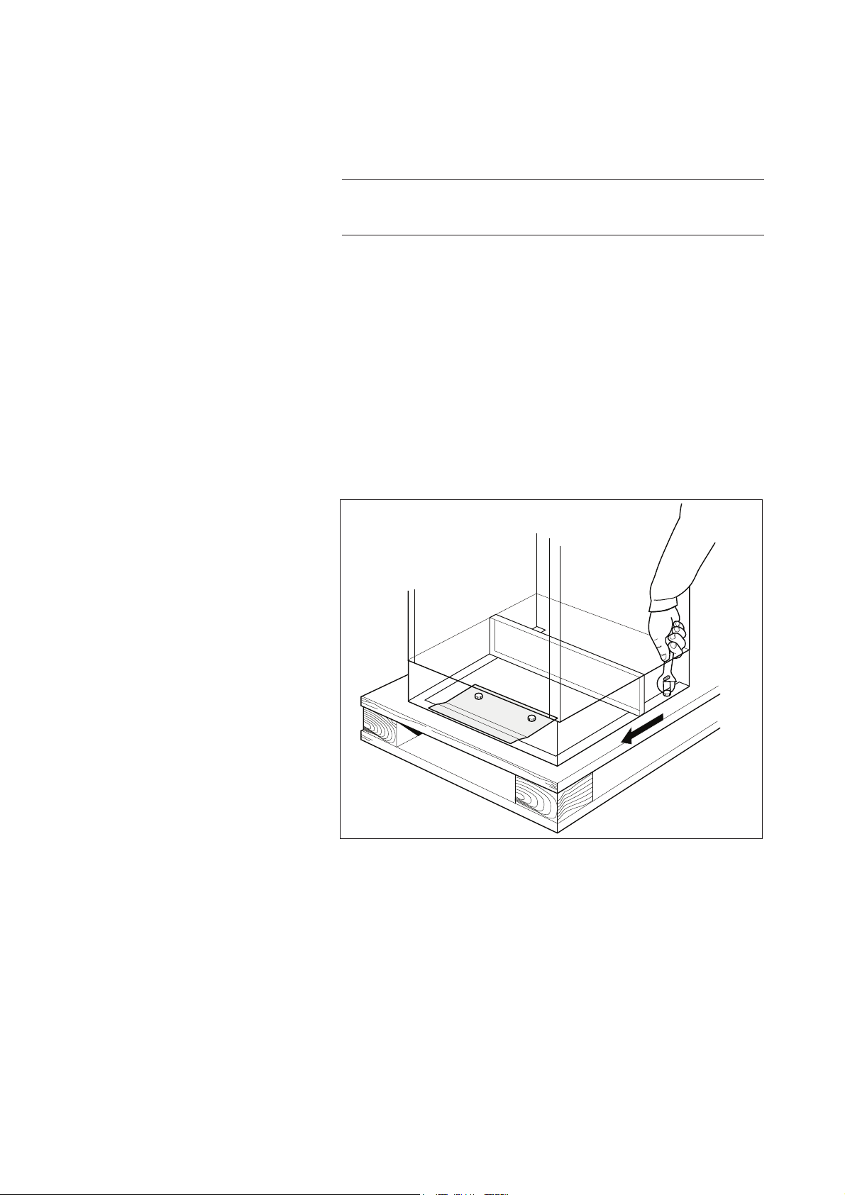
2.2 Unpacking............................................................................................................9
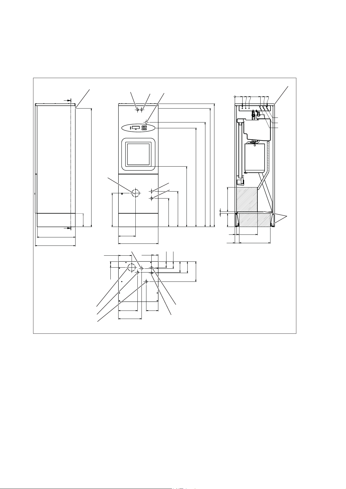
2.3 Diagram showing dimensions and hole pattern.................................................10
2.4 Positioning .........................................................................................................11
2.5 Connecting water...............................................................................................14
2.6 Connecting electric power .................................................................................14
2.6.1 Coupling alternative ............................................................................15
2.7 When the work is complete, check that .............................................................16
2.8 Function check...................................................................................................17
3 TECHNICAL DATA.......................................................................................................19
3.1 Dimensions and weights....................................................................................19
3.2 Connections.......................................................................................................20
3.3 Miscellaneous....................................................................................................21
3.4 Environmental requirements..............................................................................21
3.5 Protection class .................................................................................................21
3.6 Accessories........................................................................................................22
4 WATER QUALITY........................................................................................................23
5 END OF LIFE DISPOSAL............................................................................................25

4
PREFACE
The user manual describes the design and operation of the
machine and the maintenance for which the user is responsible.
The installation manual describes the machine’s installation.
The technical manual describes necessary information for operators
and maintenance personnel. The information in the manual must be
complied with to ensure safe and error-free operation.
Read the manual before use.
Users must read through the manual before using the machine
IRUWKH¿UVWWLPHDVZHOODVIDPLOLDUL]LQJWKHPVHOYHVZLWKWKH
operation of the machine and its safety instructions. Operators and
maintenance personnel must have completed training through the
PDUNHWLQJRUJDQL]DWLRQRI$UMR
The information in this manual describes the machine as
dispatched from Arjo. There may be differences due to
FXVWRPL]DWLRQIRUFXVWRPHUVRUFRXQWULHV
The machine is accompanied by the following documentation:
• User manual
• Installation manual
• Quick guide
The following documentation shall be provided by the sales
company to the end-user on request:
• Technical manual
• Spare parts list
The accompanying Quick guide must be hung up and clearly
visible in the installation area.
$UMRUHVHUYHVWKHULJKWWRFKDQJHWKHVSHFL¿FDWLRQDQGGHVLJQ
without prior notice. The information in this manual was up-to-date
on the date that the manual was issued.

5
1 SAFETY PRECAUTIONS
This machine has a number of built-in safety devices.
To avoid injury, it is highly important not to bypass these safety
devices.
,IWKHHTXLSPHQWLVXVHGLQDPDQQHUQRWVSHFL¿HGE\WKH
manufacturer this can impair the safety equipment on the machine.
Operators and maintenance personnel must undergo safety
training for the machine. All personnel who handle chemicals for
washing and disinfection must understand the washing process,
SRVVLEOHKHDOWKKD]DUGVDQGZD\VRIGHWHFWLQJOHDNVRIWR[LF
chemicals.
Operators and maintenance personnel must undergo regular
training in the operation and maintenance of the equipment.
There must be a documented list of personnel who have been
trained to use the machine. Trained personal must be tested to
verify the training program.

6
1.1 Important
• Take care when handling the chemical agents used in the
machine. Read the details on the container or contact the
manufacturer:
if the agent comes into contact with the operator’s eyes
or skin or if the vapors are breathed in, etc.
about storing the detergent and disposing of empty
containers.
• The equipment must only be used by personnel with proper
knowledge and who are trained to use it. Personnel must also
receive regular training on this equipment.
• Read the user manual thoroughly before use
• 1HYHUXVHWKHÀXVKHUGLVLQIHFWRULI\RXDUHQRWVXUHKRZWR
operate it.
• Follow the written instructions.
• Keep the equipment clean.
• The electric power must be switched off before the machine
cabinet is opened. (The machine cabinet contains electrical
components).
• Make sure that there is always detergent in the bottles.
This is important both for the operation of the machine and
for keeping the washing chamber free from discolorations.
• Always use the equipment in accordance with the local
regulations.
• Always connect the equipment via an RCD (residual
current device).
• $OZD\VXVHDJURXQGHGSRZHUVXSSO\IRUWKHÀXVKHUGLVLQIHFWRU
• If the items have not cooled down after cleaning, be sure
to handle them with care
in order to avoid burns.
• Before starting, check the waste outlet at the bottom of
WKHÀXVKLQJFKDPEHUIRUEORFNDJHV7KLVZLOOHQVXUHWKDW
WKHÀXVKHUGLVLQIHFWRUZRUNVSURSHUO\
• Do not place items that are sensitive to heat or moisture
RQWRSRIWKHÀXVKHUGLVLQIHFWRU

7
1.2 Make sure assembly and installation work is carried out by
• E\TXDOL¿HGSHUVRQQHO
• in accordance with current local regulations and rules.
1.3 Isolator switch
The machine must always be equipped with a separate isolator
switch in the feed power supply. The isolator switch must be easily
DFFHVVLEOHRQDZDOOFORVHWRWKHPDFKLQH7KHH[WHUQDOHOHFWULFDO
isolator switch must be marked “I” and “O” to identify the position
of the switch.
1.4 In an emergency
• Switch off the main switch.
• Close shutoff valves in the water supply line.
1.5 Product liability
CE marking indicating conformity with European Community
harmonised legislation.
$Q\PRGL¿FDWLRQRULQFRUUHFWXVHRIWKHHTXLSPHQWZLWKRXWWKH
approval of Arjo negates Arjo’s product liability.
CE marking indicating conformity with European
Community harmonised legislation
)LJXUHVLQGLFDWH1RWL¿HG%RG\VXSHUYLVLRQ
1.6 Attention symbols
Some of the warnings, instructions and advice in this manual
UHTXLUHH[WUDDWWHQWLRQ7KHV\PEROVDQGGHVLJQVXVHGDUH
Risk of injuries or machine damage.

8
2 INSTALLATION
2.1 General
2.1.1 Make sure assembly and installation work is carried out
7RDYRLGWKHULVNRIEDFNLQMXU\WKLVHTXLSPHQW
should be assembled and installed by at least
two people.
• E\TXDOL¿HGSHUVRQQHO
• in accordance with current local regulations and rules.
• for indoor installation only.
• not to be installed in wet locations.
2.1.2 Installation order
Carry out the installation in the following order:
1. Unpacking
2. Positioning
3. Connecting water
4. Connecting electric power
5. Installation inspection

9
2.2 Unpacking
1RWH%HIRUHLQVWDOOLQJPDNHVXUHWKHÀXVKHUGLVLQIHFWRUKDV
not been damaged in transit.
7KHIROORZLQJLWHPVPXVWDFFRPSDQ\WKHÀXVKHUGLVLQIHFWRUZKHQLW
is delivered:
• Two cabinet keys
• One folder containing documentation
7KHÀXVKHUGLVLQIHFWRULVVXSSOLHGVHFXUHO\EROWHGWRDSDOOHW
1. Remove the packaging.
2. 0RYHWKHÀXVKHUGLVLQIHFWRUDVFORVHWRWKHLQVWDOODWLRQ
position as possible, when still secure to the pallet using
mechanical means.
3. 5HPRYHWKHEROWVVHFXULQJWKHÀXVKHUGLVLQIHFWRUWRWKH
pallet.
001512
Figure 1. Unscrew bolts
4. $VVHVVWKHÀXVKHUGLVLQIHFWRUIRUOLIWLQJIURPWKHSDOOHW8VH
DWOHDVWWZRSHUVRQVWROLIWWKHÀXVKHUGLVLQIHFWRUWRWKHÀRRURU
WRDORZOHYHOZKHHOHGWUROOH\WRDLGPRYHPHQWVWRWKH¿QDO
position.

10
2.3 Diagram showing dimensions and hole pattern
A-A
A
A
900
594
600
570
1477
200
1840
520-580
80-320
120-330
80-110
470
190
130
580
100
114
172
250
310
300
200
1500
7
0
112
162
212
382
432
482
10(2X)
12(2X)
14(2X)
1770
350
46465
200
25
25 300
24
1
3
5
7
6
4
3
217
9
001517
9
1750
8
Figure 2. Diagrams showing dimensions and hole pattern
1. CW, G3/4" female (TWO METERS OF
HOSE FROM THIS POINT ARE INCLUDED
WITH THE MACHINE)
2. HW, G3/4" female (TWO METERS OF
HOSE FROM THIS POINT ARE INCLUDED
WITH THE MACHINE)
3. EXTERNAL STEAM, G1/2" female
4. SOFT WATER, G1/2" female
5. WASTE CONNECTION, S-TRAP,
FLOOR, 110/90.
6. WASTE CONNECTION, P-TRAP, WALL,
110/90.
7. ELECTRICAL CONNECTION. (4 M
CABLE FROM THIS POINT IS
INCLUDED WITH THE MACHINE.)
8. AREAS FOR INCOMING MEDIA.
(DEPENDS ON HOW THE DRAINAGE
IS ARRANGED).
9. HOLE FOR ATTACHING TO THE WALL

11
2.4 Positioning
• Fit the trap to the waste outlet. The trap can be connected
towards the rear or downwards. The pipe diameter is 90 or
110 mm.
• Position the machine and level it using a spirit level held
vertically against the side of the machine. Adjust with the
adjustable feet of the machine using at least a 25 cm long
slotted screwdriver.
001513
Figure 3. Adjusting the feet of the machine

12
001514
Figure 4. Handling panels
• Release the panel and lock it in the service position.
• Measure up and drill the holes for securing the machine to
the wall.

13
001515
Figure 5. Measure up the holes on the wall
• )L[WKHPDFKLQHWRWKHZDOO8VHVXLWDEOHVFUHZVDQGZDVKHUV
for the material of the wall.
1RWH:KHQWKHSOLQWKLVUHPRYHGWKHHQWLUHZHLJKWRIWKH
machine is now supported by the bolts in the wall.
• If the plinth is not going to be used, remove it by unscrewing
the four bolts and pull out the plinth.
001516
Figure 6. Unscrew the plinth

14
2.5 Connecting water
• The connections must satisfy the requirements for water
connection in accordance with the table below.
&ROGZDWHU%OXH Warm water Red
Connection 15 mm (1/2") 15 mm (1/2")
Pressure 100-800 kPa 100-800 kPa
Flow rate 20 l/min at 400 kPa
pressure
20 l/min at 400 kPa
pressure
Temperature & &
• Connect the water supplies.
• 7KHSLSHVPXVWEH¿WWHGZLWKDQDSSURYHG´VKXWRIIYDOYH
• Seal all connections with PTFE tape.
2.6 Connecting electric power
Carry out the electrical installation as follows:
• Install the machine in accordance with installation category
CAT II.
• Make a hole for electric cables in the plinth or baseplate of
the machine.
• Fit the supplied cable bushing and pull the cables through.
001518
Figure 7. Cable gland
• Connect the machine to a separate isolator switch approved
to local standards, which must be mounted on the wall close
to the machine.
• Connect to the protective grounding and to the supply voltage
stated on the type plate. Check that the connection has
suitable overcurrent protection. The correct fuse rating is
stated on the type plate.
• $OOFDEOHVPXVWEHFODVVL¿HGIRUDWOHDVW&
• Fuses as per. Curve C.

15
2.6.1 &RXSOLQJDOWHUQDWLYH
L1
N
PE
L1
N
PE
003026
-X50
L1
L2
L3
N
PE
L1
L2
L3
N
PE
-X50
3N+PE 1N+PE
Figure 8. Electrical connection
L1
L2
PE
L1
L2
PE
003033
-X50
L1
L2
L3
PE PE
L1
L2
L3
-X50
3+PE 2+PE
Figure 9. Electrical connection
Voltage Connection )UHTXHQF\ Fuse 3RZHUUHTXLUHPHQW
400 V 3N+PE (TN) +] 3 × 15 A 5.71 kW
400 V 3N+PE (TN) +] 3 × 10 A 5.51 kW
240 V 3+PE (TN) +] 3 × 15 A 5.71 kW
240 V 2+PE (TN) +] 1 × 20 A 4.35 kW
240 V 2+PE (TN) +] 1 × 10 A 1.36 kW
230 V 3+PE (TN) +] 3 × 16 A 5.51 kW
230 V 1N+PE (TN) +] 1 × 20 A 4.35 kW
230 V 1N+PE (TN) +] 1 × 10 A 1.16 kW
208 V 3+PE (TN) +] 3 × 20 A 5.71 kW
208 V 2+PE (TN) +] 1 × 22 A 4.35 kW
208 V 2+PE (TN) +] 1 × 10 A 1.36 kW
200 V 3+PE (TN) +] 3 × 20 A 5.71 kW
200 V 3+PE (TN) +] 3 × 20 A 5.51 kW
200 V 2+PE (TN) +] 1 × 25 A 4.35 kW
200 V 2+PE (TN) +] 1 × 10 A 1.36 kW
200 V 2+PE (TN) +] 1 × 10 A 1.16 kW
2SHUDWHVZLWKLQ0$,16VXSSO\YROWDJHÀXFWXDWLRQVXSWRRI
the nominal voltage.

16
2.7 :KHQWKHZRUNLVFRPSOHWHFKHFNWKDW
• all parts have been installed according to the installation
manual.
• all screws have been properly tightened.
• there are no sharp edges on any parts that may come into
contact with people.
• all hoses, pipes and connections are intact and free from
defects.
• all the functions of the machine are working properly. Adjust if
necessary.
&DUU\RXWDQ,QVWDOODWLRQ4XDOL¿FDWLRQDQ2SHUDWLQJ4XDOL¿FDWLRQ
DQGD3HUIRUPDQFH4XDOL¿FDWLRQDFFRUGLQJWR,62EHIRUH
putting the machine into service.
Incorrect use may result in damage to objects and personal injury.

17
2.8 Function check
Note! Make sure that the suction hose in the dosing pump
is full of agent before beginning. The dosing pumps can be
RSHUDWHGVHSDUDWHO\LQWKHVHUYLFHSURJUDPWR¿OOWKHKRVHV
ZLWKDJHQWOLQHVH7HFKQLFDOPDQXDO
• &KHFNWKDWWKHÀXVKHUGLVLQIHFWRULVFRQQHFWHGWRWKHFRUUHFW
supply voltage and that it is protected by a fuse of the correct
rating as shown on the type plate.
• Turn on the isolator switch. Check that all lamps on the panel
OLJKWXSDQGWKDWWKHEX]]HUVRXQGV7KHGLVSOD\WKHQVKRZV
the current program version, followed by the preselected
program. Open the water valves.
• If the machine has detergent dosing: Press and check
that the light in the button comes on.
• Check that the temperature of the incoming water is correct.
7KHWHPSHUDWXUHPXVWEHLQWKH&UDQJHIRUKRWZDWHU
DQGQRWOHVVWKDQ&IRUFROGZDWHU
Note! Make sure that the suction hose in the dosing pump
is full of agent before beginning. The dosing pumps can be
RSHUDWHGVHSDUDWHO\LQWKHVHUYLFHSURJUDPWR¿OOWKHKRVHV
ZLWKDJHQWOLQHVH7HFKQLFDOPDQXDO

18
• Start a program with the machine empty and check that:
yellow light flashes for 6 seconds.
yellow light on comes on.
- the temperature rises continuously until the cooling
phase begins.
SDXVHIRUKHDWLQJXSGRHVQRWH[FHHGDERXWPLQ
WKHWHPSHUDWXUHUHDFKHV&
the green lamp at lights up and the display shows U7
(hot goods).
ZKHQWKHGRRULVIXOO\RSHQFKHFNPD[WHPSHUDWXUH
Typhoon
2 4
5
6
3
1
Figure 10. Control panel
1. Yellow: Process running
2. Green: Process complete
3. Red: Disinfection not achieved or other error code F
4. Display
5. Open/close door.
6. Sensor to open/close door and to start preselected
program
• The machine has a dosing system for descaler and possibly
for processing agent (optional). Start a standard program
and check that the disinfector consumes the correct amount.
For descaler, the amount per program is usually about 1.5 -
4.0 ml (follow the supplier’s recommendations). Check the
service program in the Technical Manual for checking and
adjusting the dosage amount.
Check that the door can be opened and closed with the
sensor.
Check that there are no water leaks. If necessary,
tighten connections and pipe couplings.

19
3 TECHNICAL DATA
3.1 Dimensions and weights
Dimensions and weights
Weight 135 kg
Width 600 mm
Depth 600 mm
Height (incl. plinth 200 mm) 1840 mm

20
3.2 Connections
Water consumption
Standard program l/process
Cold Water
Connection 15 (1/2") mm
Pressure 100-800 kPa
Flow rate 20 l/min
Hot Water
Temperature &)
Connection 15 (1/2") mm
Pressure 100-800 kPa
Flow rate 20 l/min
Softened water
Temperature &)
Connection 15 (3/4") mm
Pressure 100-800 kPa
Flow rate 20 l/min
Steam
Connection 15 (1/2") mm
Pressure 30-300 kPa
Flow rate 0.3 kg/process
Drainage
Connection Ø 90/110 mm
Other manuals for Typhoon
3
Table of contents
Other Arjo Laboratory Equipment manuals
Popular Laboratory Equipment manuals by other brands

Dolan-Jenner
Dolan-Jenner Fiber-Lite MI-150 Operation manual

Thermo Scientific
Thermo Scientific 89852 user guide

Opentrons
Opentrons GEN1 manual

Sanuvox
Sanuvox ASEPT.2X quick start guide

Nippon
Nippon FastGene FG-02 instruction manual

TORREY PINES SCIENTIFIC
TORREY PINES SCIENTIFIC EchoTherm IC25 operating manual

Buchi
Buchi Lyovapor L-300 Operation manual

Thermo Scientific
Thermo Scientific 1500 A2 Series operating manual

NSK
NSK PRESTO AQUA LUX Operation manual

NT-MDT
NT-MDT Solver Next instruction manual

ViscoTec
ViscoTec PreeFlow eco-CONTROL EC200 DUO Operating and maintenance instructions

BEHR
BEHR behrotest R 104 T user manual