Armstrong 21AR Instruction Manual

IB-22
Installation and Maintenance
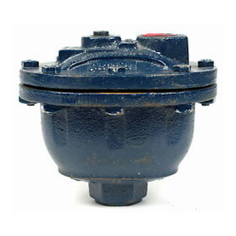
ARMSTRONG NO. 21AR AND NO. 21-312AR AIR VENTS
This bulletin should be used by experienced personnel as a guide
to the installation of Armstrong No. 21-AR and No. 21-312AR air
vents and their repair parts.
Selection or installation of
equipment should always be accompanied by competent technical
assistance.
We encourage you to contact Armstrong or its local
representative if further information is required.
The maximum operating pressures for No. 21AR and No. 21-312 AR
are listed in Table 1.
DO NOT EXCEED THE MAXIMUM OPERATING
PRESSURE.
The vessel design limitations of the No. 21-AR are 250 psig
@
450'F.
Vessel design limitations for the No. 21-312AR are 750 psig
@
lOOoF.
and 500 psig
@
750'F.
Table 1
I
No. 21 AR
I
l/16
With 4% oz. Float
I
250 psi
(Sp.
Gr. 1.00 to
.85)
I
1.
2.
Model Number
No. 21-312 AR,
Forged Steel
With Std.
5 oz. Float
No. 21-312V AR,
Forged Steel
With Std.
5 oz. Float
and High Leverage
Mechanism
Ori;ic.zp”
l/32
;;it
9/64
l/8
3/32
5/64
l/16
Specific Gravity,
Range, 1.00 to 35
25 psi
35 psi
55 psi
65 psi
165
PSI
300
psi
430
psi
680 psi
FOR TYPICAL INSTALLATIONS, SEE FIG. l-7.
The inlet and the outlet piping should be the same size as
the air vent connections. Do not reduce the size of the
inlet on light loads; however, smaller pipe or tubing may be
used on the outlet. Keep the piping as short as possible,
with a minimum of fittings andvalves.
DO NOT USE ELBOWS IN
THE INLET
LINE,FROM
THE EQUIPMENT TO THE VENT.
Install gate valves so the air vent can be isolated from the
system to permit cleaning and repair. DO NOT USE GLOBE
VALVES.

b
&
8
ARMSTRONG 21AR AND 21-312AR AIR VENTS
3.
4.
5.
6.
7.
8.
9.
10.
11.
1.
2.
Before installing the vent, flush out the line to remove
loose dirt.
Use pipe dope or teflon sparingly and on male
threads only. Leave the end thread exposed to avoid
introducing sealant into the system.
DO NOT use a pipe strainer in the line leading to the vent.
For occasional venting, a single pipe
3/4"
or larger is a
suitable connection.
Once the system is filled with water,
only small additional amounts of air need to be vented, so
there is no difficulty in getting air to enter the vent
countercurrent to the water displaced.
For continuous operation,
an equalizing line is usually
necessary. Where gas enters the system continuously or when
very fast venting is required,
an equalizing line should be
provided, as shown in Fig. 3.
Be certain the vent is installed properly, with the CAP AT
THE TOP for air and gas relief service.
Install the air vent at the high points of the system.
See
the accompanying diagrams for typical installations.
Air vents should be installed so that they can be checked
periodically.
A drain line should be piped to a floor
drain,
slop sink, or other visible location where
maintenance personnel can regularly check for leakage.
The pipe plug in the cap of the air vent can be replaced
with a test cock or test valve for vent testing or even
manual venting. A test cock makes it possible to check that
the vent is not air bound due to the orifice being clogged.
In addition, the manual test cock will enable the operator
to vent the unit manually should the automatic vent fail.
If the vent is installed in an inaccessible location, a
l/4"
copper tube drain line to a slop sink, floor drain, or other
visible location makes periodic inspection practicable.
No discharge from the vent is normal on hydronic systems,
but is not proof that the vent functions properly. To check
the air vent,
crack the test cock. If the vent is working
correctly, a little air should escape, followed by water.
Vent Does Not Open.
If a lot of air escapes out of the test cock before water
begins to discharge, it is a sign that the vent body was
full of air and that the float did not sink to open the
valve,
or that the valve was plugged. Isolate the vent by
closing the gate valve before opening for inspection.
a.
Remove the vent cover and inspect the mechanism. If
the mechanism cannot be made to operate freely after
cleaning and inspection, order a new assembly.
b.
Check the orifice for dirt. Clean the orifice. If the
orifice cannot be cleared, order a new mechanism.
c.
On new installations, an air vent may fail to open if
the orifice is too large for the operating pressure.
Replace the mechanism with one sized for
your
operating
pressure.
2

ARMSTRONG 21AR AND 21-312AR AIR VENTS
d.
An unusual increase in system pressure may cause the
air vent to lock shut. Either eliminate the cause of
the increased pressure or replace the mechanism with
one that can handle the peak pressures.
3.
Vent Fails to Close Tightly (Leaks Water).
a.
Dirt may be lodged in the orifice.
Clean the orifice,
the mechanism, the body, and the cap.
b.
The valve and seat may be worn.
Replace the whole
mechanism.
c.
There may be a leak in the float. Disconnect the float
and shake it close to your ear. If liquid has leaked
inside you will be able to hear it sloshing. Replace
the float.
d.
An unlikely possibility is that the float has
collapsed. Replace the float.
For help with unusual installations or service problems, contact
your Armstrong Representative or the Armstrong Machine Works
Applications Engineering Department.
1.
2.
3.
4.
5.
DO
PLACEMENT OF LEVERAGE
SYSTEM
FOR NO.
21-AR.NO.
21-3U
Make sure the parts you have received are for the correct
orifice size for your operating pressure.
The orifice size
(7/32”,
for example) is stamped on the valve seat.
Remove the air vent cap and place it in a vise with the
mechanism up.
Disassemble the float and lever mechanism by removing the
valve lever pin and the valve seat.
Clean all dirt, pipe scale, and foreign materials from the
cap, especially from the threaded holes.
Place the valve seat through the hole in the valve lever
clip and tighten both parts into the air vent cap. When the
valve seat is tightened, the lever clip should be
symmetrical with respect to the gasket surfaces to the left
and right of it and with respect to the centerline of the
cap.
The ears for the valve lever pin should be on the side
of the valve seat closest to the gasket surface (away from
the center of the cap).
NOT use pipe dope or lubricant on the valve seat threads. The
-
.
seal is made,
not by the threads, but by metal to metal contact
at
the ground end of the valve seat. Make sure the seating area
in the cap is clean before screwing the valve seat into position.
6.
Use the valve lever pin to assemble the valve lever to the
valve lever clip.
The ears of the valve lever fit in
between the ears of the valve lever clip.
3

ARMSTRONG 21AR AND 21-312AR AIR VENTS
7.
8.
9.
10.
11.
12.
13.
14.
15.
16.
17.
18.
Check the sideways motion of the valve lever in the lever
clip.
Total motion should be about
l/32"
(l/64"
to the left
and to the right of center). Adjustments can be made by
tapping the ears of the valve lever clip VERY LIGHTLY left
or right with a SMALL HAMMER (4 oz.).
Check the seating of the valve. The point of the cone valve
should easily drop into the orifice with no hang-up on the
edges of the orifice. When the valve is shut, the valve
lever should be visually parallel to the valve lever clip.
(SeeFigure 8) Adjustments maybe made to the front or back
of the lever pin ears by tapping VERY LIGHTLY with a SMALL
HAMMER.
Use the float screw to assemble the float to the valve
lever.
Remove the cap from the vise, invert it, and assemble it to
the air vent body.
Remove the plug in the cap of the air vent.
Turn the air vent over so that the cap is at the bottom.
Insert a pencil or rod into the plug hole to lift the float.
The float should readily move upward and strike the body
wall. All motion must be free and easy. Lowering the float
should result in the valve seating in the orifice and no
contact between the float and the body of the air vent.
When moving the float,
up and down.
the pencil or rod should travel
l/4"
When the valve is in position to function properly,
disassemble the cap from the body. Remove the float. Tap
the valve VERY
L.IGHTLY
with a SMALL HAMMER (4 oz.) to
produce a seating ring.
Replace the float.
Put the body gasket in place.
Assemble the cap to the body.
Check the float motion as in step 13 above. If the valve
seats properly, replace the plug.
IB-22
9/85
4

A
4
lb
ARMSTRONG 21AR AND 21-312AR AIR VENTS
TO DRAIN
:
c
TEST PET COCK
ARMSTRONG NO.21
RETURN
HIGH POINT ON
WATER MAIN
Fig. 1. Air vent on high point of
main of hydronic heating system.
Test pet cock is optional. Gate valve
for isolating vent to permit cleaning
and repair if necessary.
TEST
PET C ARMSTRONG NO.21
AIR VENT
TUBING TO
FLOOR DRAIN
OR SLOP SINK
WATER PIPING
Fig. 4-Installation of automatic a’r vent on
rote,
piping.
TEST PET COCK
ARMSTRONG NO.21
AIR VENT
HOT WATER
UNIT HEATER
Fig. 7
-
Installation of automatic air vent on
hot water unit heater.
Fig. 2. Vent to remove air when fill- Fig..3 Hook up for No. 21AR to
ing tank with liquid. If moderate
vent surplus air from a water storage
amounts of air must be vented after
tank. If vent is to be isolated use gate
tank is filled use
3/4”
pipe and avalves. Pipe size can be l/2”. Line
314”
gate valve (if trap is to be
A-A shows water level
-
position vent
isolated for cleaning and/or repair).
to secure level desired.
NO.
21
Fig. 5-1nstollation of automatic air vent on
loop in piping.
I
TO DRAIN
--TEST PET COCK
‘ARMSTRONG NO.
21
AIR VENT
:
I
VENTING BNEL
COIL
Fig.
6
-Installation of automatic air vent on
panel coil.
VALVE
LEVEE
VALVE
LEVEP
CL\P
Fig.
8.
L
SEAT
This manual suits for next models
1
Other Armstrong Fan manuals