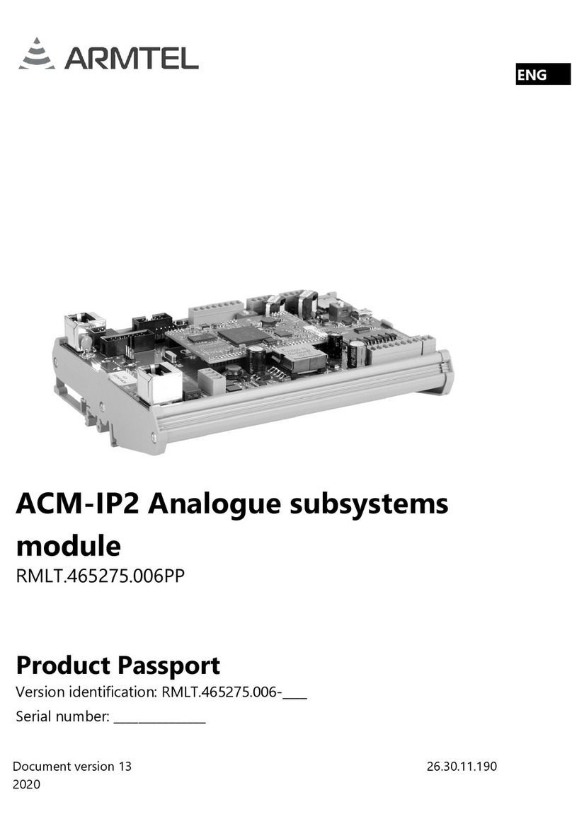
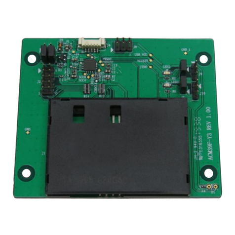
ARMTEL ACM-IP2 User manual

ACM-IP2 Analogue subsystems
module
RMLT.465275.006UM
User Manual
Document version 12
26.30.11.190
2020
ENG

armtel.com
© Armtel info@armtel.com

ACM-IP2 ANALOGUE SUBSYSTEMS MODULE
User Manual
armtel.com page 1/28
info@armtel.com © Armtel
ENG
INTRODUCTION
This User Manual is intended for introducing ACM-IP2 Analogue subsystems module
RMLT.465275.006 manufactured by Armtel LLC, Russia to the User.
ACM-IP2 Analogue subsystems module provides the functions of bi-directional
conversion of the digital IP-interface to analog for providing Public Address/ General Alarm
communication systems with subscriber intercoms equipped with an analog interface, and
also provides the ability to listen to recorded or broadcasted audio messages to subscriber
devices by the built-in amplifier.
Short name of product – ACM-IP2.
Maintenance personnel for ACM-IP2 shall be appointed by the management at
the installation site.
The maintenance personnel shall be required to know the operating procedure of
ACM-IP2 to the extent provided for by the User Manual.
Duties of the maintenance personnel shall include maintenance of ACM-IP2 in
accordance with this User Manual.
ATTENTION! In connection with systematic work to improve the design and
manufacturing technology, it is possible some discrepancy between the description and the
supplied product, which does not affect its operation or maintenance.

ACM-IP2 ANALOGUE SUBSYSTEMS MODULE
User Manual
page 2/28 armtel.com
ENG
SAFETY PROVISIONS
During installation and operation of ACM-IP2, observe safety precautions laid out in
local regulations on electrical safety.
In order to ensure fire safety, follow the following rules:
−before connecting the product to the power supply, make sure the power and
communication cables are properly insulated;
−protect power and communication cables from damage.
To avoid electric shock, do not:
−operate the product with a damaged power or communication cable.
ATTENTION! NEVER DISMANTLE THE PRODUCT CONNECTED TO MAINS OR
EXTERNAL POWER SUPPLY.
Do not use the product in rooms with high humidity (more than 80 %) or conductive
dust.
The safety provisions for specific operations described in this manual are marked with:

ACM-IP2 ANALOGUE SUBSYSTEMS MODULE
User Manual
armtel.com page 3/28
info@armtel.com © Armtel
ENG
CONTENTS
INTRODUCTION.................................................................................................................................................................... 1
SAFETY PROVISIONS........................................................................................................................................................... 2
CONTENTS .............................................................................................................................................................................. 3
1 DESCRIPTION AND OPERATION................................................................................................................................. 4
1.1 Features....................................................................................................................................................................... 4
1.2 Main specifications ................................................................................................................................................. 6
1.3 Scope of supply........................................................................................................................................................ 8
1.4 Design.......................................................................................................................................................................... 9
1.5 ADSL-IP2 Adapter .................................................................................................................................................11
1.6 Labeling.....................................................................................................................................................................13
1.7 Package.....................................................................................................................................................................13
2 INTENDED USE ................................................................................................................................................................14
2.1 Operating limits .....................................................................................................................................................14
2.2 Preparation for use ...............................................................................................................................................15
2.3 Installation, connection and dismantling .....................................................................................................15
2.4 Operation .................................................................................................................................................................17
3 MAINTENANCE................................................................................................................................................................19
3.1 General guidelines ................................................................................................................................................19
3.2 Safety precautions.................................................................................................................................................19
3.3 Maintenance procedure......................................................................................................................................19
3.4 Checking operability ............................................................................................................................................19
4 REPAIR ..............................................................................................................................................................................20
5 STORAGE............................................................................................................................................................................20
6 TRANSPORTATION.........................................................................................................................................................21
7 DISPOSAL...........................................................................................................................................................................21
APPENDIX A (reference) ACM-IP2 Connection diagrams ...................................................................................22
APPENDIX B (reference) ACM-IP2 External appearance......................................................................................26

ACM-IP2 ANALOGUE SUBSYSTEMS MODULE
User Manual
page 4/28 armtel.com
ENG
1 DESCRIPTION AND OPERATION
1.1 Features
ACM-IP2 is designed for use in distributed and centralized digital Intercom and Public
Address / General Alarm communication systems (based on allotted SIP server) at industrial
and transportation facilities.
АСМ-IP2 enables to use analogue equipment and to interact with automation and
alarm units.
АСМ-IP2 is installed in communication cabinets, racks located in offices and control
rooms.
ACM-IP2 has two versions. Versions of АСМ-IP2 are shown in Table 1. External
appearance is given in Appendix B.
Table 1 - Versions of АСМ-IP2
Identification ADSL-IP2 Adapter
RMLT.465275.006
Not included
RMLT.465275.006-01
Included
ACM-IP2 can provide the following functions:
−simplex communication with analogue and digital terminal units via «Armtel-IP»
and SIP protocols;
−communication with analogue and digital terminal units using ADSL channel
and wireless data transfer Wi-Fi channel (for version RMLT.465275.006-01);
−construction of loud-speaking zonal alarm system (up to eight zones) with
the help of additional power amplifier and additional modules with relays
ARMT.665200.117 for switching of loudspeaker lines;
−recording of voice messages from terminal units to SD-card in WAV file format
with linear encoding of 16 bit 16 kHz, the size of the message depends on the
available space on the memory card of the unit. The total duration of messages
is more than 1500 minutes;
−playback of recorded voice messages on the terminal units;
−providing of calls priorities, set during configuration of the subscriber units, via
SIP and «Armtel-IP» protocols.

ACM-IP2 ANALOGUE SUBSYSTEMS MODULE
User Manual
armtel.com page 5/28
info@armtel.com © Armtel
ENG
Configuration of АСМ-IP2 is performed from the administrator's PC, on which
the "IPN2 Configuration Software" RU.RMLT.00041-01 should be installed.
Figure 1 shows several alternatives of АСМ-IP2 usage.
Figure 1 – Example of АСМ-IP2 operation within distributed intercom and alarm systems
For example, organization of simplex communication sessions on routes:
- DIS-IP2 – Ethernet interface – Fast Ethernet Switch – Ethernet interface – АСМ-IP2 –
AW call station;
- AW call station – АСМ-IP2 – USB interface – ADSL-IP2 – WI-Fi access point – Ethernet
interface – Fast Ethernet Switch – Ethernet interface – DIS-IP2;
- AW call station – АСМ-IP2 – USB interface – ADSL-IP2 – ADSL interface – DSLAM –
Ethernet interface – Fast Ethernet Switch – Ethernet interface – DW-IP2.
Organization of loud-speaking Public address / General alarm sessions on routes:
- DIS-IP2 – Ethernet interface – Fast Ethernet Switch – Ethernet interface – АСМ-IP2 –
external amplifier – 4x Relay modules – loudspeakers (up to 8 pcs.);
- AW call station – АСМ-IP2 – Ethernet interface – Fast Ethernet Switch – Ethernet
interface – модуль АСМ-IP2 – built-in amplifier – loudspeaker (up to 1W).

ACM-IP2 ANALOGUE SUBSYSTEMS MODULE
User Manual
page 6/28 armtel.com
ENG
1.2 Main specifications
Main specifications and operational characteristics of ACM-IP2 are given in
the Table 2.
Table 2 – Main specifications and operational characteristics
Parameter Value
Main specifications of ACM-IP2
Power supply by PoE plus line (IEEE 802.3at), V
-48
Rated voltage, V
-48
External power supply voltage range, V
from -36 to -60
Maximum current consumption at nominal power supply voltage:
- for version RMLT.465275.006, mA
- for version RMLT.465275.006-01, mA
510
610
Bandwidth (-3 dB level), Hz
from 300 to 6800
Communication interface
100BaseT Ethernet*
Communication protocol
«Armtel-IP», SIP
Overall dimensions, mm
174×125×55
Weight, kg
(0,3 ± 0,02)
Parameters of analogue lines
Number of analogue lines, pcs.
2**
Rated input signal, mV (dB)
775 (0)
Rated output signal, mV (dB)
Signal/noise ratio, min, dB
75
Internal resistance of the line, max, kOhm
1,0
* Two Ethernet ports, one being stand-by, also with power supply via PoE line.
** One line is in operation, the second line is reserved.

ACM-IP2 ANALOGUE SUBSYSTEMS MODULE
User Manual
armtel.com page 7/28
info@armtel.com © Armtel
ENG
Table 2 – Main specifications and operational characteristics (end)
Parameter Value
Parameters of built-in amplifier
Number of channels of the built-in amplifier, pcs.
2***
Power of integrated amplifier per one channel
(at 8 Ohm load), min, W
1,0
Parameters of control lines
Number of control lines (programmable), pcs.
8
Input current, max, mA
5,0
Output current, at least, mA
35
Main specifications of ADSL-IP2 (for version RMLT.465275.006-01)
Power supply, V
3,3; 5,0
Communication interface
ADSL, ADSL2, ADSL2+
Communication protocol by ADSL line
IEEE802.3, IEEE802.3u,
ITU G.992.1…992.5
Communication interface
WI-FI 2.4
Communication protocol for Wi-Fi
IEEE 802.11a/b/g/n
Communication interface with ACM-IP2
USB 2.0
Overall dimensions with an antenna raised upright, mm
183×85×78
Weight, kg
(0,18 ± 0,01)
Operational characteristics
Electrical protection class (under GOST IEC 61140-2012)
III
Climatic category according GOST 15150-69
NF4.1
1)
Relative air humidity at 25 °С, %
up to 80
Temperature range,
°
С
from - 5 to + 55
*** Transmission of audio information is carried out simultaneously through 2 channels.
1) Indoor use. АСМ-IP2 is installed in communication cabinets, racks located in offices and
control rooms

ACM-IP2 ANALOGUE SUBSYSTEMS MODULE
User Manual
page 8/28 armtel.com
ENG
1.3 Scope of supply
The scope of supply for ACM-IP2 is provided in Table 3.
Table 3 – Scope of supply
Identification Name
Quanti-
ty, pcs. Note
RMLT.465275.006* ACM-IP2 Analogue subsystems module 1
Product components
RMLT.468158.001
ADSL-IP2 Adapter
1
For version
RMLT.465275.006-01
Wi-Fi antenna NETIS PA105S 2,4 GHz
1
ARMT.665230.207.002
Flexible cable
1
Operational documentation
RMLT.465275.006PP
Product Passport
1
RMLT.465275.006UM
User Manual
1
* Version according to the contract for the supply. Parameter of versions see Table 1.

ACM-IP2 ANALOGUE SUBSYSTEMS MODULE
User Manual
armtel.com page 9/28
info@armtel.com © Armtel
ENG
1.4 Design
ACM-IP2 is a printed board with electronic components, inserted in casing and fixed
on DIN-rail 35 mm wide.
ACM-IP2 external appearance and overall dimensions are given at Figure 2.
a) elements view
b) bottom view
Figure 2 – ACM-IP2 external appearance and overall dimensions
Figure 2 shows:
−А2 – CPU-IP module;

ACM-IP2 ANALOGUE SUBSYSTEMS MODULE
User Manual
page 10/28 armtel.com
ENG
−Х1, X2 – sockets for connection to Ethernet (including power supply by PoE plus);
LED indicators on sockets X1 and X2:
1. Green – ON when there is physical connection with Ethernet network, blinking
when network interface is active (receiving or transmitting of data packages);
2. Orange – ON when the unit is powered from the PoE source;
−Х3, Х4 – sockets to connect analogue lines;
−Х8 – output socket of the integrated audio amplifier, (can be used, for example,
to listen to audio messages transmitted to terminal units);
−Х11 – socket of discrete lines (control lines), software configurable or as input
for connection, for example, direct call key of the terminal units or as output (for
load connection);
−Х19 – socket for external module ADSL-IP2 Adapter RMLT.468158.001;
−Х21 – socket to connect external power supply source, external power is
supplied to contacts 2 «-48V» and 3 «+0V». when the module is supplied by
РоЕ plus line, voltage is output to the same contacts 2 «-48V» and 3 «+0V»;
−Х22 – negative potential on the load line, for example, the relay windings;
−Х42 – micro-SD card slot with card installed.
Each ACM-IP2 contains firmware and factory settings (IP address and MAC address).
To provide communication, IP network built using standard network equipment is needed.

ACM-IP2 ANALOGUE SUBSYSTEMS MODULE
User Manual
armtel.com page 11/28
info@armtel.com © Armtel
ENG
1.5 ADSL-IP2 Adapter
ACM-IP2 variant RMLT.465275.006-01 includes ADSL-IP2 Adapter, which provides
communication with end devices by ADSL line or over a wireless data link Wi-Fi. ADSL-IP2
Adapter external appearance and overall dimensions are given at Figure 3.
a) elements view b) side view
1 – Adapter board; 2 – Modem ADSL Module IB02 v5.0; 3 – Wi-Fi antenna NETIS PA105S;
4 –RJ-45 socket (not used); 5 – socket RJ-12 6P6C connection ADSL line;
6 – socket connect ACM-IP2 by USB.
Figure 3 – ADSL-IP2 Adapter
The ADSL-IP2 Adapter is mounted on DIN-rail similarly as ACM-IP2 and is connected
to it by the flexible cable supplied with the one. The operating mode for ADSL-IP2 Adapter
(ADSL or Wi-Fi) is set by software during configuration of ACM-IP2. Communication with the
ADSL-IP2 Adapter is executed by IP-address, while the input signal via USB-interface is
transmitted to ACM-IP2, thus providing communication with the terminal analog units.
When working on ADSL line, ADSL-IP2 Adapter supports standards IEEE802.3,
IEEE802.3u, ITU G.992.1 ... 992.5, which provide duplex communication with non-symmetrical
channel bandwidth and the frequency range from 26 kHz to 1.1 MHz with the speed of
the incoming stream is up to 24 Mbit / s, which makes it possible to use a twisted pair cable
to organize the system. The length of the communication line using ADSL can reach 5.5 km,
if the conditions specified in the ITU G.992.1 ... 992.5 standards are met.

ACM-IP2 ANALOGUE SUBSYSTEMS MODULE
User Manual
page 12/28 armtel.com
ENG
When working on a wireless data link, Wi-Fi adapter supports IEEE 802.11a/b/g/n
protocol to operate at 2.4 GHz with a bandwidth of up to 20 MHz. The speed of data transfer
using Wi-Fi technology reaches 300 Mbit / s. The adapter uses all-directional Wi-Fi antenna
with a gain of 5dBi, which enables to place the access point at a distance of up to 100 meters
from the adapter or more - depending on the characteristics of the antenna on the access
point.

ACM-IP2 ANALOGUE SUBSYSTEMS MODULE
User Manual
armtel.com page 13/28
info@armtel.com © Armtel
ENG
1.6 Labeling
On the side fasteners ACM-IP2 and ADSL-IP2 is placed bilingual nameplate.
The nameplate contains the following information:
−name, trademark and reference information of the manufacturer;
−product name and description;
−temperature range;
−commercialization mark for products on the market of Customs Union member states;
−special waste disposal mark;
−product serial number;
−date of manufacture;
−other information if necessary.
The serial number is unique for each product.
1.7 Package
ACM-IP2 with the assembly kit and documents, which come with the supply package,
is packed in consumer package (cardboard box).
A label in Russian language and English language is glued onto the consumer package,
said label containing the following inscriptions and symbols:
−product name and description;
−name, trademark and reference information of the manufacturer;
−handling symbols according to GOST 14192-96 and CU TR 005/2011;
−commercialization mark for products on the market of Customs Union member
states;
−serial number and date of manufacture.
The package is made according to the drawings of the product manufacturer and
enables storage of the ACM-IP2, provided requirements set in Section 5 are met.
For shipment of the ACM-IP2 from the manufacturer, consumer package contents are
placed in the package place, which ensures protection from mechanical damage, direct
ingress of atmospheric precipitation, dust and solar radiation during transportation.

ACM-IP2 ANALOGUE SUBSYSTEMS MODULE
User Manual
page 14/28 armtel.com
ENG
2 INTENDED USE
The product is designed for continuous 24-hour a day operations. After
commissioning, the product does not require operator intervention, unless:
−maintenance;
−product configuration changes.
Maintenance personnel must be strictly guided by this document in compliance with
safety regulations.
The product along with the operational documentation is delivered to the customer in
packaged form.
2.1 Operating limits
2.1.1 ACM-IP2 shall be used under exposure factors and ambient parameters
which do not exceed permissible values given in Table 2. When using the product,
safety precautions laid out in “Occupational safety rules when operating electrical
installations” should be complied with when working with electrical receivers with
voltage of up to 1000 V.
2.1.2 In case of lack of power supply PoE plus, in addition to connecting
the communication cable, it is necessary to supply an external 48 V supply from a DC power
source with a power of at least 30 W to contacts 2, 3 of the socket X21 of the ACM-IP2. The
connection should be carried out with a 2-core cable with a cross section of at least 0.35mm2.
2.1.3 When installing ACM-IP2 (version RMLT.465275.006-01) together with the
ADSL-IP2 Adapter in fully enclosed metal telecommunication cabinets, stable operation of
the product via wireless Wi-Fi communication is not guaranteed.
2.1.4 A restart may delay the initialization of the ACM-IP2. This feature is characteristic
in case of power supply by PoE plus line, as well as using the ADSL communication line (in
case of restarting the IP DSLAM).
2.1.5 The requirements for operating conditions and the choice of the place of
installation given in this document take into account the most typical factors that
affect the operation of ACM-IP2.
Factors that cannot be predicted, estimated or verified, and which the manufacturer
was unable to factor in during development may exist or arise during operation at the
operating facility.
In the event of such factors, find another operating site where said factors do not exist
or do not affect operation of the product.

ACM-IP2 ANALOGUE SUBSYSTEMS MODULE
User Manual
armtel.com page 15/28
info@armtel.com © Armtel
ENG
2.2 Preparation for use
The following operations should be performed in preparation for ACM-IP2 unit
preparation for use:
−removing ACM-IP2 from the shipping container;
−removing ACM-IP2 from the customer package;
−check the scope of supply of ACM-IP2 according to product passport;
−inspect ACM-IP2 enclosure visually, no mechanical damages (cracks, dents, etc.)
on the enclosure, board and elements are allowed;
−install ACM-IP2 at the operation site (click on the DIN-rail). The location in the
cabinet should be chosen taking into account the convenience of access to the
module for connecting the power and communication wires, as well as for
maintenance. In the same way, install ADSL-IP2 Adapter in ACM-IP2 version of
RMLT.465275.006-01 in the cabinet.
2.3 Installation, connection and dismantling
2.3.1 ACM-IP2 version of RMLT.465275.006 is connected via 100BaseT Ethernet
interface. The on-site connection is carried out using multi-wire UTP type cable, crimped
with RJ-45 plugs, which is connected to X1 socket (or to X2 socket) of RJ-45 in accordance
with Figure 2. On the other side, the cable is connected to a network unit with PoE plus
injector function. For version ACM-IP2 RMLT.465275.006-01, it is necessary to connect the
external power to X21 socket and connect ADSL-IP2 Adapter to X19 socket in accordance
with Figure 2 with the cable from the adapter package. If you are using ADSL line, connect
ADSL-IP2 main cable with RJ-12 plug to X25 socket of the ADSL-IP2 module or configure a
Wi-Fi router by contacting the network provider.
100BaseT Ethernet interface in this case is connected to either DSLAM IP router or
Wi-Fi router.
Designation and external appearance of outputs of 100BaseT Ethernet RJ-45 socket for
ACM-IP2 and RJ-12 of ADSL-IP2 Adapter are given in Appendix A.
2.3.2 An analog terminal unit is connected to the X3 (or X4), X11 connectors. Connection
examples are given in Appendix A. Connection to terminal units must be performed with a
multicore (four or eight-wire) cable with a cross section not less than 0.12 mm2. Before connection,
the cable ends should be stripped from insulation for the length of 5 mm, tin-coated and are
connected to the return (cable) parts of the dockets installed on the unit.

ACM-IP2 ANALOGUE SUBSYSTEMS MODULE
User Manual
page 16/28 armtel.com
ENG
2.3.3 Installation of IP-address for ACM-IP2
During production, each ACM-IP2 is assigned the same default IP-address:
192.168.100.10, subnet mask: 255.255.255.0. Since units with the same IP-
addresses are not allowed on the same network, it is necessary to set the network parameters
for each ACM-IP2 before being connected to the network. To this end, you can use direct
connection of ACM-IP2 to the service computer. In this case, to power ACM-IP2, you should
use PoE injector or supply -48 V to "X21" socket from external DC power source.
Make records in the product passport about location and time of АСМ-IP2 installation
and about IP-address installed.
2.3.4 Dismantling:
−disconnect the interface cable from the RJ-45 socket;
−disconnect the external power supply (if used);
−disconnect the control lines with terminal units and the ADSL-IP2 Adapter (for
version RMLT.465275.006-01);
−remove the АСМ-IP2 and the ADSL-IP2 Adapter (for version RMLT.465275.006-01)
from the DIN-rail;
−pack АСМ-IP2 into the customer manufacturer’ package. If necessary, pack
АСМ-IP2 into a shipping container.

ACM-IP2 ANALOGUE SUBSYSTEMS MODULE
User Manual
armtel.com page 17/28
info@armtel.com © Armtel
ENG
2.4 Operation
2.4.1 After connection, configure ACM-IP2 functions from the administrator's PC, on
which "IPN2 Configuration Software" RU.RMLT.00041-01 should be installed. When
ACM-IP2 is powered via PoE plus line, orange LED on X1 (or X2) socket is ON, which indicates
normal operation of the unit. To turn off ACM-IP2, you should disconnect the interface cable
from socket X1 (or X2). If using external power, disconnect the power cable from X21 socket.
2.4.2 Troubleshooting
Possible problems and their solutions are given in Table 4.
Table 4 – Possible problems and their solutions
Problem Possible causes Solutions
Orange LED on Х1
(or Х2) socket is
OFF
No power vial РоЕ plus line Check connection to socket Х1 (or Х2),
make sure that the cable and plug are OK
The subscriber
can not make or
receive calls
No power on connected
analogue subscriber unit
Check reliability of connections, ensure that
the power from ACM-IP2 to
the subscriber
units is supplied and connection is correct
Invalid configuration of
ACM-IP
Load correct configuration with the help of
"IPN2 Configuration Software"
RU.RMLT.00041-01
Loud speaking
alarm system is
broadcasting
messages to wrong
zones
Wrong connection of relay
board (to ACM-IP2, amplifier
or loudspeaker)
Check all connections, correct them,
if necessary
Invalid configuration of
ACM-IP2
Load correct configuration with the help of
"IPN2 Configuration Software"
RU.RMLT.00041-01

ACM-IP2 ANALOGUE SUBSYSTEMS MODULE
User Manual
page 18/28 armtel.com
ENG
2.4.3 Safety precautions
To avoid electric shock, do not operate the product with a damaged power or
communication cable.
ATTENTION! NEVER DISMANTLE THE PRODUCT CONNECTED TO MAINS OR
EXTERNAL POWER SUPPLY.
Do not use the product in rooms with high humidity (more than 80 %) or
conductive dust.
In order to ensure fire safety, follow the following rules:
−before connecting the product to the power supply, make sure the power and
communication cables are properly insulated;
−protect power and communication cables from damage.
Other manuals for ACM-IP2
1
This manual suits for next models
2
Table of contents
Other ARMTEL Control Unit manuals
