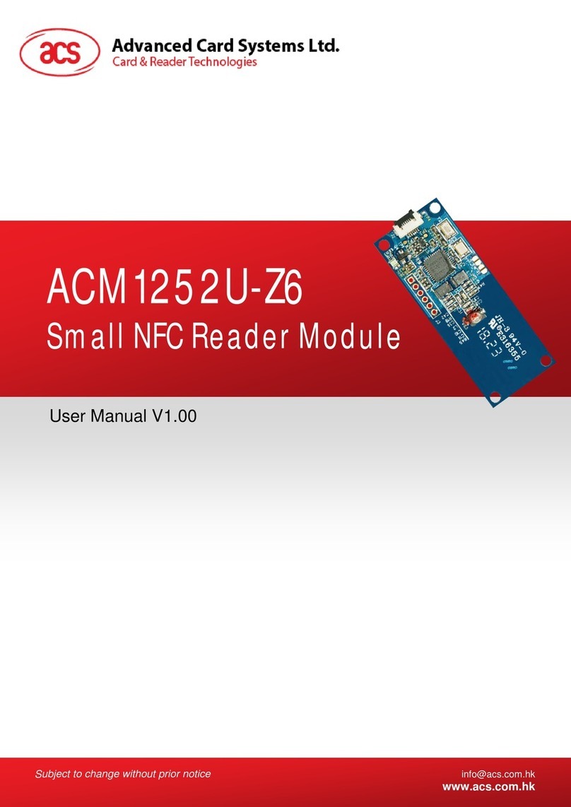
ACS ACM39U-Y User manual

www.acs.com.hk
User Manual V1.00
ACM39U-Y
Reader Module

Version 1.00 www.acs.com.hk
Page 2 of 14
www.acs.com
.hk
Table of Contents
1.0. Introduction .............................................................................................................3
2.0. Configuring the LED Operation Status..................................................................4
2.1. For ACM39U-Y3 (CCID)........................................................................................................4
2.1.1. Enable LED for Smart Card Operation Status..............................................................4
2.1.2. Enable LED for Power Status .......................................................................................4
2.1.3. LED Behaviors..............................................................................................................5
3.0. Connecting the ACM39U-Y to Another Device via USB........................................6
4.0. Configuring Card Detection....................................................................................8
5.0. Connecting to Card Insertion Signal......................................................................9
5.1. Connector Pin Details............................................................................................................9
5.2. Card Detection Pin Behaviors..............................................................................................10
5.3. Configure Card Detection Signal.........................................................................................10
6.0. Configuring Extended Card Connector ...............................................................11
7.0. Extending Power and Card Operation Status Signals........................................14
List of Figures
Figure 1 : ACM39U-Y3 LED Configuration ............................................................................................4
Figure 2 : ACM39U-Y USB Configuration..............................................................................................7
Figure 3 : ACM39U-Y Card Detection Configuration .............................................................................8
Figure 4 : ACM39U-Y Card Insertion Signal..........................................................................................9
Figure 5 : Card Detection Signal Pin Diagram .....................................................................................10
Figure 6 : ACM39U-Y Card Detection Signal Configuration ................................................................10
Figure 7 : ACM39U-Y Extended Card Connector Configuration..........................................................12
Figure 8 : ACM39U-Y External Card Connection Diagram..................................................................13
Figure 9 : ACM39U-Y Extended Power and Card Operation Status Signals ......................................14

Version 1.00 www.acs.com.hk
Page 3 of 14
www.acs.com
.hk
1.0.Introduction
The ACM39U-Y provides a solution for secured access control by employing the globally recognized
ACR39 core. It comes in module form to enable easy implementation of smart card-based solutions in
embedded systems. The ACM39U-Y utilizes the latest microchip technology, bringing you high
security for your confidential files in a convenient and easy way. The ACM39U-Y comes in two
variants: CCID and non-CCID.
This document is a guide to the use and configuration of the various connectors of the ACM39U-Y, so
that users can maximize its convenience and adaptability in various embedded environments.

Version 1.00 www.acs.com.hk
Page 4 of 14
www.acs.com
.hk
2.0.Configuring the LED Operation Status
2.1. For ACM39U-Y3 (CCID)
There are two LEDs on the ACM39U-Y3 that display its operation status:
Red is for power
Green is for smart card operation
Figure 1: ACM39U-Y3 LED Configuration
2.1.1. Enable LED for Smart Card Operation Status
To enable the LED for smart card operation status (see D2), connect a jumper to (J5) (see Figure 1).
2.1.2. Enable LED for Power Status
To enable the LED for power status (see D3), connect a jumper to (J6) (see Figure 1).

Version 1.00 www.acs.com.hk
Page 5 of 14
www.acs.com
.hk
2.1.3. LED Behaviors
The table below shows the behaviors of the LEDs during card polling.
LED Color
Behavior
Status
Red
On
Power
Green
Slow flash1
No card present/
Card power off
On
Card power on
Fast flash
Card operation
1
The LED turns on for 200 ms every 2 seconds.

Version 1.00 www.acs.com.hk
Page 6 of 14
www.acs.com
.hk
3.0.Connecting the ACM39U-Y to Another Device via USB
The ACM39U-Y has a USB port that can be used to connect the module to another device.
To do this:
Option 1: Connect socket (J4) via USB cable to another peripheral device (see Figure 2).
1USB VCC
2USB D-
3USB D+
4USB GND
5USB shielding
Option 2: Connect jumper (J8) via USB pinout to another peripheral device (see Figure 2).
1, 3, 4USB GND
2USB D+
5USB D-
6USB VCC
Note: Do not connect both J4 and J8 at the same time as it may cause abnormal behavior.

Version 1.00 www.acs.com.hk
Page 7 of 14
www.acs.com
.hk
Figure 2: ACM39U-Y USB Configuration

Version 1.00 www.acs.com.hk
Page 8 of 14
www.acs.com
.hk
4.0.Configuring Card Detection
There are two types of card detection:
Normal Open
Normal Closed
Since the ACM39U-Y offers an extendable smart card connector signal, you can choose the type of
card detection to be used on the other end of the device.
To choose a type of card detection:
1. Connect a jumper in (J3).
Note: This setting is dedicated for extended smart card connectors. By default, the ACM39U-
Y card connector is Normal Open.
The table below shows the two types of card detection and their corresponding jumper connections.
Configuration
Connection
diagram
Descriptions
Normal open card
detection circuit
Connect the two pins shown in red for normal
open card detection
Normal closed card
detection circuit
Connect the two pairs of pins shown in red for
normal closed card detection.
Figure 3: ACM39U-Y Card Detection Configuration

Version 1.00 www.acs.com.hk
Page 9 of 14
www.acs.com
.hk
5.0.Connecting to Card Insertion Signal
The card insertion signal can be used for the buzzer.
The pin diagram in green is the connection that includes the card detection pin and GND.
Figure 4: ACM39U-Y Card Insertion Signal
5.1. Connector Pin Details
You can make use of pin 1 and pin 6 of J2 to get the signal of card insertion. When a card is inserted
to the ACM39U-Y, pin 6 will be connected to GND.
1GND 6Card detection pin

Version 1.00 www.acs.com.hk
Page 10 of 14
www.acs.com
.hk
5.2. Card Detection Pin Behaviors
The table below shows the behavior of the card detection pin.
Card Status
Behavior
Card inserted
Connected to GND
Card removed
Floating
5.3. Configure Card Detection Signal
To get the card detection signal in (J2), connect a jumper in (J3) as shown in the connection diagram.
Figure 5: Card Detection Signal Pin Diagram
Note: This setting means that the ACM39U-Y card connector is set to Normal Open as mentioned in
the section Configuring Card Detection. If Normal Closed card detection is set, the behaviors
indicated in the section Card Detection Pin Behaviors are reversed.
Figure 6: ACM39U-Y Card Detection Signal Configuration

Version 1.00 www.acs.com.hk
Page 11 of 14
www.acs.com
.hk
6.0.Configuring Extended Card Connector
The ACM39U-Y is designed to offer an extendable smart card connector signal that will best fit the
embedded system. The ACM39U-Y may be connected to another device that is equipped with a
smart card connector to interface with the smart card.
Notes:
1. Normal open or normal closed should be set if an extended smart card connector is being
used.
2. The extended card connector and the on-board card connector cannot be used at the same
time.
To extend the smart card connector signal to another peripheral:
1. Connect a jumper to (J2).
1GND 6Card detection pin
2GND (C5) 7Card VCC (C1)
3NC (C6) 8Card reset pin (C2)
4Card I/O (Data input/output) (C7) 9Card clock signal (C3)
5Card contact (C8) 10 Card contact (C4)

Version 1.00 www.acs.com.hk
Page 12 of 14
www.acs.com
.hk
Figure 7: ACM39U-Y Extended Card Connector Configuration
To use the external card connector, the selection resistor jumper should be changed. The resistor
array should be soldered on R14 instead of R15.

Version 1.00 www.acs.com.hk
Page 13 of 14
www.acs.com
.hk
Figure 8: ACM39U-Y External Card Connection Diagram

Version 1.00 www.acs.com.hk
Page 14 of 14
www.acs.com
.hk
7.0.Extending Power and Card Operation Status Signals
Aside from the smart card connector’s signal, the LED status for power and card operation can be
extended to other peripherals as well.
To do this:
1. Connect a jumper to (J9)and (J10)for the LED status of power and card signals.
1USB VCC 1USB VCC
2Not connected 2Not connected
3Connected signal from the MCU 3GND
Figure 9: ACM39U-Y Extended Power and Card Operation Status Signals
J9
J10
Table of contents
Other ACS Control Unit manuals
Popular Control Unit manuals by other brands

Emhart Teknologies
Emhart Teknologies Tucker TMP Series Programming manual

SCHUNK
SCHUNK RM-W Series Assembly and operating manual

Weco
Weco 14K3-XP Installation and user manual

Samson
Samson 2412 Series Mounting and operating instructions

Sony
Sony DSBK-100 operating instructions

EOS
EOS ECON F1 Assembly and operating instructions

Texas Instruments
Texas Instruments TLC694 Series Technical reference manual

Argo-Hytos
Argo-Hytos PRM7 Series instructions

Emerson
Emerson Fisher 92C installation guide

Asus
Asus AAEON MIPICSI Camera RVP Converter Kit user manual

Ebyte
Ebyte E31-400M17S manual

Fibocom
Fibocom L610 MiniPCIe Series Hardware guide