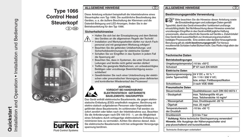
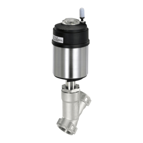
Burkert 8681 User manual

www.burkert.com
We reserve the right to make
technical changes without notice.
Technische Änderungen
vorbehalten.
Sous réserve de modifications
techniques.
© 2010 - 2011 Bürkert Werke GmbH
Operating Instructions
1105/02_EU-ml_00806166
/ Original DE
Type 8681
Control Head
Steuerkopf
Tête de commande
Quickstart
2
THE QUICKSTART1.
WARNING!
Important safety information!
Read quickstart carefully and thoroughly. Study in par-
ticular the chapters entitled 4. Basic Safety Instructions
and 3. Authorized use.
The operating instructions must be read and understood.•
Quickstart explains, for example, how to install and start-up
the device.
The detailed description of the device can be found in the
operating instructions for Control Head Type 8681.
The operating instructions can be found on the
Internet at:
www.burkert.com Documentation Type 8681
english
3
SYMBOLS2.
The following symbols are used in these instructions.
DANGER!
Warns of an immediate danger!
Failure to observe the warning will result in a fatal or• serious injury.
WARNING!
Warns of a potentially dangerous situation!
Failure to observe the warning may result in serious• injuries or death.
CAUTION!
Warns of a possible danger!
Failure to observe this warning may result in a moderate• or minor injury.
NOTE!
Warns of damage to property!
Important tips and recommendations for safe and
the flawless functioning of the device.
designates a procedure which you must carry out.
english

4
3. AUTHORIZED USE
Non-authorized use of the Control Head Type 8681
may be a hazard to people, nearby equipment and
the environment.
The Control Head has been designed for use as• actuation of pneumatically operated process valves
and / or for recording the switching states of these.
Use according to the authorized data, operating condi-• tions and conditions of use specified in the contract
documents and operating instructions.
In view of the large number of options for use it might• be necessary to test prior to installation whether the
control head is suitable for the concrete use.
If you have any questions, please contact your Bürkert
Service Center.
The device may be used only in conjunction with third-• party devices and components recommended and
authorized by Burkert.
Any unauthorized reconstructions and changes to the• control head are prohibited for safety reasons.
Correct transportation, correct storage and installation• and careful use and maintenance are essential for
reliable and faultless operation.
For connecting the control head, use line installations• that do not cause any mechanical stresses.
Use the device only as intended.•
english
5
Predictable Misuse3.1.
Do not supply the medium connectors of the system with•
aggressive or flammable media.
Do not supply the medium connectors with any liquids.•
Do not physically stress the housing (e.g. by placing objects•
on it or standing on it, or using it as attachment point for
transport work).
Do not make any external modifications to the device•
housings. Do not paint the housing parts or screws.
In the explosion-risk area, only wipe the control head with a•
damp or anti-static cloth to avoid electro-static charges!
english
6
4. BASIC SAFETY
INSTRUCTIONS
These safety instructions do not make allowance for any
contingencies and events which may arise during the instal-•
lation, operation and maintenance of the devices.
local safety regulations - the operator is responsible for•
observing these regulations, also with reference to the
installation personnel.
DANGER!
Danger – high pressure!
Before loosening pneumatic lines and valves, turn off• the pressure and vent the lines.
Danger of explosion in explosive atmosphere (only in
the event of a fault as zone 2)!
Opening the hood or the housing in an explosive atmo-• sphere is only allowed in the isolated state!
WARNING!
Risk of electric shock!
Before reaching into the system (except for the• Teach-In procedure in a non-explosive atmosphere)
switch off the power supply and secure it to prevent
english
7
restarting!
Observe applicable accident prevention and safety• regulations for electrical equipment!
WARNING!
General Hazardous Situations.
To prevent injuries, ensure that:
the system cannot be activated unintentionally.•
installation and maintenance work, as well as operator• control actions may be carried out by authorized, quali-
fied technicians only and with the appropriate tools.
after an interruption in the power supply or pneu-• matic supply, ensure that the process is restarted in a
defined or controlled manner.
the device may be installed and operated only when in• perfect condition and in consideration of the operating
instructions.
the general rules of technology apply to application• planning and operation of the device.
english
Type 8681

8
NOTE!
Electrostatic sensitive components / modules!
The device contains electronic components, which react•
sensitively to electrostatic discharge (ESD). Contact
with electrostatically charged persons or objects may
be hazardous to these components. In the worst case
scenario, they will be destroyed immediately or will fail
after start-up.
Observe the requirements in accordance with DIN EN•
61340-5-1 and 5-2 to minimize or avoid the possibility of
damage caused by sudden electrostatic discharge!
Also, ensure that you do not touch electronic components•
when the power supply voltage is present!
Control Head Type 8681 was developed with due
consideration given to accepted safety rules and
is state-of-the-art. Nevertheless, dangerous situa-
tions may occur.
Failure to observe this operating manual and its oper-
ating instructions as well as unauthorized tampering with
the device release us from any liability and also invalidate
the warranty covering the devices and accessories!
english
9
Explosive Atmosphere4.1.
NOTE!
Operation of the Control Head in Explosive
Atmosphere
The housing may not be opened when devices are•
charged! It should be secured against unintentional
opening using plastic self-cutting screws or seal (or
comparable)!
Layers of dust on the housing may not exceed 5 mm!•
Lint, conductive and non-conductive dust particles are
allowed.
The inside of the housing may not be dirty!
Activating the DIP switches on the circuit board, using•
the service plug and the Teach buttons is not allowed in
explosive atmosphere!
english
10
GENERAL INFORMATION5.
Scope of Supply5.1.
Check immediately upon receipt of the delivery that the con-
tents are not damaged and that the type and scope agree
with the delivery note and packing list.
If there are any discrepancies, please contact us immedi-
ately.
Contact address5.2.
Germany:
Bürkert Fluid Control Systems
Sales Center
Christian-Bürkert-Straße 13-17
D-74653 Ingelfingen
Tel.: +49 7940 10 91 111
Fax: +49 7940 10 91 448
E-mail: [email protected]
International:
The contact addresses can be found on the Internet at:
www.burkert.com Bürkert Company Locations
english
11
STRUCTURE AND FUNCTION6.
The Control Head Type 8681 has been designed for use
as actuation of pneumatically operated process valves and/
or for recording the switching states of these.
For the recording and feedback of the process valve
switching positions to a higher-level control, the control
head has been equipped with a contactless position mea-
suring system, which works with three discrete, adjustable
feedback signals (Teach-In Function).
Various pneumatic and electrical connection variants are
available.
Positions and status information can be indicated by means
of three signal colors.
Manual Control6.1.
Standardly, the control head provides the following:
a magnetic manual control that is easily accessible from•
the outside on the basis of encoded magnetic fields for
Solenoid Valve 1 (Connection 2/A1), as well as
a mechanical manual control accessible when the hood•
is open on each equipped solenoid valve.
english
Type 8681

12
Structure6.2.
Pneumatic
connections
Locking/(shoulder) screws
as protection against pulling
off from the hub flange
Electrical
connections
(Cable
glands)
Sealing lug
Electronics module
(24VDC- or AS-i-
Design with service
interface, connection
terminals, DIP, Teach-
In-buttons)
Position measuring system with LED’s
Flow restriction
screw(s) of
solenoid valves
Mechanical
manual control
at solenoid
valves (red
levers)
english
13
TECHNICAL DATA7.
Operating Conditions7.1.
Ambient temperature: -10 ... +55 °C
Protection class: IP65 / IP67 according to EN 60529 or
IP69K according to IEC 40050-9
Mechanical Data7.2.
Dimensions: see data sheet
Housing material: outside: PA, PP, PPO, VA
inside: ABS, PA, PMMA
Sealing material: outside: CR, EPDM
inside: EPDM, FKM, NBR
Pneumatic Data7.3.
Control medium: Oil-free and dry air, neutral gases,
Quality classes in accordance with
DIN ISO 8573-1 (5 µm filter
recommended)
Dust content: max. particle size 40 µm,
(quality class 5) max. particle density 10 mg/m3
Water content: max. pressure dew point -20 °C or
(quality class 3) min. 10 °C below the lowest
operating temperature
english
14
Oil content: max. 25 mg/m3
(quality class 5)
Temperature range
of compressed air: -10 to +50 °C
Pressure range: 2.5 to 8 bar
Air rate of solenoid
valve: 110 IN/min (for de-/aeration, ventilation)
(110 IN/min - supplied state
200 IN/min - maximum typical flow-rate)
(QNn value according to definition for
pressure drop from 7 to 6 bar absolute
at +20 °C)
Connections: Intake and exhaust air connection G1/4
Working connections G1/8
Position Measuring System Data7.4.
Stroke range: 0 ... 80 mm (measuring range)
Resolution: 0.1 mm
Total fault:
± 0.5 mm - when using a target as
mentioned in the manual
Electrical Data7.5.
see chapter 9. 24 V DC - Design or 10. AS-I - Design or
11. DeviceNet- Design or 12. 120 V AC - Design.
english
15
ASSEMBLY / INSTALLATION8.
DANGER!
Risk of injury from high pressure in the equipment!
Before loosening pneumatic lines and valves, turn off• the pressure and vent the lines.
WARNING!
Risk of injury due to electrical shock!
Before reaching into the system (except for the• Teach-In procedure in a non-explosive atmosphere)
switch off the power supply and secure it to prevent
restarting!
Observe applicable accident prevention and safety• regulations for electrical equipment!
Risk of injury from improper installation!
Installation may be carried out by authorized techni-• cians only and with the appropriate tools!
Risk of injury from unintentional activation of the
system and an uncontrolled restart!
Secure system from unintentional activation.•
Following assembly, ensure a controlled restart.•
english
Type 8681

16
Assembly8.1.
For the installation of the Control Head Type 8681 to a
process valve, you will require a process valve-specific hub
flange as an adapter. The hub flange must be adapted to
the design of the process valve.
Mount the piston rod with the target on the process
valve spindle. Observe reference dimensions!
Fasten the hub flange on the process valve.
During this, observe central alignment and sealing
conditions!
Check the secure fit of the sealing rings (in the upper
and lower grooves).
Mount the control head on the hub flange (seamlessly
360° rotatable).
Secure the control head with the two locking screws
(shoulder screws M5) in the middle grove of the hub
flange (see operating instructions).
Pneumatic Installation8.2.
Connect the required working connections 2/A1 to 2/
A3 (each according to model) with the corresponding
connections on the process valve.
Connect the supply line to supply pressure connection
1/P (2.5 to 8 bar).
english
17
A silencer has already been mounted on the Exhaust
Air Connection (3/R) in the supplied state.
1/P
Supply pressure
connection
3/R
Exhaust air
connection
(Silencer)
2/A3: SV 3 2/A2: SV 2 2/A1: SV 1
2/A1 ... A3 - Working connections - Solenoid valves (SV)
Sealing lugs
at the
housing
The flow restriction screws
R and P of the solenoid valves
(see operating instructions) are
used for setting the air intake and
exhaust for the working connec-
tions (for setting of the control
speed of the process valves).
R
P
open close
english
18
Opening and Closing the8.3.
Housing
Opening:
Loosen plastic self-cutting screws or seal, if housing
has been secured.
Open the plastic hood by turning counterclockwise (all
the way, approx. 1.5 cm).
Closing:
Put the plastic hood on the lower part such that the
inner lugs are positioned over the fastening grooves
and the external sealing lugs are positioned almost over
each other. Press the hood completely over the seal of
the lower part.
Turn the hood by approx. 1.5 cm clockwise (meaning
until the sealing lugs are positioned over each other).
A seal or a hood safeguard using plastic self-cutting
screws is required in the explosion-risk area!
Electrical Installation8.4.
see chapter
9. 24 V DC - Design, 10. AS-I - Design,
11. DeviceNet- Design or 12. 120 V AC - Design.
english
19
9. 24 V DC - DESIGN
Connection options9.1.
left: 1 x M16 x 1,5 cable
gland
for power supply and
signals
left: 1 x M16 x 1,5 cable
gland with multi-pole
connection (M12 plug
according to IEC 61076-
2-101, 12-pole) on a cable
of 8 cm length
right: 1 x M16 x 1,5 cable
gland for external initiator
right: 1 x M16 x 1,5 cable
gland for external initiator
english
Type 8681

20
Electrical Data9.2.
Power supply: 12 ... 28 V DC, residual ripple 10 %
Power consumption:
(standby current): 30 mA at 24 V DC
Solenoid valves:
Power input per max. 0.8 W
solenoid valve: (0.9 W during activation)
Operating mode: Long-term operation (100 %)
Central display of the
switching states: 42 mA with a power supply of
24 V DC per illuminated display;
Outputs/binary
feedback signals: S1 out - S4 out
Design: Normally open contact, PNP output
short-circuit-proof, with self-clocking
short-circuit protection
Switchable
output current: max. 100 mA per feedback signal
Option: Analog feedback signal:
Signal output: S3 out (binary feedback signal
S3out not available)
Type: Current source (4 to 20 mA)
english
21
Input / proximity switches (external initiator: S4 in):
Power supply:
Voltage present at control head - 10 %
Current carrying
capacity, sensor
power supply: max. 90 mA;
short-circuit protection
Design: DC 2- and 3-conductor, NO or NC
(factory setting NO), PNP output
Valve control inputs (Y1 - Y3):
Signal level - active: U > 10 V, max. 24 V DC + 10 %
Electrical Installation9.3. (24 VDC)
WARNING!
Risk of injury due to electrical shock!
Before reaching into the system (except for the• Teach-In procedure in a non-explosive atmosphere)
switch off the power supply and secure it to prevent
restarting!
Observe applicable accident prevention and safety• regulations for electrical equipment!
Risk of injury from improper installation!
Installation may be carried out by authorized techni-• cians only and with the appropriate tools!
english
22
Cable glands:
Open the housing.
Assemble connection cables for signals and power
supply as well as for the external initiator.
Insert cables through the respective cable glands into
the interior of the housing.
Secure the wires to the terminal strips according to the
pin assignments depicted in the figure.
Solenoid valve
connection
with status
LED for SV1
Terminal strip 1
Service
interface
DIP switches
for color
coding the
LED‘s
Terminal strip 2
(for external
initiator)
Teach-In-
buttons T1-3
SV-connections
with status LED
for SV2, 3
english
23
Terminal strip 1 Configuration
24 V Power supply 24 V
GND GND
S1 OUT Output position 1
S2 OUT Output position 2
S3 OUT Output position 3
(Option: analog signal)
S4 OUT Output external initiator
Y1 Input solenoid valve 1
Y2 Input solenoid valve 2
Y3 Input solenoid valve 3
Terminal strip 2 Configuration
24 V Power supply 24 V for external
initiator
S4 IN Input external initiator
GND GND external initiator
Close the housing
.
Ensure IP protection(dummy plugs)!
english
Type 8681

24
Cable gland with Multi-pole connection:
Internal cabling work is not required for models with multi-pole
connection. But you will require the correspondingly
assembled cable sets with the following pin assignments:
Pin Description Configuration
1 24 V Power supply 24 V
2 GND GND
3 S1 OUT Output position 1
4 S2 OUT Output position 2
5 S3 OUT Output position 3
(Option: analog signal)
6 S4 OUT Output external initiator
7 Y1 Input solenoid valve 1
8 Y2 Input solenoid valve 2
9 Y3 Input solenoid valve 3
10-12 not used
An external initiator can be connected using the small 3-pin
terminal strip 2 (see figure on page 22 or manual, chapter
„Connection of an external initiator“).
english
25
Input and output signals to the higher-level control (PLC):
Pin 9 - Y3
Pin 8 - Y2
12
Pin 6 - S4 out
Pin 7 - Y1
Pin 1 - 24 V
Pin 5 - S3 out
Pin 4 - S2 out
11
Pin 3 - S1 out Pin 2 - GND
10
(12-pole circular plug-in connector M12 x 0.75 - male,
acc. to IEC 61076-2-101 — view onto the plug pins)
english
26
10. AS-I - DESIGN
Connection options10.1.
left connection:
1 x M16 x 1,5 cable gland with Multi-pole connection
(M12 plug according to IEC 61076-2-101, 4-pole) on a
cable of 8 or 80 cm length
right connection:
1 x M16 x 1,5 cable gland for external initiator
Maximum Length of the Bus10.2.
Line
The bus cable may be a maximum of 100 m long. When
designing the system, consider the length of the round cable
leading directly to the control head (see example calculation
in the operating instructions).
english
27
Number of Connectable10.3.
Control Heads
In AS interface versions with extended addressing range
(A/B slave), 1 master can communicate with 62 slaves.
In AS interface versions with addressing range 31 slaves a
maximum of 31 control heads can be connected to a bus line
(the address range restriction).
10.4. Electrical Data
Power supply:
Standard: via AS-i
(29,5 ... 31,6 V DC
acc. specification)
Option: externally
(19,2 V DC to 31,6 V DC)
Setting the valve’s power supply using jumpers on the
AS-interface electronics module.
Input / proximity switches (external initiator: S4 in):
Power supply: AS interface voltage present at
control head - 10 %
english
Type 8681

28
Current carrying capacity,
sensor power supply: max. 30 mA;
short-circuit protection
Design: DC 2- and 3-conductor, NO or
NC (factory setting NO), PNP
output
Inputs (from master
perspective):3 binary feedback signals and
external initiator
Outputs (from master
perspective): 0 to 3 solenoid valves
Switching capacity: max. 0.8 W via AS interface
Pull-in current: 30 mA or 0.9 W / 200 ms
Operating mode: Long-term operation (100 %)
Central display of the switching states:
Power consumption: max. 33 mA or 1 W per illumi-
nated display (at 30.5 V AS-
interface voltage)
Power supply via AS interface bus:
Power consumption
from AS interface: max. 200 mA (incl. external
initiator with 30 mA)
Integrated short-circuit protection
english
29
External Power Supply:
Ext. power supply: 19.2 V DC to 31.6 V DC
Max. power consumption
from external power supply: 110 mA at 24 V DC
Integrated short-circuit protection
Electrical Installation (AS-i)10.5.
WARNING!
Risk of injury due to electrical shock!
Before reaching into the system (except for the• Teach-In procedure in a non-explosive atmosphere)
switch off the power supply and secure it to prevent
restarting!
Observe applicable accident prevention and safety• regulations for electrical equipment!
Risk of injury from improper installation!
Installation may be carried out by authorized techni-• cians only and with the appropriate tools!
Internal cabling work is not required for any of the AS Interface
designs with multi-pole connection. However, you will require
the correspondingly assembled cable sets with the following
pin assignments.
english
30
Pin 2
Pin 3 Pin 1
Pin 4
Likewise, the jumpers on the electronics module must be set
correspondingly (power supply via AS-i or externally) - see
page 27.
Power supply
Pin
(via AS-i)
Configuration
(externally)
Configuration Color
1 AS-i+ AS-i+ brown
2 not used GND white
3 AS-i- AS-i- blue
4 not used 24 V+ black
An external initiator can be connected using the small
3-pin terminal strip 2 - see manual, chapter „Connection of
an external initiator“.
english
31
11. DEVICENET- DESIGN
Connection11.1.
left connection:
1 x M16 x 1,5 cable gland with Multi-pole connection
(M12 plug according to IEC 61076-2-101, 5-pole) on a
cable of 80 cm length
right connection:
1 x M16 x 1,5 cable gland for external initiator
DeviceNet Specification11.2.
EDS file 8681.EDS
Icons 8681.ICO
Baud rate Factory setting: 125 kBit/s
Address Factory setting: 63
english
Type 8681

32
Process data 2 static input assemblies
(Input: from the control head to the
DeviceNet Master/Scanner)
1 static output assembly
Inputs 3 discrete feedback signals of the posi-
tion measuring system (pos. S1 - S3)
1 discrete feedback signal of the
external initiators (S4)
1 analog position signal in mm
Supply via DeviceNet string
(11 to 25 V DC)
Switch level high signal 5 V
Switch level low signal 1,5 V
Outputs 3 solenoid valves
Power consumption
from the bus: max. 5 W, (3 valves with each 0,8 W)
Length of the Bus line11.3.
The maximum total line length (sum of trunk lines and drop
lines) of a network depends on the baud rate.
The maximum total line length (according to DeviceNet
specification) is for:
english
33
Baud rate Thick Cable Thin Cable
125 500 m 100 m
250 250 m 100 m
500 100 m 100 m
The maximum drop line length is for:
Baud rate Drop Line Sum (in Network)
125 6 m 156 m
250 6 m 78 m
500 6 m 39 m
Electrical Data11.4.
Electrical power supply: 11 to 25 V DC (according to
specification)
Max. power consumption: 200 mA at 24 V DC
Input / proximity switches (external initiator: S4 in):
Power supply: via DeviceNet power
supply - 10 %
Current carrying capacity
sensor power supply: max. 30 mA
Short-circuit protection
Design: DC 2- and 3-conductor,
NO contact, PNP output
english
34
Input current 1 signal: ISensor > 6.5 mA, limited
internally to 10 mA
Input voltage 1 signal: USensor > 10 V
Input current 0 signal: ISensor < 4 mA
Input voltage 0 signal: Usensor< 5 V
Inputs (from master perspective) / binary or analog
feedback signals:
The recovery of the 3 valve positions reported back binarily
or of the analog position signalis described in the manual,
chapter “Position Mesuring System”.
Outputs (from master perspective) / solenoid valves:
max. switching capacity 1.0 W
typ. continuous output 0.8 W
Output reduction integrated via DeviceNet
interface electronics
pull-in current 120 mA typ. / 200 ms
(3 valves)
Holding current 100 mA typ. at 24 V DC
(3 valves)
Operating mode Long-term operation
(100 % operation)
Valve types 6524
Central display of the switching states:
Power consumption from
DeviceNet at 24 V DC 42 mA with 24 V DC power
english
35
supply per illuminated display
shown; Color switching see
in the manual, chapter “LED -
Color Assignments”
Electrical Installation (DVN)11.5.
WARNING!
Risk of injury due to electrical shock!
Before reaching into the system (except for the• Teach-In procedure in a non-explosive atmosphere)
switch off the power supply and secure it to prevent
restarting!
Observe applicable accident prevention and safety• regulations for electrical equipment!
Risk of injury from improper installation!
Installation may be carried out by authorized techni-• cians only and with the appropriate tools!
No internal cabling work is required for any of the Devi-
ceNet designs.
However, you will require the correspondingly assembled
cable sets with the pin assignments described below:
english
Type 8681

36
Pin 4: CAN_H
Pin 5: CAN_L
Pin 1: Drain
Pin 3: V–
Pin 2: V+
View of plug from the front onto the pins:
Pin Signal Color
1 Drain (shield)
2 V+ red
3 V- black
4 CAN_H white
5 CAN_L blue
An external initiator can be
connected using the small
3-pin terminal strip - see
manual, chapter „Connection
of an external initiator“.
english
37
Network Topology11.6.
When installing a DeviceNet system, ensure that the termi-
nating circuit of the data lines is correct. The circuit prevents
the occurrence of interference caused by signals reflected
onto the data lines.
The trunk line must be terminated at both ends with
resistors of 120 Ωand 1/4 W power loss (see the manual,
chapter „Network Topology of a DeviceNet System“).
Configuring the Baud rate11.7.
and DVN address
8 DIP switches are available for configuration:
DIP switches 1 to 6 for DeviceNet address•
(factory setting: 63, i.e. DIP 1 - 6: on)
DIP switches 7 to 8 for Baud rate•
(factory setting: 125, i.e. DIP 7 + 8: off)
Further configuring - see manual, chapter „Configuring the
DeviceNet address / baud rate“
english
38
Configuration of Process Data11.8.
To transmit process data via an I/O connection, 2 static
input and 1 static output assembly can be selected, see
manual, chapter “Configuration of Process Data”
„Address“ in the table describes the data attribute of the
assemblies for read access (class, instance, attributes).
Input-
Assemblies
Address Format of the Data attribute
value 0: OFF / value 1: ON
S1…S4
(factory
setting)
4, 1, 3 Byte 0:
Bit 0: position S1
Bit 1: position S2
Bit 2: position S3
Bit 3: position S4
S1…S4 +
POS
(with POS:
current
position)
4, 2, 3 Byte 0:
Bit 0: position S1
Bit 1: position S2
Bit 2: position S3
Bit 3: position S4
Bit 4…7: not used
Byte 1:
POS in mm
„Address“ in the table describes the data attribute of the
assemblies for read access (class, instance, attributes).
english
39
Output-
Assembly
Address Format of the Data attribute
value 0: OFF / value 1: ON
Solenoid
valve
SV 1 ... 3
4, 21, 3 Byte 0:
Bit 0: SV1
Bit 1: SV2
Bit 2: SV3
Bit 3…7: not used
Configuration of the Safety11.9.
Position of Solenoid Valves if
Bus Error
If the bus fails, the solenoid valve is switched to a program-
mable safety position (factory setting: the solenoid valve
is in the power-off-state) - for details see manual, chapter
„Configuration of the device“.
The bus status LED „Network“ on the electronic module
specifies the kind of error by color and blinking pattern - for
details see manual, chapter „Display of the Status LEDs in
the event of a bus error“).
english
Type 8681

40
120 V AC - DESIGN12.
Connection12.1.
left connection:
1 x M16 x 1,5 cable gland for
power supply and signals
right connection:
1 x M16 x 1,5 cable gland for
external initiator
Electrical Data12.2.
Central power supply: 110 ... 130 V AC, 50/60 Hz
Power consumption
(stnd-by current): 10 mA at 120 V AC
Solenoid valves:
power consumption
per solenoid valve: max. 1,4 VA
(1,7 VA during activation)
power consumption
per solenoid valve: 12 mA at 120 V AC
Operation mode: Long-term operation (100 %)
english
41
Central display of the switching states:
13 mA with a power supply of
120 V AC per illuminated display
Outputs/binary
feedback signals: S1out - S3out
Design: NO contact, L switching,
short-circuit protection via auto-
matically resetting fuse
switchable output
current: max. 50 mA per feedback signal
Output voltage
- active: (operating voltage - 2 V)
- inactive: max. 1 V in unloaded state
Feedback signal output:S4 out is directly connected to
S4 in
Input / proximity switches (external initiator: S4 in):
Power supply: voltage present at control head
UNominal = 120 V AC, 50/60 Hz
Current carrying capacity,
sensor power supply: max. 0.7 A
Short-circuit protection
Design: DC 2- and 3-conductor,
NO contact, L-switching
input current 1-Signal: ISensor < 2 mA
english
42
Valve control inputs (Y1 - Y3):
Signal level - active: U > 60 V AC
Signal level - inactive: U < 20 V AC
Impedance: > 40 kOhm
Electrical Installation12.3.
WARNING!
Risk of injury due to electrical shock (120 V AC)!
When setting the position measuring system• (Teach-In), do not contact any live components!
Before reaching into the system (except for the• Teach-In procedure in a non-explosive atmosphere)
switch off the power supply and secure it to prevent
restarting
Observe applicable accident prevention and safety• regulations for electrical equipment!
Risk of injury from improper installation!
the• PE connection must be connected!
Installation may be carried out by authorized techni-• cians only and with the appropriate tools!
english
43
Cable gland:
Open the housing.
Assemble connection cables for signals and power
supply as well as for the external initiator.
Insert cables through the respective cable glands into
the interior of the housing.
Connect the wires to the connection terminals
according to the pin assignment described in the
figure. Fix them.
connection
for valve 1
with status
LED
terminal
strip 1
service
interface
DIP-switches
for color
coding the
LED‘s
terminal strip 2
(external
initiator)
Teach-In-
buttons
T1-3
connections for
valve 2, 3 with
status LED
english
Type 8681

44
Terminal strip 1 Configuration
PE Protection Earth - protective conductor
LPower supply
120 V AC
live conductor
N neutral conductor
S1 OUT Ouput position 1
S2 OUT Ouput position 2
S3 OUT Ouput position 3
S4 OUT Ouput external initiator
Y1 Input solenoid valve 1
Y2 Input solenoid valve 2
Y3 Input solenoid valve 3
Terminal strip 2 Configuration (external initiator)
L Power supply - live conductor
S4 IN Input external initiator
N Power supply - neutral conductor
Close the housing.
Ensure IP protection (dummy plugs).
An external initiator can be connected using the small
3-pin terminal strip 2 - see manual, chapter „Connection of
an external initiator“.
english
45
POSITION MEASURING13.
SYSTEM
The recordable stroke range is between 0 and 80 mm.
Three Teach-In buttons have been provided for comparison
with the actual stroke range.
Teach-In13.1.
Open the housing.
Supply electrical power.
Position the process valve at the lower switching
position.
Depress the lower Teach-In button (T1) for approx. 1.5
seconds (the LED corresponding to this position will
flash quickly three times during the teaching phase).
Once this position has been stored, the corresponding
LED will remain continuously lit until the position of the
piston is changed.
Afterwards, position the process valve at the upper
switching position to be recorded.
Depress the upper Teach-In button (T2) for approx. 1.5
seconds (the LED corresponding to this position will
flash quickly three times during the teaching phase).
Once this position has been stored, the corresponding
LED will remain continuously lit until the position of the
piston is changed.
english
46
The process valve can now be moved into a third,
defined position.
Depress the middle Teach-In button (T3) for approx.
1.5 seconds (the LED corresponding to this position
will flash quickly three times during the teaching
phase).
Once this position has been stored, the corresponding
LED will flash continuously until the position of the
piston is changed.
If necessary, return control head and system to normal
state (switching position, power supply).
Close the housing.
Teach-Reset13.2.
Depress the Teach-In button (T1+T2) for ca. 2.5 sec.
(optical feedback: Blinking in the fault color)
Autotune13.3.
Autotune functions and Autotune sequences - see oper-
ating instructions.
LED - Color Assignments13.4.
S1 -green, continuously lit,
S2 -yellow, continuously lit,
S3 -green, continuously flashing (250 ms/250 ms)
(Delivered state of the DIP switches: 0000)
english
47
START-UP14.
WARNING!
Risk of injury from improper operation!
Improper operation may cause injury and damage to the
device and its environment.
Before starting-up must be ensured that the contents• of the manual operator is known and understood.
The safety instructions and the intended use must be• followed.
Only adequately trained personnel should take the• plant / the device in operation.
Assembly of the control head type 8681.
Pneumatic and electrical installation.
Setting the position measuring system (Teach-In).
After assembly, installation and setting of the position mea-
suring system according to the operating instructions the
control head is ready for operation.
english
Type 8681

48
PACKAGING, TRANSPORT,15.
STORAGE, DISPOSAL
NOTE!
Transport / storage damage!
Inadequately protected equipment may be damaged
during transport or storage.
Protect the device during transportation / storage• against moisture and dirt in shock-resistant packaging.
Avoid the effects of heat and cold which could result• in temperatures above or below the permitted storage
temperature.
Storage temperature: -20 ... +65 °C.•
NOTE!
Damage to the environment caused by device com-
ponents contaminated with media.
Observe the relevant disposal and environmental pro-• tection regulations.
Dispose of the device and packaging in an environmen-
tally friendly manner.
Observe national waste disposal regulations.
english
Type 8681

www.burkert.com
We reserve the right to make
technical changes without notice.
Technische Änderungen
vorbehalten.
Sous réserve de modifications
techniques.
© 2010 - 2011 Bürkert Werke GmbH
Operating Instructions
1105/02_EU-ml_00806166
/ Original DE
Typ 8681
Steuerkopf
Quickstart
Deutsch
50
DER QUICKSTART1.
WARNUNG!
Wichtige Informationen zur Sicherheit!
Lesen Sie den Quickstart sorgfältig durch. Beachten Sie
vor allem die Kapitel Grundlegende Sicherheitshinweise
und Bestimmungsgemäße Verwendung.
Der Quickstart muss gelesen und verstanden werden.•
Der Quickstart erläutert beispielhaft die Montage und Inbe-
triebnahme des Gerätes.
Die ausführliche Beschreibung des Gerätes finden Sie in
der Bedienungsanleitung für den Typ 8681.
Die Bedienungsanleitung finden Sie im Internet:
www.buerkert.de Dokumentation Typ 8681
deutsch
51
DARSTELLUNGSMITTEL2.
In dieser Anleitung werden folgende Darstellungsmittel
verwendet.
GEFAHR!
Warnt vor einer unmittelbaren Gefahr!
Bei Nichtbeachtung sind Tod oder schwere Verletzun-• gen die Folge.
WARNUNG!
Warnt vor einer möglicherweise gefährlichen Situation!
Bei Nichtbeachtung können schwere Verletzungen oder• Tod die Folge sein.
VORSICHT!
Warnt vor einer möglichen Gefährdung!
Nichtbeachtung kann mittelschwere oder leichte Verlet-• zungen zur Folge haben.
HINWEIS!
Warnt vor Sachschäden!
Wichtige Tipps und Empfehlungen.
markiert einen Arbeitsschritt den Sie ausführen müssen.
deutsch

52
BESTIMMUNGSGEMÄSSE3.
VERWENDUNG
Bei nicht bestimmungsgemäßem Einsatz des
Steuerkopfes Typ 8681 können Gefahren für Per-
sonen, Anlagen in der Umgebung und die Umwelt
entstehen.
Der Steuerkopf ist konzipiert für den Einsatz als An-• steuerung pneumatisch betätigter Prozessventile und /
oder für die Erfassung von deren Schaltzuständen.
Für den Einsatz sind die in den Vertragsdokumenten• und der Bedienungsanleitung spezifizierten zuläs-
sigen Daten, Betriebs- und Einsatzbedingungen zu
beachten.
Angesichts der Vielzahl von Einsatz- und Verwen-• dungsfällen muss vor dem Einbau geprüft und erfor-
derlichenfalls getestet werden, ob der Steuerkopf für
den konkreten Einsatzfall geeignet ist:
Wenden Sie sich bei Unklarheiten an Ihr Bürkert Ser-
vice Center.
Das Gerät nur in Verbindung mit von Bürkert empfoh-• lenen bzw. zugelassenen Fremdgeräten und -kompo-
nenten einsetzen.
Eigenmächtige Umbauten und Veränderungen am• Steuerkopf sind aus Sicherheitsgründen verboten.
Voraussetzungen für den sicheren und einwandfreien• Betrieb sind sachgemäßer Transport, sachgemäße
deutsch
53
Lagerung und Installation sowie sorgfältige Bedienung
und Instandhaltung.
Verwenden Sie für den Anschluss des Steuerkopfes• Leitungsinstallationen, die keine unzulässigen mecha-
nischen Belastungen verursachen.
Setzen Sie das Gerät nur bestimmungsgemäß ein.•
Vorhersehbarer Fehlgebrauch3.1.
Speisen Sie in die Medienanschlüsse des Systems keine•
aggressiven oder brennbaren Medien ein.
Speisen Sie in die Medienanschlüsse keine Flüssigkeiten•
ein.
Belasten Sie das Gehäuse nicht mechanisch (z.B. durch•
Ablage von Gegenständen, als Trittstufe oder als Befesti-
gungspunkt bei Transportarbeiten).
Nehmen Sie keine äußerlichen Veränderungen an den•
Gerätegehäusen vor. Gehäuseteile und Schrauben nicht
lackieren.
Im Ex-Bereich den Steuerkopf zur Vermeidung elektrosta-•
tischer Aufladungen nur mit einem feuchten oder antista-
tischen Tuch abwischen!
deutsch
54
GRUNDLEGENDE4.
SICHERHEITSHINWEISE
Diese Sicherheitshinweise berücksichtigen keine
Zufälligkeiten und Ereignisse, die bei Montage, Betrieb•
und Wartung der Geräte auftreten können.
ortsbezogenen Sicherheitsbestimmungen, für deren•
Einhaltung, auch in Bezug auf das Montagepersonal, der
Betreiber verantwortlich ist.
GEFAHR!
Gefahr durch hohen Druck!
Vor dem Lösen von Leitungen oder Ventilen den Druck• abschalten und Leitungen entlüften.
Explosionsgefahr in Ex-Atmosphäre (nur im Störfall,
da Zone 2)!
Das Öffnen der Haube bzw. des Gehäuses unter• Ex-Atmosphäre ist nur im spannungslosen Zustand
zulässig!
WARNUNG!
Gefahr durch elektrische Spannung!
Vor Eingriffen ins System (außer Teach-In-Vorgang in• Nicht-Ex-Atmosphäre) die Spannung abschalten, vor
deutsch
55
Wiedereinschalten sichern!
Die geltenden Unfallverhütungs- und Sicherheitsbe-• stimmungen für elektrische Geräte beachten!
WARNUNG!
Allgemeine Gefahrensituationen.
Zum Schutz vor Verletzungen ist zu beachten:
Dass die Anlage nicht unbeabsichtigt betätigt werden• kann.
Installations- und Instandhaltungsarbeiten sowie• Bedienhandlungen dürfen nur von autorisiertem,
qualifiziertem Fachpersonal mit geeignetem Werkzeug
ausgeführt werden.
Nach einer Unterbrechung der elektrischen oder pneu-• matischen Versorgung ist ein definierter oder kontrol-
lierter Wiederanlauf des Prozesses zu gewährleisten.
Das Gerät darf nur in einwandfreiem Zustand und unter• Beachtung der Bedienungsanleitung eingebaut und
betrieben werden.
Für die Einsatzplanung und den Betrieb des Gerätes• müssen die allgemeinen Regeln der Technik eingehal-
ten werden
deutsch
Typ 8681

56
HINWEIS!
Elektrostatisch gefährdete Bauelemente /
Baugruppen!
Das Gerät enthält elektronische Bauelemente, die gegen•
elektrostatische Entladung (ESD) empfindlich reagieren.
Berührung mit elektrostatisch aufgeladenen Personen
oder Gegenständen können diese Bauelemente
gefährden. Im schlimmsten Fall werden sie sofort zerstört
oder fallen nach der Inbetriebnahme aus.
Beachten Sie die Anforderungen nach DIN EN•
61340-5-1 und 5-2, um die Möglichkeit eines Schadens
durch schlagartige elektrostatische Entladung zu mini-
mieren bzw. zu vermeiden!
Achten Sie ebenso darauf, dass Sie elektronische Bau-•
elemente nicht bei anliegender Versorgungsspannung
berühren!
Der Steuerkopf Typ 8681 wurde unter Einbe-
ziehung der anerkannten sicherheitstechnischen
Regeln entwickelt und entspricht dem Stand der
Technik. Trotzdem können Gefahren entstehen.
Bei Nichtbeachtung dieser Bedienungsanleitung und ihrer
Hinweise sowie bei unzulässigen Eingriffen in das Gerät
entfällt jegliche Haftung unsererseits, ebenso erlischt die
Gewährleistung auf Geräte und Zubehörteile!
deutsch
57
Ex-Atmosphäre4.1.
HINWEIS!
Betrieb des Steuerkopfes in Ex-Atmosphäre
Das Gehäuse darf bei Geräten unter Spannung nicht•
geöffnet werden! Es ist mit Kunststoffschneidschrauben
oder Verplombung (oder Vergleichbarem) gegen unbe-
absichtigtes Öffnen zu sichern!
Staubschichten auf dem Gehäuse dürfen 5 mm nicht•
überschreiten! Es sind Flusen, leitfähige und nicht-
leitfähige Stäube zulässig.
Das Innere des Gehäuses darf nicht verschmutzt sein!
Das Betätigen der DIP-Schalter auf der Platine, die•
Nutzung des Service-Steckers und der Teach-Tasten
ist unter Ex-Atmosphäre nicht zulässig!
deutsch
58
ALLGEMEINE HINWEISE5.
Lieferumfang5.1.
Überzeugen Sie sich unmittelbar nach Erhalt der Sendung,
dass der Inhalt nicht beschädigt ist und in Art und Umfang mit
dem Lieferschein bzw. der Packliste übereinstimmt.
Bei Unstimmigkeiten wenden Sie sich bitte umgehend an
uns.
Kontaktadressen5.2.
Deutschland
Bürkert Fluid Control Systems
Sales Center
Christian-Bürkert-Str. 13-17
D-74653 Ingelfingen
Tel. + 49 (0) 7940 - 10 91 111
Fax + 49 (0) 7940 - 10 91 448
E-mail: [email protected]
International
Die Kontaktadressen finden Sie im Internet unter:
www.burkert.com Bürkert Company Locations
deutsch
59
AUFBAU UND FUNKTION6.
Der Steuerkopf Typ 8681 ist konzipiert für den Einsatz als
Ansteuerung pneumatisch betätigter Prozessventile und /
oder für die Erfassung von deren Schaltzuständen.
Zur Erfassung der Prozessventilschaltstellungen und deren
Rückmeldung an eine übergeordnete Steuerung ist der
Steuerkopf mit einem berührungslosen Wegmesssystem
ausgestattet, welches mit 3 einstellbaren diskreten Rück-
meldesignalen arbeitet (Teach-In-Funktion).
Es sind verschiedene pneumatische und elektrische
Anschlussvarianten verfügbar.
Positionen und Statusinformationen können mittels 3 Sig-
nalfarben angezeigt werden.
Handbetätigung6.1.
Der Steuerkopf stellt standardmäßig zur Verfügung:
eine leicht von außen zugängliche• magnetische Hand-
betätigung auf Basis codierter Magnetfelder für das
Magnetventil 1 (Anschluss 2/A1) sowie
eine bei geöffneter Haube zugängliche• mechanische
Handbetätigung an jedem bestückten Magnetventil.
deutsch
Typ 8681

60
Aufbau6.2.
Pneuma-
tische
Anschlüsse
Sicherungsschraube (Ansatzschraube)
gegen das Abziehen vom Aufnahmeflansch
Elektrische
Anschlüsse
(Kabelver-
schraubungen)
Verplombungs-
nase
Elektronikmodul
(24VDC- oder
AS-i-Ausführung mit
Serviceschnittstelle,
Klemmleisten, DIP,
Teach-In-Tasten)
Wegmesssystem mit LED‘s
Drossel-
schrauben der
Magnetventile
mechanische
Handbetätigung
am MV (roter
Hebel)
deutsch
61
TECHNISCHE DATEN7.
Betriebsbedingungen7.1.
Umgebungstemperatur: -10 ... +55 °C
Schutzart: IP65 / IP67 nach EN 60529 bzw.
IP69K nach IEC 40050-9
Mechanische Daten7.2.
Maße: siehe Datenblatt
Gehäusematerial: außen: PA, PC, PPO, VA
innen: ABS, PA, PMMA
Dichtungsmaterial: außen: CR, EPDM
innen: EPDM, FKM, NBR
Pneumatische Daten7.3.
Steuermedium: ölfreie und trockene Luft, neutrale Gase
Qualitätsklassen nach DIN ISO 8573-1
(Filter 5 µm empfohlen)
Staubgehalt max. Teilchengröße 40 µm,
(Qualitätskl. 5) max. Teilchendichte 10 mg/m3
Wassergehalt max. Drucktaupunkt -20 °C oder
(Qualitätskl. 3) min. 10 °C unterhalb der niedrigsten
Betriebstemperatur
deutsch
62
Ölgehalt (Qualitätskl. 5) max. 25 mg/m3
Temperaturbereich der Druckluft: -10 ... +50 °C
Druckbereich: 2,5 ... 8 bar
Luftleistung
Magnetventil: 110 IN/min (für Be-, Ent-, Anlüftung)
(110 IN/min - Lieferzustand
200 IN/min - max. typischer Durchfluss)
(QNn-Wert nach Definition bei Druck-
abfall von 7 auf 6 bar absolut
bei +20 °C)
Anschlüsse: Zu- und Abluftanschluss G1/4
Arbeitsanschlüsse G1/8
Daten Wegmesssystem7.4.
Hubbereich: 0 ... 80 mm
Auflösung: 0,1 mm
Gesamtfehler: ± 0,5 mm (bei Verwendung eines
geeigneten Targets)
Elektrische Daten7.5.
siehe Kapitel 9. 24 V DC - Ausführung,
10. AS-I - Ausführung,
11. DeviceNet - Ausführung und
12. 120 V AC - Ausführung.
deutsch
63
MONTAGE / INSTALLATION8.
GEFAHR!
Verletzungsgefahr durch hohen Druck in der Anlage!
Vor dem Lösen von Leitungen oder Ventilen den Druck• abschalten und Leitungen entlüften.
WARNUNG!
Verletzungsgefahr durch Stromschlag!
Vor Eingriffen ins System (außer Teach-In-Vorgang in• Nicht-Ex-Atmosphäre) die Spannung abschalten, vor
Wiedereinschalten sichern!
Die geltenden Unfallverhütungs- und Sicherheitsbe-• stimmungen für elektrische Geräte beachten!
Verletzungsgefahr bei unsachgemäßer Montage!
Die Montage darf nur autorisiertes Fachpersonal mit• geeignetem Werkzeug durchführen!
Verletzungsgefahr durch ungewolltes Einschalten
der Anlage und unkontrollierten Wiederanlauf!
Anlage vor unbeabsichtigtem Betätigen sichern.•
Nach der Montage einen kontrollierten Wiederanlauf• gewährleisten.
deutsch
Typ 8681

64
Montage8.1.
Zur Montage des Steuerkopfes Typ 8681 an ein Prozess-
ventil benötigen Sie einen prozessventilspezifischen Auf-
nahmeflansch als Adapter. Der Aufnahmeflansch muss der
Bauform des Prozessventiles angepasst sein.
Die Kolbenstange mit Target auf die Prozessventil-
spindel montieren. Referenzmaße beachten!
Aufnahmeflansch auf dem Prozessventil befestigen.
Dabei die Zentrierung und die Abdichtungsbedin-
gungen beachten!
Sitz der beiden Dichtungsringe (in oberster und
unterster Nut) prüfen.
Steuerkopf auf den Aufnahmeflansch montieren (stu-
fenlos 360° drehbar).
Steuerkopf mit den zwei Sicherungsschrauben (Ansatz-
schrauben M5) in der mittleren Nut des Aufnahmeflan-
sches sichern (siehe Bedienungsanleitung).
Pneumatische Installation8.2.
Die benötigten Arbeitsanschlüsse 2/A1 bis 2/A3 (je
nach Variante) mit den zugehörigen Anschlüssen des
Prozessventils verbinden.
Versorgungsleitung mit dem Versorgungsdruckan-
schluss 1/P (2,5 … 8 bar) verbinden.
deutsch
65
Am Abluftanschluss (3/R) ist im Lieferzustand bereits
ein Schalldämpfer montiert.
1/P
Versorgungs-
druckanschluss
3/R
Abluftanschluss
(Schalldämpfer)
2/A3: MV 3 2/A2: MV 2 2/A1: MV 1
2/A1 ... A3 - Arbeitsanschlüsse Magnetventile (MV)
Verplombungs-
nasen
am Gehäuse
Die Drosselschrauben der
Magnetventile R und P
(siehe Bedienungsanleitung)
dienen der Einstellung der Luft-
zufuhr und -abfuhr der Arbeits-
anschlüsse (für die Einstellung
der Stellgeschwindigkeit der
Prozessventile).
R
P
auf zu
deutsch
66
Öffnen/Schließen des8.3.
Gehäuses
Öffnen:
Kunststoffschneidschrauben oder Verplombung lösen,
falls Gehäuse gesichert.
Kunststoffhaube durch Drehen gegen den Uhrzei-
gersinn (bis Anschlag, ca. 1,5 cm) öffnen.
Schließen:
Kunststoffhaube so auf das Unterteil aufsetzen, dass
die inneren „Nasen“ über den Befestigungsnuten liegen
und die äußeren Verplombungsnasen fast übereinander
liegen. Haube vollständig über die Dichtung des Unter-
teiles drücken.
Drehen der Haube um ca. 1,5 cm im Uhrzeigersinn
(bzw. bis Verplombungsnasen übereinander liegen).
Im Ex-Bereich wird eine Verplombung bzw. eine
Sicherung der Haube mit Kunststoffschneid-
schrauben gefordert!
Elektrische Installation8.4.
siehe Kapitel 9. 24 V DC - Ausführung,
10. AS-I - Ausführung,
11. DeviceNet - Ausführung und
12. 120 V AC - Ausführung.
deutsch
67
9. 24 V DC - AUSFÜHRUNG
Anschlussmöglichkeiten9.1.
links: 1 x M16 x 1,5 Kabel-
verschraubung
für Spannungsversorgung
und Signale
links: 1 x M16 x 1,5
Kabelverschraubung mit
Multipolanschluss (M12-
Stecker nach IEC 61076-
2-101, 12-polig) an Kabel
von 8 cm
rechts: 1 x M16 x 1,5
Kabelverschraubung für
externen Initiator
rechts: 1 x M16 x 1,5
Kabelverschraubung für
externen Initiator
deutsch
Typ 8681

68
Elektrische Daten9.2.
Spannungs-
versorgung: 12 ... 28 V DC, Restwelligkeit 10 %
Stromaufnahme
(Ruhestrom): 30 mA bei 24 V DC
Magnetventile: Leistungsaufnahme je Magnetventil:
max. 0,8 W
(0,9 W beim Einschalten)
Betriebsart: Dauerbetrieb (100 % ED)
Zentrale Anzeige der Schaltzustände:
42 mA bei Spannungsversorgung
24 V DC je dargestellter Leucht-
anzeige
Ausgänge/binäre
Rückmeldesignale: S1 out - S4 out
Bauart: Schließer (normally open),
PNP-Ausgang; kurzschlussfest,
schaltbarer
Ausgangsstrom: max. 100 mA je Rückmeldesignal
Option: analoges Rückmeldesignal:
Signalausgang: S3 out (binäres Rückmeldesignal
S3out entfällt hierbei)
Typ: Stromquelle (4 ...20 mA)
deutsch
69
Eingang/Näherungsschalter (externer Initiator: S4 in):
Spannungs- angelegte Spannung am
versorgung: Steuerkopf - 10 %
Strombelastbarkeit
Sensorversorgung: max. 90 mA; Kurzschlussschutz
Bauart: DC 2- und 3-Draht, NO od. NC;
PNP-Ausgang
Eingänge Ventilansteuerung (Y1 - Y3):
Signalpegel - aktiv: U > 10 V, max. 24 V DC + 10 %
Elektrische Installation (24 V DC)9.3.
WARNUNG!
Verletzungsgefahr durch Stromschlag!
Vor Eingriffen ins System (außer Teach-In-Vorgang in• Nicht-Ex-Atmosphäre) die Spannung abschalten, vor
Wiedereinschalten sichern!
Die geltenden Unfallverhütungs- und Sicherheitsbe-• stimmungen für elektrische Geräte beachten!
Verletzungsgefahr bei unsachgemäßer Installation!
Die Installation darf nur autorisiertes Fachpersonal mit• geeignetem Werkzeug durchführen!
deutsch
70
Kabelverschraubung:
Das Gehäuse öffnen.
Anschlusskabel für Signale und Spannungsversorgung
sowie gegebenenfalls für den externen Initiator
konfektionieren.
Kabel durch die entsprechenden Kabelverschrau-
bungen in das Gehäuseinnere einführen.
Adern entsprechend der im Bild beschriebenen
Anschlussbelegungen an den Klemmleisten fixieren.
Anschluss
mit Status-LED
für MV1
Klemmleiste 1
Service-
Schnittstelle
DIP-Schalter
zur Farb-
codierung
der LED‘s
Klemmleiste 2
(externer
Initiator)
Teach-In-
Tasten T1-3
Anschlüsse mit
Status-LED
für MV2, 3
deutsch
71
Klemmleiste 1 Belegung
24 V Spannungsversorgung 24 V
GND GND
S1 OUT Ausgang Position 1
S2 OUT Ausgang Position 2
S3 OUT Ausgang Position 3
(Option: Analogsignal)
S4 OUT Ausgang externer Initiator
Y1 Eingang Magnetventil 1
Y2 Eingang Magnetventil 2
Y3 Eingang Magnetventil 3
Klemmleiste 2 Belegung
24 V Spannungsversorgung 24 V für
externen Initiator
S4 IN Eingang externer Initiator
GND GND externer Initiator
Gehäuse schließen.
Sicherstellung des IP-Schutzes (Blindstopfen)
deutsch
Typ 8681

72
Kabelverschraubung mit Multipolanschluss:
Bei Varianten mit Multipolanschluss sind keine internen
Verkabelungsarbeiten notwendig. Sie benötigen allerdings
entsprechend konfektionierte bzw. montierte Kabelsätze mit
folgender Pin-Belegung:
Pin Bezeichnung Belegung
1 24 V Spannungsversorgung 24 V
2 GND GND
3 S1 OUT Ausgang Position 1
4 S2 OUT Ausgang Position 2
5 S3 OUT Ausgang Position 3
(Option: Analogsignal)
6 S4 OUT Ausgang externer Initiator S4
7 Y1 Eingang Magnetventil 1
8 Y2 Eingang Magnetventil 2
9 Y3 Eingang Magnetventil 3
10-12 nicht belegt
Ein externer Initiator kann über die 3-fach-Klemmleiste 2
angeschlossen werden (siehe Bild Seite 70 bzw. siehe
Bedienungsanleitung, Kapitel „Anschluss eines Externen
Initiators“).
deutsch
73
Ein- und Ausgangssignale zur übergeordneten Steuerung
(SPS):
Pin 9 - Y3
Pin 8 - Y2
12
Pin 6 - S4 out
Pin 7 - Y1
Pin 1 - 24 V
Pin 5 - S3 out
Pin 4 - S2 out
11
Pin 3 - S1 out Pin 2 - GND
10
(12-poliger Rundsteckverbinder M12 x 0,75 - male
nach IEC 61076-2-101 — Blick auf Steckerstifte)
deutsch
74
10. AS-I - AUSFÜHRUNG
Anschlussmöglichkeiten10.1.
linker Anschluss:
1 x M16 x 1,5 Kabelverschraubung mit Multipolan-
schluss (M12-Stecker nach IEC 61076-2-101, 4-polig)
an Kabel von 8 cm oder 80 cm Länge
rechter Anschluss:
1 x M16 x 1,5 Kabelverschraubung für externen Initiator
Anzahl anschließbarer10.2.
Steuerköpfe
Bei der AS-Interface-Version mit erweitertem Adressbereich
(A/B-Slave) kann 1 Master mit 62 Slaves kommunizieren.
Bei der AS-Interface-Version mit Adressbereich 31 Slaves
können maximal 31 Steuerköpfe an eine Busleitung ange-
schlossen werden (Restriktion Adressbereich).
deutsch
75
Länge der Busleitung10.3.
Das Buskabel darf maximal 100 m lang sein. Bei der Anla-
genauslegung muss die Länge des unmittelbar zum Steu-
erkopf führenden Rundkabels berücksichtigt werden (siehe
Beispielrechnung in Bedienungsanleitung).
10.4. Elektrische Daten
Spannungsversorgung:
Einstellung der Spannungsversorgung der Ventile über
Jumper auf dem AS-Interface-Elektronikmodul.
Standard: über AS-i
(29,5 ... 31,6 V DC
gemäß Spezifikation)
Option: extern
(19,2 V DC bis 31,6 V DC)
Eingang/Näherungsschalter (externer Initiator: S4 in):
Spannungs- angelegte AS-i-Spannung am
versorgung: Steuerkopf - 10 %
Strombelastbarkeit
Sensorversorgung: max. 30 mA; Kurzschlussschutz
deutsch
Typ 8681
Other manuals for 8681
5
Table of contents
Languages:
Other Burkert Control Unit manuals

Burkert
Burkert 2832 User manual

Burkert
Burkert Type 2000 User manual

Burkert
Burkert 3364 User manual

Burkert
Burkert 3270 User manual

Burkert
Burkert 3320 User manual

Burkert
Burkert 2100 series User manual

Burkert
Burkert 2301 Series User manual

Burkert
Burkert 2012 User manual

Burkert
Burkert 2060 User manual

Burkert
Burkert 2100 series User manual

Burkert
Burkert 0258 User manual

Burkert
Burkert 2300 Series User manual

Burkert
Burkert 1066 User manual

Burkert
Burkert 8695 User manual

Burkert
Burkert 2030 User manual

Burkert
Burkert 0280 User manual

Burkert
Burkert 2035 User manual

Burkert
Burkert 8647 AirLINE SP User manual

Burkert
Burkert 2063 User manual

Burkert
Burkert 2060 Guide