ARMTEL ARMT.665200.104UM User manual

8 Fuse module
ARMT.665200.104UM
User Manual
Document version 6 26.30.2
2021
ENG

armtel.com
© Armtel info@armtel.com

ENG
INTRODUCTION
This User Manual is intended for introducing «8 Fuse module» ARMT.665200.104
manufactured by Armtel LLC, Russia and it is intended to familiarize the user with the device
of the module and the procedure for its operation at the installation site.
8 Fuse module is designed to protect against short-circuiting of power sources of
digital communication systems DCN and IPN manufactured by Armtel LLC, which can occur
in communication lines and in the switching or subscriber devices of communication systems
themselves, namely: central and subscriber switches, intercom and remote devices, etc. and
the issuance of alarm signals on any line connected to the module.
8 Fuse module is installed in control rooms, offices, and premises.
Maintenance personnel for 8 Fuse module shall be appointed by the management at
the installation site. The maintenance personnel shall be required to know the operating
procedure of 8 Fuse module to the extent provided for by the User Manual.
Duties of the maintenance personnel shall include maintenance of 8 Fuse module by
this User Manual.
The 8 Fuse module complies with the requirements of TR CU 004/2011 "On the safety
of low-voltage equipment".

ENG
SAFETY PROVISIONS
During installation and operation, the safety requirements defined by the "Rules for
Labor Protection during Operation of Electrical Installations" must be observed when
working with electrical receivers with a voltage of up to 1000 V, as well as safety rules defined
by local electrical safety regulations.
For fire safety reasons, the following rules must be observed:
before connecting to an external power source, make sure that there is no
violation of the insulation of the power cable;
avoid damaging the loop.
To avoid the risk of electric shock, it is forbidden:
to operate the product with a damaged power and communication cable.
ATTENTION! IT IS STRICTLY FORBIDDEN TO REMOVE AND INSTALL FUSES IN A
PRODUCT CONNECTED TO THE POWER SUPPLY NETWORK.
Do not use the product in rooms with high humidity (above 80%) or the presence of
conductive dust.
It is forbidden to supply power to the 8 Fuse module simultaneously via the main and
"phantom" power supply circuits of the product.
The safety provisions relating to the specific operations outlined in this manual are
indicated by the following sign:

ENG
CONTENTS
INTRODUCTION.................................................................................................................................................................... 1
SAFETY PROVISIONS........................................................................................................................................................... 2
1 DESIGN AND DESCRIPTION ......................................................................................................................................... 4
1.1 Product description and operation .................................................................................................................. 4
1.1.1 Features ............................................................................................................................................................. 4
1.1.2 Specifications................................................................................................................................................... 5
1.1.3 Scope of supply .............................................................................................................................................. 6
1.1.4 Marking.............................................................................................................................................................. 9
1.1.5 Package............................................................................................................................................................10
2 INTENDED USE ................................................................................................................................................................11
2.1 Operating limits .....................................................................................................................................................11
2.2 Preparation for use ...............................................................................................................................................11
2.3 Safety measures when using the product for its intended purpose..................................................12
2.4 Operation .................................................................................................................................................................12
2.4.1 General information..........................................................................................................................................12
2.4.2 Troubleshooting.................................................................................................................................................12
3 MAINTENANCE................................................................................................................................................................13
3.1 General guidelines ................................................................................................................................................13
3.2 Safety precautions.................................................................................................................................................13
3.3 Maintenance procedure......................................................................................................................................13
3.4 Checking the functionality of the product...................................................................................................14
4 REPAIR ..............................................................................................................................................................................15
5 STORAGE............................................................................................................................................................................15
6 TRANSPORTATION.........................................................................................................................................................16
7 DISPOSAL...........................................................................................................................................................................16

ENG
1 DESIGN AND DESCRIPTION
1.1 Product description and operation
1.1.1 Features
8 Fuse module is designed for providing short-circuit protection for power supply
outputs of digital intercom, Public address/General alarm communication systems DCN and
IPN manufactured by Armtel.
8 Fuse module is designed for use in operational dispatch systems, loudspeaker
communication in metallurgical, chemical, nuclear (including nuclear power plants), oil
refining, gas, and oil-producing industries and similar to them in terms of application, as well
as on railways. 8 Fuse module is installed together with the switching equipment of DCN,
IPN communication systems in telecommunication cabinets or racks located in hardware,
control rooms, or office premises and operates at temperatures from minus 5 °C to
plus 55 °C, with a relative humidity of up to 80%.
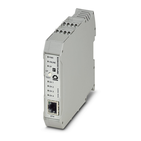
The appearance of the 8 Fuse module is illustrated in Figure 1.
Figure 1 –Appearance of 8 Fuse module

ENG
1.1.2 Specifications
The main specifications and performance characteristics of the 8 Fuse module are given in
Table 1.
Table 1 –The main specifications and performance characteristics
Parameter
Value
Rated voltage, V
-48
Supply voltage range, V
from -36 to -60
Power line fuse capacity*, А
2
Quantity of power lines connected
8
Electrical safety class under GOST IEC 61140-2012
III
Air pressure range, kPa
from 84 to 106,7
Type of climatic design, type of atmosphere according to GOST 15150
NF4.1
Category of seismic resistance according to NP-031-01
I
Safety class according to NP-001-15* and NP-033-11
3N
Air ambient temperature range, ºC
from -5 to +55
Minimum clamped cable section, mm2
0,2
Maximum clamped cable section, mm2
2,5
Overall dimensions, no less than, mm
125×65×66
Weight, no less than, kg
0,25
* It is allowed to use fuses of the power supply line with a nominal value of up to 3 A.
** Compliance of the product with safety class 4N according to NP-001-15 is allowed.

ENG
1.1.3 Scope of supply
The scope of supply of the 8 Fuse module is given in Table 2.
Table 2 –Scope of supply
Identification
Name
Quantity,
pcs.
Note
ARMT.665200.104
8 Fuse module
1
Operational documentation
ARMT.665200.104PP
Product Passport
1
ARMT.665200.104UM
User Manual
1
8 Fuse module is a printed board with clamping elements for DIN-rail 35/7,5, mounted
at racks or cabinets in accordance with DIN 41494 (see Figure 2). Eight fuses are located at
the board to provide protection from short-circuit of 8 power lines and both central and
subscriber exchanges, intercom and control panel equipment, four terminal blocks Х1…Х4,
and eight LEDs for indication of the blown fuse (see Figure 2):

ENG
1 –contacts for 1-16 Х1 terminal block for power lines of subscriber equipment; 2 –VD1-VD8 –
LEDs (RED) for indication of the blown fuses F1 –F8. Solid lighting for identification of the blown fuse;
3 –F1- F8 –Holders with fuses; 4 –Х2 Terminal block, its contact are closed with K1 relay contacts in
case of fuse malfunction. It can be used for alarm signaling using an external executive device
(a lamp, a siren, etc.). The switching voltage is up to 250VAC, the switching current is up to 7А;
5 –Х3 Terminal block, duplicates the contacts of X2 terminal block to connect several 8 fuse modules
in parallel, to connect to the common signal even if one/several fuse(s) is/are blown;
6 –Х4 terminal block to connect the power supply source

Figure 1 –External appearance and overall dimensions of 8 Fuse module
The power voltage for the communication systems DCN, IPN is connected to X4
terminal block «POWER INPUT», the power lines of the subscriber equipment are connected
to the contacts of X1 terminal block. To set up the single failure alarm system, the signaling
cables from X2 terminal blocks for the backup 8 modules applied in the communication
system are connected to X3 terminal block.
8 Fuse module can perform the following functions within the digital intercom DCN
and IPN communication systems manufactured by Armtel:
Transmission of the input power voltage of 48V DC from X4 terminal block
«POWER INPUT» to the power lines connected to Х1.1-Х1.4 terminal blocks;

ENG
LED failure indication (illumination of the corresponding diode) upon the
breakdown of one or several fuse(s);
generate a failure alarm «Alarm» to Х2 terminal block as closing of the relay
contact, if one or several fuse(s) is (are) blown. It can be applied for alarm
signaling using external executive device (a lamp, a siren etc.);
generate a failure alarm «Alarm» to X3 terminal block of the main module in
one or several back-up 8 module(s) connected to X3 terminal block of the main
module.

ENG
1.1.4 Marking
A bilingual nameplate made by laser engraving is pasted on the bottom of the 8 Fuse
module case.
The nameplate contains the following information:
name, trademark, and reference information of the manufacturer;
product name and designation;
permissible operating temperature range;
degree of protection provided by enclosures (IP code);
commercialization mark for products on the market of Customs Union member
states;
mark III electrical safety class according to GOST IEC 61140-2012;
special waste disposal mark;
product serial number;
date of manufacture.
The serial number is unique for each product.

ENG
1.1.5 Package
The 8 Fuse module with the assembly kit and documents, which come with the supply
package, is packed in a consumer package (cardboard box) according to GOST 23088-80.
A label in Russian language and English language is glued onto the consumer package,
said label containing the following inscriptions and symbols:
product name and description;
name, trademark, and reference information of the manufacturer;
handling symbols according to GOST 14192-96 and CU TR 005/2011;
commercialization mark for products on the market of Customs Union member
states;
serial number and date of manufacture.
The package is made according to the drawings of the product manufacturer and
enables storage of the 8 Fuse module, provided requirements set in Section 5 are met. For
shipment of the 8 Fuse module from the manufacturer, consumer package contents are
placed in the package place, which ensures protection from mechanical damage, direct
ingress of atmospheric precipitation, dust, and solar radiation during transportation

ENG
2 INTENDED USE
2.1 Operating limits
2.1.1 8 Fuse module shall be used under exposure factors and ambient
parameters which do not exceed permissible values given in Table 1.
2.1.2 The requirements for operating conditions and the choice of the place of
installation given in this document take into account the most typical factors that
affect the operation of the 8 Fuse module.
Factors that cannot be predicted, estimated, or verified, and which the manufacturer
was unable to factor in during development may exist or arise during operation at the
operating facility.
In the event of such factors, find another operating site where said factors do not exist
or do not affect the operation of the product.
2.2 Preparation for use
Preparation of 8 Fuse module for use is carried out by representatives of the
manufacturer, or by personnel who have been trained (instructed) in the operation of
products of Armtel LLC. The main preparation of the product for use is carried out during
installation and connection. Preparation of 8 Fuse module for work includes several activities:
1. Removing 8 Fuse module and connection cables from the shipping container.
2. Removing 8 Fuse module and connection cables from the customer package.
3. Check the scope of supply of 8 Fuse module according to the product passport.
4. Conduct an external inspection of the product for the absence of damage (cracks,
dents, etc).
5. Install the 8 Fuse module at the place of operation (snap on the DIN rail). The place
in the cabinet should be chosen taking into account the convenience of access to
the module for connecting wires, as well as for maintenance.
6. Connect the common power cable to the terminal block X4, and the power cables
of the actuators to the terminal block X1. In the case of using an additional 8 Fuse
module, connect the same-name contacts of the terminal block X2 of the
additional module and the contacts of the terminal block X3 of the main 8 Fuse
module with wires of the required length with a cross-section of at least 0.2 mm2.
7. In the passport, make notes about the place and time of installation of the module
8 fuses.

ENG
2.3 Safety measures when using the product for its intended purpose
It is strictly forbidden to remove and install fuses in the product connected to the
power supply network.
It is forbidden to operate the product in rooms with high humidity (above 80%)
or the presence of conductive dust.
It is forbidden to operate a damaged product.
2.4 Operation
2.4.1 General information
8 Fuse module can be used as assigned to provide power supply for the subscriber
equipment of all types with input operation voltage of -48V. The input and output cables
should be connected with regard to the contact marking (see Figure 1).
2.4.2 Troubleshooting
Possible problems and their solutions are given in Table 3.
Table 3 –Troubleshooting
Problem
Possible cause
Solutions
Power supply of one or several
subscriber equipment is missing.
One or several LEDs is (are)
illuminated.
The fuse (fuses) is/ are
blown.
Find the failure and clear the
short circuit. Replace the faulty
fuse (fuses).
If the fuse is blown at the backup
module, «Alarm» signal is not
shaped at the main module.
Х2 terminal block of the
backup module is not
connected to Х3 terminal
block of the main
module.
Check reliability of analogous
contacts connection of the
terminal blocks at both the
main and backup modules.

ENG
3 MAINTENANCE
3.1 General guidelines
Maintenance shall be carried out to ensure the module’s fault-free performance and
instant readiness for use.
The objects of maintenance are:
8 Fuse module;
cables suitable for the product.
Maintenance and servicing should be performed once a year without switching off
the product.
3.2 Safety precautions
The product provides safety for service personnel and meets the safety requirements
set out in GOST IEC 61140-2012 and GOST IEC 60127-6-2013.
During maintenance, observe safety precautions according to general and local
“Occupation safety rules when operating electrical installation”.
3.3 Maintenance procedure
The maintenance and servicing of the product include the following activities:
visual inspection of 8 Fuse module for damages (cracks, dents, etc.) and fractures
of suitable wires or cables are not allowed (the bend radius must be at least five
cable diameters);
visual inspection of supply wires and cables (they should not be squeezed or
have damage of the outer shell);
if required, the terminal blocks and board should be completely cleaned up from
dust using air jet purging. Prevent ingress of contaminants and fines removable
during air jet purging into the cabinet, rack or other equipment modules
installed.
check that the wires and cables are properly connected to the terminal blocks.
Verify that the wires and cables are not tensioned;
check the status of the signaling elements.
The approximate time for maintenance and servicing is 30 min.

ENG
3.4 Checking the functionality of the product
The supply voltage for the subscriber equipment can be checked in its normal
operation.

ENG
4 REPAIR
No scheduled repair work is provided for the 8 Fuse module.
Unscheduled repair shall be performed by the manufacturer at the request of the User.
The place, time, procedure, and cost of the work shall be agreed upon with the manufacturer
in advance.
5 STORAGE
Conditions for storage of the 8 Fuse module are in the manufacturer’s individual
package according to the group 1 GOST 15150-69 in heated and ventilated warehouses or
air-conditioned storage facilities with a temperature range from + 5 °C to + 40 °C.
There should not be any aggressive impurities in the air of the product storage room
(vapors of acids, alkalis).

ENG
6 TRANSPORTATION
The product shall be transported in in the manufacturer's individual package as a
packaging unit by road, river, railway, and air transport (expect unsealed compartments),
with compliance with the following conditions:
absence of direct ingress of atmospheric precipitation, water splashes, solar UV
radiation, dust, sand, aerosols;
the shipping container on the shipping vehicle is fastened to avoid falling and
collision.
Note –It is allowed to transport the 8 Fuse module as part of a communication cabinet
(rack) in which other equipment intended for installation in the cabinet is installed. The 8
Fuse module must be mounted on a DIN rail.
7 DISPOSAL
The product is not to be disposed of together with household waste and should be
delivered to a specialized center for the disposal of electronic products. The operating
organization must take full responsibility for the product disposal.

armtel.com
info@armtel.com © Armtel

ARMTEL LLC
Tel./fax: +7 (812) 703-41-11
www.armtel.com | [email protected]
Legal and physical address: 12 buildung 1, Zaporozhskaya street,
office 1/2, Saint Petersburg, 192012
TECHNICAL SUPPORT
8-800-500-90-17 (for calls from Russian Federation)
+7-812-633-04-02 (for international calls)
MORE INFORMATION ABOUT PRODUCT ON OFFICIAL SITE
2018
Table of contents
Other ARMTEL Control Unit manuals
Popular Control Unit manuals by other brands

K+R Performance Engineering
K+R Performance Engineering PRO-CUBE Installation and operating manual

National Instruments
National Instruments PXI Terminal Block NI TB-2708 installation guide

KSB
KSB STAAL 40 AKDS operating manual

EsiWelma
EsiWelma Sensigas UCE18 installation instructions

Johnson Controls
Johnson Controls TrueRH Series Care, use and installation instructions

ASEPCO
ASEPCO PN05 Installation, operating and maintenance manual