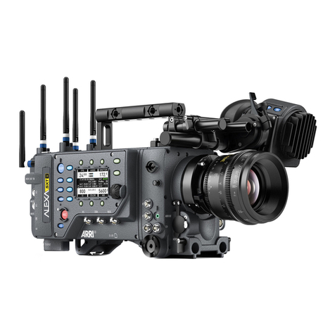
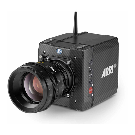
ARRI ALEXA Mini LF User manual

ALEXA Mini LF
Software Update Package 7.3
U S E R M A N U A L
October 9, 2023

Disclaimer 2
1 Disclaimer
Before using the products, be sure to read and understood all respective instructions.
The products are available for commercial customers only.
For product specification changes since this manual was published, refer to the latest publications of
ARRI data sheets or data books, etc., for the most up-to-date specifications. Not all products and/or
types are available in every country. Please check with an ARRI sales representative for availability and
additional information.
ARRI assumes no responsibility for any errors that may appear in this document. The information is
subject to change without notice.
While ARRI endeavors to enhance the quality, reliability and safety of their products, customers agree
and acknowledge that the possibility of defects thereof cannot be eliminated entirely. To minimize
risk of damage to property or injury (including death) to persons arising from defects in the products,
customers must incorporate sufficient safety measures in their work with the system and have to heed
the stated canonic use.
ARRI or its subsidiaries expressly exclude any liability, warranty, demand or other obligation for any
claim, representation, or cause, or action, or whatsoever, express or implied, whether in contract or tort,
including negligence, or incorporated in terms and conditions, whether by statue, law or otherwise. In
no event shall ARRI or its subsidiaries be liable for or have a remedy for recovery of any special, direct,
indirect, incidental, or consequential damages, including, but not limited to lost profits, lost savings, lost
revenues or economic loss of any kind or for any claim by third party, downtime, good will, damage to or
replacement of equipment or property, any cost or recovering of any material or goods associated with
the assembly or use of our products, or any other damages or injury of the persons and so on or under
any other legal theory.
Neither ARRI nor its subsidiaries assume any liability for infringement of patents, copyrights or other
intellectual property rights of third parties by or arising from the use of ARRI products or any other
liability arising from the use of such products. No license, express, implied or otherwise, is granted
under any patents, copyrights or other intellectual property right of ARRI or others.
ARRI or its subsidiaries do not assume any responsibility for incurred losses due to improper handling
or configuration of the camera or other system components, due to sensor contamination, occurrence
of dead or defective pixels, defective signal connections or incompatibilities with third party recording
devices.
In the case one or all of the foregoing clauses are not allowed by applicable law, the fullest extent
permissible clauses by applicable law are validated.

Imprint 3
Imprint
© 2023 Arnold & Richter Cine Technik GmbH & Co. Betriebs KG. All rights reserved.
The system contains proprietary information of Arnold & Richter Cine Technik GmbH & Co. Betriebs
KG; it is provided under a license agreement containing restrictions on use and disclosure and
protected by copyright law. Reverse engineering of the software is prohibited.
No part of this publication may be reproduced, stored in a retrieval system, or transmitted in any form
or by any means, electronic, mechanical, photocopying, recording or otherwise without the prior written
permission of Arnold & Richter Cine Technik GmbH & Co. Betriebs KG.
Due to continued product development the information in this document may change without notice.
The information and intellectual property contained herein is confidential between ARRI and the client
and remains the exclusive property of ARRI. If you find any problems in the documentation, please
report them to us in writing. ARRI does not warrant that this document is flawless.
ARRI, ALEXA Mini LF and ARRIRAW are trademarks or registered trademarks of Arnold & Richter Cine
Technik GmbH & Co. Betriebs KG. All other brands or products mentioned are trademarks or registered
trademarks of their respective holders and should be treated as such.
Apple ProRes 422 HQ, Apple ProRes 4444, Apple ProRes 4444 XQ, and the
ProRes logo are trademarks or registered trademarks of Apple Computer, Inc., used
under license therefrom.
Original version.
For Further Assistance
Arnold & Richter Cine Technik GmbH & Co. Betriebs KG
Herbert-Beyer-Strasse 10
D-80807 Munich
Germany
E-mail: [email protected]
www.arri.com/en/technical-service

Contents 4
2 Contents
1 Disclaimer.......................................................................................................................... 2
2 Contents.............................................................................................................................4
3 About this Document....................................................................................................... 7
4 About this Product........................................................................................................... 8
4.1 Intended Use.................................................................................................................... 8
4.2 Product Identification........................................................................................................ 8
4.3 Technical Data.................................................................................................................. 9
4.4 Scope of Delivery and Warranty.................................................................................... 11
4.5 Declarations of Conformity............................................................................................. 11
5 Safety Instructions..........................................................................................................16
5.1 Safety Conventions and Product Labels........................................................................16
5.2 General Safety Instructions............................................................................................ 17
6 Camera Body Overview................................................................................................. 21
6.1 Camera Rear Connectors...............................................................................................23
6.2 Camera Left and Front Connectors............................................................................... 25
6.3 Media Bay....................................................................................................................... 26
7 Multi Viewfinder MVF-2 Overview................................................................................. 27
8 Camera Control Monitor CCM-1 Overview...................................................................31
9 Camera Support.............................................................................................................. 33
10 Power Supply.................................................................................................................. 36
11 Lens Mounts....................................................................................................................38
11.1 Changing the Lens Mount.............................................................................................. 40
12 Menu Operation...............................................................................................................42
12.1 HOME Screen.................................................................................................................42
12.2 Working with Settings/Lists and Importing Files.............................................................45
12.3 On-screen Keyboard.......................................................................................................47
12.4 Function Button FN.........................................................................................................47
12.5 Overlay Menu................................................................................................................. 48
12.6 User Storage...................................................................................................................49
12.7 Info Screens....................................................................................................................50
13 Status Information and Overlays.................................................................................. 52
14 Main Parameters............................................................................................................. 56
14.1 Project Settings...............................................................................................................56
14.2 Sensor Frame Rate........................................................................................................ 58

Contents 5
14.3 Shutter.............................................................................................................................58
14.4 Exposure Index...............................................................................................................59
14.5 ND Filter..........................................................................................................................60
14.6 White Balance.................................................................................................................60
14.7 Timecode.........................................................................................................................60
15 Look Settings.................................................................................................................. 64
15.1 Processing and Color Spaces........................................................................................66
15.2 Noise Reduction............................................................................................................. 67
16 Recording.........................................................................................................................69
16.1 Recording Medium..........................................................................................................69
16.2 Recording Codec............................................................................................................ 72
16.3 Recording Resolution..................................................................................................... 73
16.4 Starting Recording.......................................................................................................... 77
16.5 File Naming Scheme...................................................................................................... 77
16.6 Audio Recording............................................................................................................. 78
16.7 Rec Beeper and Tally..................................................................................................... 80
17 Playback...........................................................................................................................81
18 Monitoring........................................................................................................................83
18.1 Surround View................................................................................................................ 83
18.2 Magnification................................................................................................................... 84
18.3 Frame Lines.................................................................................................................... 85
18.4 Exposure Tools............................................................................................................... 87
18.4.1 False Color................................................................................................................... 87
18.4.2 Zebra.............................................................................................................................89
18.5 Peaking........................................................................................................................... 90
18.6 Zoom............................................................................................................................... 91
18.7 SDI Settings.................................................................................................................... 92
18.8 Preventing Damage to SDI Outputs...............................................................................93
18.9 EVF and Flip-out Monitor Settings................................................................................. 95
18.10 SDI Color Bars................................................................................................................96
19 User Buttons................................................................................................................... 97
20 Synchronization............................................................................................................ 101
20.1 EXT Sync...................................................................................................................... 102
21 Sensor Settings.............................................................................................................106
21.1 Mirroring the Sensor Image..........................................................................................106
21.2 User Pixel Masking.......................................................................................................106
22 System Settings............................................................................................................ 108
22.1 Language Setting..........................................................................................................108

Contents 6
22.2 System Time and Date.................................................................................................108
22.3 Button and Display Settings......................................................................................... 108
22.4 Fan Settings..................................................................................................................108
22.5 Battery Warning............................................................................................................ 109
22.6 Reset of Electronic Horizon..........................................................................................109
22.7 Update...........................................................................................................................110
22.7.1 Update of Camera Software.......................................................................................110
22.7.2 Update of Camera Components................................................................................ 110
22.7.3 Update of LBUS Devices........................................................................................... 111
23 User Setups................................................................................................................... 112
23.1 User Setup Parameter Blocks......................................................................................113
24 Network.......................................................................................................................... 114
24.1 WiFi Settings.................................................................................................................114
24.2 Ethernet Settings.......................................................................................................... 116
25 Metadata.........................................................................................................................117
26 Lens & Electronic Control System (ECS).................................................................. 119
26.1 Changing a Lens.......................................................................................................... 119
26.2 Lens Data..................................................................................................................... 120
26.3 Lens Data Archive........................................................................................................ 121
26.4 White Radio Configuration............................................................................................122
26.5 Lens Motors.................................................................................................................. 125
26.6 EF Lens Iris Adjustment............................................................................................... 126
26.7 Enable Lens Mount.......................................................................................................126
27 Remote Control............................................................................................................. 127
27.1 Web Remote................................................................................................................. 127
27.2 Camera Access Protocol (CAP)................................................................................... 128
27.3 Camera Companion App.............................................................................................. 129
27.4 Hand Units Hi-5 and WCU-4........................................................................................129
28 Transvideo Starlite HD5-ARRI Monitor.......................................................................130
29 Appendix........................................................................................................................ 132
29.1 Sensor Related Information / 有关影像传感器的信息...................................................132
29.2 Companion Tools.......................................................................................................... 134
29.3 Connector Pin-Outs...................................................................................................... 136
29.4 Cleaning Instructions.................................................................................................... 138
29.5 Repair............................................................................................................................139
29.6 Disposal.........................................................................................................................139
29.7 ARRI Service Contacts.................................................................................................139

About this Document 7
3 About this Document
This user manual is aimed at everyone involved in using the system and provides directions on how to
operate it safely and as intended.
To ensure safe and correct use, all users need to read the ALEXA Mini LF User Manual before using
the system for the first time. It contains detailed information on how to use the system safely.
This user manual is an essential part of the product and should be easily accessible and in proximity to
the equipment so that users can use it as a reference anytime.
Keep the user manual and all other instructions belonging to the system in a safe place for future
reference and possible subsequent owners.
Document Revision History
Document ID: D45 10004716
Version
6.0
6.0.15
6.0.22
7.0
7.1
7.2
7.3
Release
K10155
K10213
K10436
K10627
K10738
K11156
K11332
Date
July 15, 2019
September 10, 2019
September 17, 2020
April 20, 2021
August 4, 2021
February 15, 2023
October 9, 2023
How To Use This Manual
All directions are given from a camera operator's point of view. For example, camera right side refers to
the right side of the camera when standing behind the camera and operating it in a normal fashion.
Connectors are written in all capital letters, for example “AUDIO connector”.
Buttons are written in italic typeface capital letters, for example “PLAY button”.
Menu paths are written in italic typeface, with menu and home in capital letters, for example “MENU >
Recording > Sensor Mode”.
“EVF” refers to the OLED eyepiece of the MVF-2 viewfinder.
“Monitor” refers to the flip-out monitor of the MVF-2 viewfinder.
“VF” refers to the viewfinder connector VF. When settings refer to VF, they affect the EVF and the flip-
out monitor.
“Monitoring outputs” refers to EVF, flip-out monitor, SDI 1 and SDI 2.
“Status Info” refers collectively to the Status Info of EVF, SDI 1 and SDI 2.
Strengthen Your Knowledge and Get Trained
The ARRI Academy courses provide unrivaled insights into the full possibilities of working with ARRI
camera systems, lenses, lights and accessories.
To learn more, please visit http://arri.com/academy.

About this Product 8
4 About this Product
4.1 Intended Use
ATTENTION
All versions of the product are intended exclusively for professional use and may only be used
by skilled personnel. Every user should read and understand the operating instructions and the
user manual. Use the product only for the purpose described in this document. Always follow the
instructions and system requirements for all equipment involved.
The ALEXA Mini LF is a large format digital camera solely and exclusively for recording images at
various resolutions suitable for a variety of distribution formats:
Open Gate 4.6K, 16:9 4.6K, 4K, UHD, 2K and HD recording resolutions
ARRIRAW and Apple ProRes codecs
LogC4 or ARRIRAW encoding
Codex Compact Drive recording
Up to 120 fps
Only use the ALEXA Mini LF as described in the operation manual and user manual. Any other use
is considered improper and can result in personal injury and/or property damage. ARRI assumes no
liability for damages or changes that are caused by improper use.
The entire product may not be changed or converted.
4.2 Product Identification
1
2
The camera serial number (1) and the FCC/CE confor-
mity label (2) are located on the bottom of the camera.
The serial number consists of the last 5 digits of the
product number K1.0024074-XXXXX.

About this Product 9
4.3 Technical Data
Sensor Type Large Format ARRI ALEV III (A2X) CMOS sensor with Bayer pattern color filter array
Sensor Photosites and Size 4448 x 3096
36.70 x 25.54 mm / 1.444 x 1.005“
Ø 44.71 mm / 1.760“
Sensor Frame Rates 0.75 - 100 fps
Project Frame Rates 23.976, 24, 25, 29.97, 30, 47.952, 48, 50, 59.94, 60 fps
Weight ~ 2.7 kg / ~ 5.7 lbs (camera body with LPL lens mount)
Photosite Pitch 8.25 μm
Recording Resolutions Active Image Area
(Dimensions)
Active Image Area
(Photosites)
Recording Resolution
(Pixel)
Max. fps
4.5K (4448 x 3096) 40 fps (ARRIRAW)
4.5K LF 3:2 Open Gate 36.70 x 25.54 mm
1.445 x 1.006“ 4448 x 3096
4.5K (4480 x 3096) 40 fps (ProRes)
4.5K (4448 x 1856) 60 fps (ARRIRAW)
4.5K LF 2.39:1 36.70 x 15.31 mm
1.445 x 0.603“ 4448 x 1856
4.5K (4480 x 1856) 60 fps (ProRes)
UHD (3840 x 2160) 40 fps (ProRes)
4.3K LF 16:9 35.64 x 20.05 mm
1.403 x 0.789“ 4320 x 2430
HD (1920 x 1080) 75 fps (ProRes)
UHD (3840 x 2160) 60 fps (ARRIRAW)
60 fps (ProRes)
2K (2048 x 1152) 90 fps (ProRes)
3.8K LF 16:9 31.68 x 17.82 mm
1.247 x 0.702“ 3840 x 2160
HD (1920 x 1080) 90 fps (ProRes)
2.8K (2880 x 2880) 60 fps (ARRIRAW)
2.8K LF 1:1 23.76 x 23.76 mm
0.935 x 0.935“ 2880 x 2880
2.8K (3072 x 3024) 60 fps (ProRes)
3.4K S35 3:2 28.25 x 18.16 mm
1.112 x 0.714“ 3424 x 2202 3.4K (3424 x 2202) 60 fps (ARRIRAW)
3.2K S35 16:9 26.40 x 14.85 mm
1.039 x 0.585“ 3200 x 1800 3.2K (3200 x 1800) 75 fps (ProRes)
2.8K S35 4:3 23.76 x 17.81 mm
0.935 x 0.701“ 2880 x 2160 2.8K (2880 x 2160) 75 fps (ProRes)
2.8K S35 16:9 23.76 x 13.36 mm
0.935 x 0.526“ 2880 x 1620 HD (1920 x 1080) 100 fps (ProRes)
Exposure Index Adjustable from EI 160-3200 in 1/3 stops, EI 800 base sensitivity
Dynamic Range 14+ stops over the entire sensitivity range from EI 160 to EI 3200 as measured with the ARRI Dynamic
Range Test Chart (DRTC-1)
Shutter Electronic shutter, 5.0°- 356° or 1s - 1/8000s
Recording Codecs MXF/ARRIRAW
MXF/Apple ProRes 4444 XQ
MXF/Apple ProRes 4444
MXF/Apple ProRes 422 HQ
Recording Media Codex Compact Drive 1TB (CA08-1024), Codex Compact Drive 2TB (CB16-2048)
Recording Modes Standard real-time recording
Viewfinder Type Multi Viewfinder MVF-2 with OLED viewfinder display (1920 x 1080) and
4“ LCD flip-out touchscreen monitor (800 x 480)
Viewfinder Diopter Adjustable from -5 to +5 diopters
Color Output Rec 709, Rec 2020, LogC3

About this Product 10
Look Control Custom color look (through ARRI Look File ALF4 or ARRI Look Library)
White Balance Manual and auto white balance, adjustable from 2000K to 11000K
Color correction adjustable from -16 to +16 CC
(1 CC corresponds to 035 Kodak CC values or 1/8 Rosco values)
Filters Four position built-in motorized ND filter: Clear, 0.6, 1.2, 1.8
Fixed optical low pass, UV, IR filter
Lens Squeeze Factors 1.00, 1.25, 1.30, 1.50, 1.65, 1.80, 2.00
Exposure and Focus Tools False Color, Zebra, Zoom, Aperture and Color Peaking
Audio Recording 4 channel linear PCM (24 bit, 48 kHz)
Image Outputs 1x VF custom CoaXPress connectors for MVF-2 viewfinder / Camera Control Monitor CCM-1
2x SDI outputs on BNC connectors, both outputs carry uncompressed video with embedded audio and
metadata.
SDI 1: HD only, Processed or Clean, with or without a look file ap- plied 1.5G 422 HD (SMPTE ST292-1, up
to 30 fps, p or psf) 3G 422 HD (SMPTE ST425-1, up to 60 fps, p) 3G 444 HD (SMPTE ST425-3, up to 30
fps, p)
SDI 2: HD or UHD, Clean only, with or without a look file applied, or SDI 1 clone 1.5G 422 HD (SMPTE
ST292-1, up to 30 fps, p or psf) 3G 422 HD (SMPTE ST425-1, up to 60 fps, p) 3G 444 HD (SMPTE
ST425-3, up to 30 fps, p) 6G 422 UHD (SMPTE ST2081-10, up to 30 fps, p)
“Clean” is an image without surround view or overlays (status, false col- or, zebra, framelines, etc.),
“Processed” is an image supporting surround view and overlays.
Interfaces 1x TC (LEMO 5-pin) for timecode In/Out
1x ETH (LEMO 10-pin) for remote control and service
1x SYNC IN (BNC) for Genlock synchronization
1x EXT (LEMO 7-pin), multi purpose accessory interface w. RS pin and 24V power output
1x LBUS (LEMO 4-pin) for lens motors, daisy chainable (on lens mount)
1x USB 2.0 for user setups, look files etc
Audio Inputs 1x AUDIO (LEMO 6-pin) for balanced stereo line in
(line input max. level +24 dBu correlating to 0 dBFS)
Two built-in microphones for scratch audio
Audio Outputs 1x 3.5 mm stereo headphone connector (on MVF-2)
2x SDI (embedded audio)
Power Inputs 1x BAT (LEMO 8-pin)
11.0 - 34.0 V DC
Power Outputs 1x RS (Fischer 3-pin) for 24 V accessory power out, start/stop and shutter pulse
1x 12 V (LEMO 2-pin) for 12 V accessory power out
1x LBUS (LEMO 4-pin) for lens motors & 24 V power out (on lens mount)
1x AUDIO (LEMO 6-pin) for balanced stereo line in and 12 V accessory power out
1x ETH (LEMO 10-pin) for remote control, service and 24 V accessory power out
Remote Control Options Camera Companion App
ARRI Electronic Control System (ECS)
Web-based remote control from phones, tablets and laptops via WiFi & Ethernet
Camera Access Protocol (CAP) via WiFi & Ethernet
GPIO interface for integration with custom control interfaces
Wireless Interfaces Built-in WiFi module (IEEE 802.11b/g)
Built-in White Radio for ARRI ECS lens and camera remote control
Lens Mounts & Adapters ARRI LPL Mount (LBUS)
ARRI PL-to-LPL Adapter
ARRI EF Mount (LBUS)
Leitz M Mount for ARRI
Flange Focal Depth LPL Mount: 44 mm
PL-to-LPL Adapter: 52 mm
Power Consumption ~ 69 W when recording ARRIRAW LF 16:9 UHD at 24 fps with MVF-2 attached
Measurements (HxWxL) 140 x 143 x 188 mm / 5.5 x 5.6 x 7.4“ (camera body with LPL lens mount)

About this Product 11
Operating Temperature -20° C to +45° C / -4° F to +113° F @ 0-95% RH
Storage Temperature -30° C to +70° C / -22° F to +158° F
Sound Level < 20 dB(A) at 24 fps
4.4 Scope of Delivery and Warranty
ATTENTION
The packaging consists of recyclable materials. For the sake of the environment, dispose the
packaging material at a suitable disposal site.
Always store, ship and dispose according to local regulations. ARRI is not liable for consequences
from inadequate storage, shipment or disposal.
For scope of warranty, please ask your local ARRI service partner. ARRI is not liable for
consequences from inadequate shipment, improper use or use of third-party products.
On delivery, please check if package and content are intact. Never accept a damaged/incomplete
delivery.
K1.0024074 ALEXA Mini LF Camera Body
A complete delivery includes:
ALEXA Mini LF camera body
Lens mount cover
White Radio Antenna
WiFi Antenna
3.0 mm Allen key
USB memory stick incl. user manual
4.5 Declarations of Conformity
Approval Information
The products offered by ARRI are approved for use in a number of countries. Product-specific
information on approval can be found in the respective operating instruction manuals. Import and use
in countries other than those mentioned in the respective operating instructions may be subject to
legal, regulatory, or official requirements and regulations. Before the products are imported into these
countries or used in these countries, compliance with the existing legal, regulatory, and administrative
requirements and regulations must be ensured. It is the importer's or the user's responsibility, prior
to importation or use, to inform themselves of the applicable legal, regulatory, and administrative
requirements and regulations and to ensure compliance with these requirements and regulations,
including applying for and obtaining any necessary approvals or registrations.
As far as reasonable and legally possible, ARRI will support requests in relation to such applications by
providing technical documents or declarations. As an importer or user, you confirm that you are familiar
with and comply with the legal, regulatory, and administrative requirements and regulations that apply
in the countries to which you ship or use the products. You further confirm that you will arrange for any
necessary registrations, enrollments, or authorizations that are required in such countries.
You release ARRI from all obligations resulting from any legislative, regulatory, or administrative
requirements regarding import or use of the products, except in countries where ARRI has obtained
a registration or certification. You agree to indemnify, defend, and hold ARRI harmless from any and

About this Product 12
all claims, damages, losses, liabilities, costs, and expenses (including reasonable fees of attorneys
and other professionals) that may arise out of a demand on ARRI in connection with your obligations
mentioned above.
EU Declaration of Conformity
Brand Name: ARRI
Product Description: Digital Camera System
ARRI ALEXA MINI LF + Multi Viewfinder MVF-2
+ Europe Setting for Software 6.0 or later, Primes following Appendix I, Antenna following Appendix
II
The designated products conform to the specifications of the following European directives:
1 Directive 2014/53/EU of the European Parliament and the Council of 16 April 2014 on the
harmonization of the laws of the Member States relating to the making available on the market
of radio equipment - OJ L 153, 22 May 2014, p. 62–106.
2 Directive 2011/65/EU of the European Parliament and the Council of 8 June 2011 on the
restriction of the use of certain hazardous substances in electrical and electronic equipment -
OJ L 174, 1 July 2011, p. 88–110.
The compliance with the requirements of the European Directives was proved by the application of
the following standards:
Essential Requirements regarding No 1:
Following Art. 3.1 a,
2014/35/EU:
EN 62368-1:2014 + AC:2015-05 + AC:2015-11;
EN 62311:2008
Following Art. 3.1 b,
2014/30/EU:
EN 301 489-1 V2.1.1
EN 301 489-17 V3.1.1
EN 55032:2015
EN 55035:2017
Art. 3.2 EN 300 328 V2.1.1
Essential Requirements regarding No 2:
EN 50581:2012
To evaluate the respective information, we used:
http://ec.europa.eu/growth/single-market/european-standards/harmonised-standards/index_en.htm
Year of affixed CE-marking: 2019
APPENDIX I - List of Primes
Item Model Name
1 ARRI Signature Primes with Lens Data System 2 with focal length 18-280 mm
2 PL-to-LPL Adapter + ARRI Lenses with Lens Data System 1
APPENDIX II - List of Antennas
Item Manufacturer Model Name Gain
(dBi)
Radiation
Pattern
Type Connector
For ECS White Radio RF Module EMIP400s:
1 Nearson S131AM-2450S 2.0 Omni-directional Dipole Reverse SMA

About this Product 13
Item Manufacturer Model Name Gain
(dBi)
Radiation
Pattern
Type Connector
2 Proant 333 (Ex-it 2400
Foldable)
2.0 Omni-directional Dipole Reverse SMA
3 Radial/Larsen R380.500.125 2.0 Omni-directional Dipole Reverse SMA
4 Wanshih WSS002 2.0 Omni-directional Dipole Reverse SMA
5 Taoglas GW26.0151 1.8 Omni-directional Monopole Reverse SMA
For WiFi 2.4 GHz RF Module ST60-2230C:
6 Radial R380.500.150 0.0 Omni-directional Monopole Reverse SMA
7 LAIRD LSR/001-009 2.0 Omni-directional Dipole Reverse SMA
FCC Compliance Statement
Class B Statement: This equipment has been tested and found to comply with the limits for a Class B
digital device, pursuant to part 15 of the FCC Rules. These limits are designed to provide reasonable
protection against harmful interference in a residential installation. This equipment generates, uses and
can radiate radio frequency energy and, if not installed and used in accordance with the instructions,
may cause harmful interference to radio communications. However, there is no guarantee that
interference will not occur in a particular installation. If this equipment does cause harmful interference
to radio or television reception, which can be determined by turning the equipment off and on, the user
is encouraged to try to correct the interference by one or more of the following measures:
Reorient or relocate the receiving antenna.
Increase the separation between the equipment and receiver.
Connect the equipment into an outlet on a circuit different from that to which the receiver is
connected.
Consult the dealer or an experienced radio/TV technician for help.
WIFI: FCC ID: SQG-60SIPT
ECS transceiver module: FCC ID: Y7N-EMIP400
Industry Canada Compliance Statement
Complies with the Canadian ICES-003 Class B specifications.
Cet appareil numérique de la Classe B est conforme à la norme NMB-003 du Canada.
This device contains licence-exempt transmitter(s)/receiver(s) that comply with Innovation, Science and
Economic Development Canada’s licence-exempt RSS(s). Operation is subject to the following two
conditions:This device may not cause interference. This device must accept any interference, including
interference that may cause undesired operation of the device.
L’émetteur/récepteur exempt de licence contenu dans le présent appareil est conforme aux CNR
d’Innovation, Sciences et Développement économique Canada applicables aux appareils radio
exempts de licence. L’exploitation est autorisée aux deux conditions suivantes :L’appareil ne doit pas
produire de brouillage;L’appareil doit accepter tout brouillage radioélectrique subi, même si le brouillage
est susceptible d’en compromettre le fonctionnement.
WIFI: IC ID: 3147A-602230C
ECS transceiver module: IC ID: 9482A-EMIP400

About this Product 14
China
ALEXA Mini LF:本设备型号核准代码为
CMIIT ID: 2020AP8258
Singapore
Dealer's License No: DA103787
Registration valid until 31. August 2024 for ALEXA Mini LF
(EMIP400s & LAIRD ST60-2230C)
India WPC Compliance Statement
Registration No.: ETA-SD-20201108443
Japan Australia & New Zealand
ECS Transceiver Module
EMIP400: 020-180030
WiFi Module: 003-170091
ALEXA Mini LF
Cambodia Philippines
Type Approval
TRC Indentifier 0256-2019-
niLF
No. ESD – 1921399C
Egypt South Africa
TAC.24121919782.WIR TA 2019/2202 APPROVED
South Korea
ALEXA Mini LF: Certification No: R-R-ARg-ALEXA_Mini_LF
ECS Transceiver Module: Certification No: R-CRM-ARg-EMIP400
WiFi Module: Certification No: MSIP-CRM-LAI-60-2230C

About this Product 15
United Arab Emirates
Wireless video devices: Dealer No: DA68290/17
(Registration valid until: 28th August, 2022; brand registration: 5 years)
ALEXA Mini LF: registered No: ER74494/19
Thailand
Supplier Declaration of Conformity - 55/107 No 2932
Peru
Certificado de Homologación
INFORME # 2858-2019-MTC/29.01.LIM.H
Codigo: TRSS44872.
Emisión 23/10/19.
Taiwan
WiFi module: NCC: CCAF20LP1330T0
ECS transceiver module: NCC: CCAH18LP0660T0
取得審驗證明之低功率射頻器材,非經核准,公司、商號或使用者均不得擅自變更頻率、加大功
率或變更原設計之特性及功能。低功率射頻器材之使用不得影響飛航安全及干擾合法通信;經發
現有干擾現象時,應立即停用,並改善至無干擾時方得繼續使用。前述合法通信,指依電信管理
法規定作業之無線電通信。 低功率射頻器材須忍受合法通信或工業、科學及醫療用電波輻射性電
機設備之干擾。

Safety Instructions 16
5 Safety Instructions
This safety information is in addition to the product specific operating instructions in general and must
be strictly observed for safety reasons. Read and understand all safety and operating instructions
before you operate or install the system. Retain all safety and operating instructions for future
reference. Always follow the instructions in this and all documents supplied with the device to avoid
injury to yourself or others and damage to the system or other objects.
Assembly and operation should only be carried out by trained staff familiar with the system. Only
use the tools, materials and procedures recommended in this document. For the correct use of other
equipment, see the manufacturer's instructions.
5.1 Safety Conventions and Product Labels
Structure of Safety and Warning Messages
These instructions use safety instructions, warning symbols and signal words to draw your attention to
different levels of risk:
WARNING
WARNING indicates a potentially hazardous situation which, if not avoided, may result in death or
serious injury.
Always follow the recommended measures to avoid this hazardous situation.
CAUTION
CAUTION indicates a potentially hazardous situation which, if not avoided, may result in minor or
moderate injury.
Always follow the recommended measures to avoid this hazardous situation.
ADVICE
ADVICE signifies a potentially hazardous situation which can result in damage to property.
Always follow the recommended measures to avoid this hazardous situation.
ATTENTION
Not relevant to safety, ATTENTION provides additional information to clarify or simplify a procedure.
Warning Symbols and Product Labels
General warning sign Warning of electrical voltage
Warning of hot surfaces Warning of hand injuries
Warning of the risk of crushing Warning of obstacles on the ground

Safety Instructions 17
Please read all instructions care-
fully before using the product for
the first time.
Direct Current symbol found on elec-
tronics requiring or producing DC
power
5.2 General Safety Instructions
WARNING
Operation of the Camera System in Case of Obvious Damage
Risk of electric shock and fire hazard caused by short circuit.
Do not use the system if electrical lines or housing are visibly damaged.
Operate the system using only the type of power source indicated in the manual.
Unplug the power cable by gripping the power plug, not the cable.
Do not operate the system in areas with humidity above operating levels or expose it to water or
moisture.
Do not get the system wet.
Do not lay cables over sharp edges (e.g. sheet metal, profile or other cut edges). Damaged
cables can cause electric shock, short circuit or fire.
Do not remove or deactivate any safety measures from the system (incl. warning stickers or paint
marked screws).
Repairs may only be carried out by authorized ARRI service partners.
WARNING
Falling System Parts
If the system is inadequately built up or assembled, it can fall down and cause serious in-
juries and damage to the system or property.
Installation and operation may only be carried out by trained personnel who are familiar with the
system. Observe accident prevention regulations.
Do not place the camera system on an unstable trolley or hand truck, stand, tripod, bracket, table
or any other unstable support device.
Always place the camera on dedicated support devices.
Secure the camera system and its accessories against falling and tipping over. Observe the
general and local safety regulations.
When using the camera system on camera cranes, a suitable safety rope must be used.
WARNING
Positioning the Camera System on an Inclined or Unsafe Plane
Risk of injury caused by the camera system tipping over.
Observe the accident prevention regulations.
Put the camera system on level and stable ground
Do not place the system on an unstable trolley or hand truck, stand, tripod, bracket, table or any
other unstable support device.
Always place the camera on dedicated support devices.
Use only accessories approved by ARRI. The use of accessories not approved by ARRI is at
your own risk. Please observe all relevant safety guidelines

Safety Instructions 18
WARNING
Overloading the Camera System by Persons or Objects
Risk of injury caused by the camera system tipping over.
Do not lean on the camera system.
Do not place any unauthorized objects on the camera system.
Do not hang any unauthorized objects on the camera system.
Use only accessories approved by ARRI. The use of accessories not approved by ARRI is at
your own risk. Please observe all relevant safety guidelines
WARNING
Changing the Lens Mount while the Camera is Powered
Risk of electric shock and permanent damage to the camera and lens mount.
Always switch off the camera and disconnect all power supplies before changing the lens mount.
CAUTION
Using the Camera or Camera Accessories in a Humid Environment and with Con-
densation
When moving the camera and the camera accessories from a cool to a warm location or
when the camera is used in a damp environment, condensation may form inside the cam-
era, on the sensor, and on internal or external electrical connections. Operating the cam-
era while condensation is present bears risk of electric shock and/or fire caused by a short
circuit.
Never operate the camera and camera accessories when condensation occurs.
After moving the camera and camera accessories from a cool to a warm environment, wait for
some time for the system to warm up.
To reduce the risk of condensation, find a warmer storage location.
CAUTION
Hot Surfaces on Camera Body and Camera Accessories
During extended operation, high data rates and/or operation at high ambient temperatures,
the camera's surface and the area around the fan outlet can get hot. Direct sunlight can re-
sult in camera housing temperatures above 60° C (140° F).
Never cover, obstruct or block the fan in- or outlets while the camera is powered.
Do not place the camera system near any heat sources during operation.
At ambient temperatures above 25° C (77° F), protect the camera and camera accessories from
direct sunlight.

Safety Instructions 19
CAUTION
Hot Surfaces on Recording Media
During extended operation, high data rates and/or operation at high ambient temperatures,
the recording media in the camera can get hot to the touch and can cause pain or even
burns if held for too long directly after removal.
Do not handle the recording media for longer than three seconds and remove it quickly but
carefully.
Consider to wear protective gloves when removing the recording media or allow it to cool down
beforehand.
Do not put any labels or adhesive tape on the recording media (especially the side facing the
camera body). The recording media must have full contact to the thermal surface to ensure
proper heat conduction.
CAUTION
Rotating Lens Motor
Risk of crushing fingers and capturing and unraveling long hair, jewelry and/or clothing.
Make sure that the lens motor is properly attached to the lens.
Do not touch the lens motor gears while they are moving.
Keep hair and loose clothing away from the motor gear teeth.
Keep cables connected to the camera away from the motor gear teeth.
CAUTION
Connected Cable on the Floor
Risk of injury caused by tripping, falling or slipping over connected cables.
Always properly secure cables connected to the camera and camera accessories.
Install cables in a way that they cannot be tripped over.
If necessary, use a cable duct or secure the cables with adhesive tape.
Disconnect the cables from the camera and camera accessories before moving.
CAUTION
Unhealthy Posture or Excessive Physical Exertion During Camera Operation
Using the camera in shoulder mode, on portable stabilizer systems, etc., as well carrying
for transport in general bears risk of permanent long term physical damage.
Ensure an ergonomic posture when operating and carrying the camera.
ADVICE
High Energy Light Sources
Permanent damage to the camera sensor and/or the viewfinder display.
Do not point the camera sensor into direct sunlight, very bright light sources or high energy light
sources (e.g. laser beams).
Do not point the viewfinder eyepiece into direct sunlight, very bright light sources or high energy
light sources (e.g. laser beams).

Safety Instructions 20
ADVICE
Open Lens Mount
When no lens or lens cap is attached to the camera, dirt and dust particles may enter the
camera and settle on the sensor cover glass. Particles on the sensor cover glass can later
be visible in the recordings made by the camera.
Place the protective cap on the lens mount, when no lens is attached to the camera
Contact ARRI Service to inspect the camera if undefined spots appear in the image.
ADVICE
Connection of Onboard Monitor
Damage to the SDI driver chip caused by power surge.
Always make sure to plug in the power cable first and then connect the BNC cable. As soon as
the power and BNC cables are connected, you can switch the camera or the accessories on or
off.
Always make sure to disconnect the BNC cable first and then disconnect the power cable.
Only use shielded power cables to power accessories that connect to the camera with a BNC
cable. When only the plus pin connects on a shielded power cable, the shield will act as the
power return and therefore not damage the SDI output.
Other manuals for ALEXA Mini LF
2
Table of contents
Other ARRI Digital Camera manuals

ARRI
ARRI Hi-5 SUP 2.1 How to use

ARRI
ARRI Arricam Lite User manual

ARRI
ARRI Amira User manual

ARRI
ARRI AMIRA SUP 6.1.2 How to use

ARRI
ARRI ALEXA Mini User manual

ARRI
ARRI Arricam System User manual

ARRI
ARRI ALEXA SXT W User manual

ARRI
ARRI ARRIFLEX 16 St User manual

ARRI
ARRI Amira User manual

ARRI
ARRI ALEXA Mini LF How to use

ARRI
ARRI ALEXA User manual

ARRI
ARRI ARRIFLEX 16 BL User manual

ARRI
ARRI 535 User manual

ARRI
ARRI ALEXA User manual

ARRI
ARRI ALEXA 35 SUP 1.0.3 How to use

ARRI
ARRI ALEXA User manual

ARRI
ARRI ARRIFLEX 435 XTreme User manual

ARRI
ARRI ARRIFLEX 435 XTreme User manual

ARRI
ARRI ALEXA Mini LF SUP 7.1 Beta User manual

ARRI
ARRI 535B Operator's manual