ARRI Amira User manual

AMIRA
Q U I C K G U I D E
Date: 02 April 2014
AMIRA
Q U I C K G U I D E
Date: 02 April 2014

2 Imprint
Imprint
Copyright
© 2014 Arnold & Richter Cine Technik GmbH & Co. Betriebs KG. All rights reserved.
No portions of this document may be reproduced without prior written consent of
Arnold & Richter Cine Technik GmbH & Co. Betriebs KG. Specifications are subject to
change without notice. Errors, omissions, and modifications excepted.
AMIRA, ALEXA, and ALEXA XT are trademarks or registered trademarks of Arnold
& Richter Cine Technik GmbH & Co. Betriebs KG. All other brands or products are
trademarks or registered trademarks of their respective holders and should be treated
as such.
Original version.
NOTICE
This document is a Quick Guide only. For detailed operation instructions, please
refer to the User Manual.
For further assistance
Arnold & Richter Cine Technik GmbH & Co. Betriebs KG
Tuerkenstr. 89
D-80799 Munich, Germany
E-mail: [email protected]
www.arri.com/service
Document revision history
Version
1.0
ID
K4.0001898
Release
K08511
Date
02 April 2014

Contents 3
Contents
1 For your safety.................................................................................................5
1.1 Risk levels and alert symbols............................................................... 5
1.2 Vital precautions.................................................................................... 5
1.3 General precautions.............................................................................. 6
2 Audience and intended use............................................................................7
3 Scope of delivery and warranty..................................................................... 8
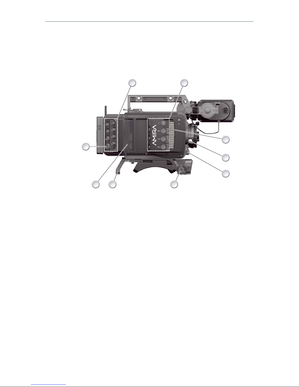
4 Camera layout.................................................................................................. 9
4.1 Product identification........................................................................... 13
5 Power supply..................................................................................................14
5.1 Changing a Gold Mount battery.......................................................... 14
5.2 Changing a V-Lock battery..................................................................15
5.3 BAT in..................................................................................................15
5.4 Powering auxiliary devices via camera............................................... 15
6 Switching on/off............................................................................................. 16
7 Connectors..................................................................................................... 17
7.1 Front connectors..................................................................................17
7.2 Audio connector panel.........................................................................18
7.3 I/O panel.............................................................................................. 20
7.4 Media panel......................................................................................... 22
7.4.1 Preparing a USB memory stick......................................................22
7.4.2 Changing a CFast 2.0 card............................................................23
8 Lens mount/filters..........................................................................................25
8.1 ND filter switch.................................................................................... 25
8.2 Changing a lens.................................................................................. 26
9 Audio control panel.......................................................................................27
9.1 Channel configuration..........................................................................27
9.2 Headphone volume............................................................................. 29
10 Main controls and viewfinder.......................................................................30
10.1 PK peaking button...............................................................................30
10.2 EXP exposure tool button................................................................... 31
10.3 VF1 & VF2 user buttons..................................................................... 31
10.4 Recording.............................................................................................32
10.5 PLAY button........................................................................................ 33
10.6 Diopter adjustment.............................................................................. 33
10.7 Adjusting the monitor...........................................................................34

4 Contents
10.8 Changing the monitor mode................................................................34
10.9 Menu access....................................................................................... 35
11 User preset panel.......................................................................................... 37
11.1 Locking/unlocking................................................................................ 37
11.2 User buttons........................................................................................ 37
12 Operator panel............................................................................................... 39
12.1 Setting the US switch function............................................................ 39
12.2 Presetting the US / EI / WB switches..................................................40
12.3 AW auto white balance button............................................................ 41
13 Camera preparation.......................................................................................42
13.1 Adjusting the viewfinder...................................................................... 42
13.2 Balancing the camera weight.............................................................. 43
13.3 Mounting to a wedge plate..................................................................44
13.4 Mounting to a bridge plate.................................................................. 45
14 Assembly and retrofits..................................................................................46
14.1 Battery adapter.................................................................................... 46
14.2 Base adapter....................................................................................... 48
14.3 Camera handle.................................................................................... 50
14.4 Viewfinder and EVF cable...................................................................51
14.5 Antennas..............................................................................................54
15 Licensing and updating................................................................................ 55
15.1 Camera updates.................................................................................. 55
15.2 Licensing..............................................................................................55
16 Appendix......................................................................................................... 56
16.1 Dimensions and weight (with PL mount).............................................56
16.2 Electrical data...................................................................................... 56
16.3 Declarations of conformity...................................................................56

For your safety 5
1 For your safety
Before use, please ensure that all users comprehensively read, understand, and
follow the instructions in this document.
1.1 Risk levels and alert symbols
Safety warnings, safety alert symbols, and signal words in these instructions indicate
different risk levels:
DANGER!
DANGER indicates an imminent, hazardous situation which, if not avoided, will
result in death or serious injury.
WARNING!
WARNING indicates a potentially hazardous situation which, if not avoided, may
result in death or serious injury.
CAUTION!
CAUTION indicates a potentially hazardous situation which, if not avoided, may
result in minor or moderate injury.
NOTICE
NOTICE explains practices not related to physical injury. No safety alert symbol
appears with this signal word.
Note: Provides additional information to clarify or simplify a procedure.
1.2 Vital precautions
DANGER!
High voltage! Risk of electric shock or fire!
Short-circuits will entail lethal damage.
Before use, read and follow all valid instructions.
Use solely and exclusively as described in the instructions.
Never open. Never insert objects.
For operation, always use a power source as indicated in the instructions.
Always unplug the power cable by gripping the power plug, not the cable.
Never try to repair. All repair work should be done by a qualified ARRI Service
Center.
Never remove or deactivate any safety equipment (incl. warning stickers or paint-
marked screws).
Always protect from moisture, cold, heat, dirt, vibration, shock, or aggressive
substances.
Never cover any fan openings.

6 For your safety
CAUTION!
Condensation! Risk of electric shock and fire!
Condensation may form on the sensor and electrical connections when exposing
the camera to sudden changes of temperature or humidity.
To avoid injury and damage, never operate the camera when condensation occurs
CAUTION!
Heavy weight! Risk of injury and damage!
If placed on an unstable position, the camera can fall and cause serious harm.
Always place the camera on proper support devices. Safely attach it as described in
the instructions.
1.3 General precautions
NOTICE
Even rugged cameras use components sensitive to improper use.
Always unplug the camera from power sources before making changes to setup or
system (in particular: changing cables).
Protect the optical system and sensor: Never point the camera or viewfinder into
direct sunlight.
Avoid permanent sensor damage: Never let any direct light or reflections from high-
energy light sources (e.g. laser beams) enter the camera's optical path.
Protect the sensor: Always keep a lens or protective cap on the empty lens mount.
Change lenses in dry, dust-free environments only.
Clean the sensor cover glass solely and exclusively as described in the User
Manual. If this fails, consult an ARRI Service Center. Never try to remove the glass.
Only use the tools, materials and procedures recommended in this document. For
the correct use of other equipment, see the manufacturer's instructions.

Audience and intended use 7
2 Audience and intended use
NOTICE
The product is solely and exclusively available for commercial costumers and shall
be used by skilled personnel only. Every user should be trained according to ARRI
guidelines.
Use the product only for the purpose described in this document. Always follow the
valid instructions and system requirements for all equipment involved.
The AMIRA is a 35 mm digital camera solely and exclusively for recording HD 1080 or
2K images suitable for a variety of distribution formats:
•ProRes 422, ProRes 422 LT, ProRes 422 HQ* and ProRes 4444* codecs
•REC 709 encoding (through use of look files) or Log C* encoding
•CFast 2.0 card recording
•Up to 200 fps* with full image quality
•35 mm CMOS sensor
•EVF with OLED eyepiece
•Fold-away monitor for both live view and user interface access
•Ready out-of-the-bag for single-user-centric workflow
•Lean and rugged construction for high mobility
* Feature requires licensing.

8 Scope of delivery and warranty
3 Scope of delivery and warranty
NOTICE
Product and packaging contain recyclable materials. Always store, ship, and
dispose of according to local regulations.
ARRI is not liable for consequences from inadequate storage, shipment or disposal.
Delivery
On delivery, please check if package and content are intact. Never accept a damaged/
incomplete delivery. A complete delivery includes:
•AMIRA camera with lens mount according to order: PL, EF, B4
•Multi-viewfinder with AMIRA EVF cable
•Gold Mount or V-Lock battery adapter, if ordered
•Camera handle with viewfinder adapter
•Four XLR connector caps (one spare; keep all four for later use!)
•Four BNC connector caps (remove before use)
•WPA-1 or BPA-3 base adapter, if ordered
•WiFi antenna
•Bluetooth antenna
•USB memory stick
•2 mm Allen key
•3 mm Allen key
•Quick Guide
•Original packaging incl. drying agent
Usually, the camera comes fully assembled. In the unlikely case that a handle,
viewfinder, adapter, or antenna (etc.) is not assembled, see Page 46 for
instructions.
NOTICE
ARRI offers an increasing variety of product bundles and additional accessories.
For details, please consult our website or your local ARRI Service Partner.
Warranty
For scope of warranty, please ask your local ARRI Service Partner. ARRI is not liable
for consequences from inadequate shipment, improper use, or third-party products.

Camera layout 9
4 Camera layout
Right
3
2
1
9
8
7
6
5
4
1BAT power input 6RS connector
2I/O panel 7Bracket rosette
3Audio connector panel 8WPA-1 with quick release connectors
4Fan intake 9Fan outlet
512-pin Hirose for ENG type lenses

10 Camera layout
Left
1
2
3 4
5 6
7
89
10
1Operator panel 6Media panel (behind lid)
2User buttons 7Battery adapter
3Power button & camera lock 8Fan intake
4Audio control panel 9Recording button
5Lid 10 Bracket rosette

Camera layout 11
Top
1
8
2
3
4
5
6
7
1Viewfinder top buttons 5Adjustable beam
2Recording button 6Camera type label
3Viewfinder hinge with clamp 7Level
4Accessory shoe 8Accessory threads on camera handle
Bottom
1
2
5
3
4
1Battery adapter 4Viewfinder type label
2Bracket rosettes 5WPA-1 quick-lock bracket
3PLAY button

12 Camera layout
Front
1
2
3
4
5
1Clamps 415 mm rod receptacles
2Lens mount (here: PL) 5RS connector
3ND filter switch
Back
1
2
3
4
5
6
7
8
1Fold-away monitor (viewfinder/GUI) 5I/O panel
2OLED eyepiece 6BAT power input
3Bluetooth antenna 7Battery adapter (here: Gold Mount)
4WiFi antenna 8Proximity sensor for OLED eyepiece

Camera layout 13
4.1 Product identification
1
2
CE type labels with serial number are on the camera top (1) and under the viewfinder
(2). An FCC conformity label is on the camera bottom.

14 Power supply
5 Power supply
Depending on your battery demand, the camera offers either a Gold Mount or a V-
Lock adapter. You can change both by yourself (see Page 46). For further details,
see our website or ask your local ARRI Service Partner.
NOTICE
For maximum operation time, always use fully charged batteries with 10.5 to 34 V
DC (50 W minimum).
5.1 Changing a Gold Mount battery
1
2
3
1. Place the battery pins in the mount receptors (1).
2. Slide the battery (2) to the right until the adapter audibly locks (1).
3. To release: With the lever pushed (3), slide the battery (2) to the left and
backwards.

Power supply 15
5.2 Changing a V-Lock battery
1
2
3
1. Place the battery's wedge into the V-shaped lock (1).
2. Slide the battery (2) downwards until the adapter audibly locks (1).
3. To release: With the pin pushed (3), slide the battery (2) up- and backwards.
5.3 BAT in
NOTICE
If the power supply to BAT is interrupted with the camera switched on, the camera
will automatically repower and boot-up on reconnection.
Use the BAT connector, and a KC50-S or KC50-SP-S cable, to
supply the camera with 10.5 to 34 V DC.
5.4 Powering auxiliary devices via camera
You can supply auxiliary devices from the camera via several connectors (2.0 A max):
•12 V via 2-pin LEMO, 4-pin Hirose, or via D-tap on battery adapter
•24 V via RS
•Camera voltage via EXT
Note: For connector pin-out information, see the User Manual. With a critical power
supply level, the camera switches off all auxiliary power supplies first.

16 Switching on/off
6 Switching on/off
1
2
3
1. To switch on: Press the power button (1).
2. The ARRI logo appears in audio display (2) and monitor (3).
3. To switch off: Press and hold the power button (1).
4. A countdown appears in audio display, monitor, and viewfinder.
5. On reaching zero, the camera powers off.
1
6. Note: The STBY icon (1) signals that the camera is ready to record.
7. If not: Insert a CFast 2.0 card. See Page 42.
8. Format the card for recording.

Connectors 17
7 Connectors
NOTICE
Connecting or disconnecting devices or cables while recording can disturb the
audio/image signal due to static electricity.
7.1 Front connectors
1
2
112-pin Hirose for ENG type
lenses
23-pin Fischer RS
ENG (12-pin Hirose)
Supplies lens servos with power and provides access to lens ser-
vo functions.
RS (3-pin Fischer)
This 3-pin Fischer socket for RS input supplies external acces-
sories with 24 V power (2.0 A). It also carries a frame pulse out-
put and accepts an ARRI remote start/stop trigger.

18 Connectors
7.2 Audio connector panel
NOTICE
Rubber caps protect the XLR connectors from dirt and moisture. Always cap
unused XLR connectors.
2
3
4
5
6
1
1Protective caps
2Headphone out & volume
3XLR 5-pin audio input
4-5 XLR 3-pin audio input
6Preset options
Headphone
Headphone 3.5mm stereo TRS (“Mini-jack”) output for monitoring
audio channels.
IN A (5-pin XLR)
XLR input for microphone signals (including 48V phantom power
supply) and line level signals.
IN B & C (3-pin XLR)
XLR input for microphone signals (including 48V phantom power
supply), line level signals and AES3 digital.

Connectors 19
Connecting audio devices
2
3
4
5
6
1
1. Uncap the needed connectors only (1).
2. Connect the headphone (2).
3. Set the headphone volume by turning the wheel (2).
4. Alternatively, you can use the SET wheel on the camera's left. See Page 29.
5. Via switch (3 to 5), select the appropriate setting for your audio device (6):
°48V: Microphone level signals with phantom power supply
°MIC: Analog microphone level signals
°LINE: Analog line level signals
°AES3: AES/EBU signals
6. Connect each device (3 to 5) until the connector audibly locks.
Disconnecting audio devices
1
1
1
1. Press the PUSH button to unlock (1).
2. Remove the cable by pulling on the connector.
3. Replace with another cable.
4. Or: Cap the connector for protection.

20 Connectors
7.3 I/O panel
NOTICE
If the power supply to BAT is interrupted with the camera switched on, the camera
will automatically repower and boot-up on reconnection.
4
3
2
1
5
6
7
1BAT main power in
2EXT in/out
3D-tap
4Aux power out
5HD-SDI image out 1 & 2
6Return/sync in
7Timecode in/out
12V (4-pin Hirose)
Supplies 12 V auxiliary power with a maximum power of 2.0 A.
12V (2-pin LEMO)
Supplies 12 V auxiliary power with a maximum power of 2.0 A.
D-tap
A D-tap on the battery adapter supplies accessories with 12 V
DC from the camera.
Other manuals for Amira
4
Table of contents
Other ARRI Digital Camera manuals

ARRI
ARRI ARRIFLEX 16 BL User manual

ARRI
ARRI 535 User manual

ARRI
ARRI ALEXA Mini LF User manual

ARRI
ARRI Arricam Lite User manual

ARRI
ARRI ALEXA Mini User manual

ARRI
ARRI ARRIFLEX 435 XTreme User manual

ARRI
ARRI ALEXA SXT W User manual

ARRI
ARRI ARRIFLEX 435 XTreme User manual

ARRI
ARRI ALEXA User manual

ARRI
ARRI 535B Operator's manual

ARRI
ARRI ALEXA User manual

ARRI
ARRI ALEXA 35 SUP 1.0.3 How to use

ARRI
ARRI ALEXA 35 User manual

ARRI
ARRI ALEXA 35 User manual

ARRI
ARRI ARRIFLEX 16 St User manual

ARRI
ARRI AMIRA SUP 4.0 How to use

ARRI
ARRI ALEXA User manual

ARRI
ARRI ALEXA Mini How to use

ARRI
ARRI ALEXA User manual

ARRI
ARRI ALEXA Mini LF SUP 7.1 Beta User manual