ARRI SkyPanel S360-C Manual

S360-C
Arnold & Richter Cine Technik GmbH & Co. Betriebs KG, Pulvermühle, D-83071 Stephanskirchen, Germany | www.arri.com
L5.0016312
Short Instruction
Kurzanleitung
Mode d’ Emploi
࣮ࣘࢨ࣮࣐ࢽࣗࣝ
11 / 2017

2
1
3
5
4
6
8
9
10 11 12
13
14 15 16
1 Spigot Aufhängezapfen
2 Stirrup Haltebügel
3 Tilt lock Bügelklemmung
4 Handle Griff
5 Eyelet Halteöse
6 Diffuser / Intensifier Diffusor / Intensifier
7 Antenna for wireless DMX Antenne (drahtloses DMX)
8 USB A port USB-AAnschluss
9 DMX input DMX Eingang
10 DMX through DMX Ausgang
11 Ethernet connector RJ45 Netzwerkanschluss RJ45
12 DC 54 V = Input Spannungseingang 54 V=
13 Fixture menu Gerätemenü
14 DC 54 V= Output Spannungsausgang 54 V=
15 Power in Netzspannungseingang
16 Power switch Netzschalter
A Locking Pin Verriegelungsstifte
B Guiding Pin Führungsstifte
C Safety loop attachment Ankerpunkt für Sicherungsseil
3
4
4
4
5
5
5
B
A
7
C
5

3
Intended use
This product is intended to illuminate persons and objects in a
dry environment.
Always follow the safety information.
Any usage other than described above is not permitted and can
damage the product and lead to associated risks such as short-
circuit, fire, electric shock, etc. You are not allowed to modify the
product.
This product fulfills legal requirements.
General Notes
• The SkyPanel soft lights are intended for professional use
and may only be operated by qualified persons.
• Please read these instructions carefully before using the
product for the first time. The following text contains import-
ant information for safe handling.
• For your personal safety, please observe the safety
instructions and warnings.
• Observe all common and local safety regulations.
• Please keep these instructions for possible subsequent
owners.
• Please dispose the packing material at your local recycling
center for environmental protection.
• Defective products shall be disposed appropriately. For fur-
ther information please ask your ARRI dealer or your local
authorities.
• Use only original ARRI spare parts and accessories.
Safety Instruction
DANGER OF LIFE – MAINS VOLTAGE!
• Do not open the housing of the SkyPaneland the power
supply. For safe operation, the housing must be completely
closed at all times.
• Always earth the fixture electrically. Only use TN- or TT one
phase power supplies and a power plug according to IEC
60309-1 or a similar national standard.
• Use only genuine ARRI Power supply units (PSU) and
connector cables designed for the SkyPanel. The use of
third-party power supply units and connector cables void
the warranty.
• Do not use any cable to hold, move or suspend the fixture
or the power supply unit.
• Check the mains cable and connector cables prior to every
operation for damage.
• You must not connect or disconnect the connector cable
when the power supply unit is powered.
• In case of visible damage to cables or housings, the device
may not be operated any longer. Damaged components of
the housing must be replaced by an ARRI service center.
CAUTION – HIGH BEAM INTENSITY!
Do not look into the active light source of the
SkyPanel.
Always observe the minimum distance to persons and
flammable objects given on the type plate.
Warnings
• Do not cover the ventilation slots of the fixture or the power
supply unit. Unobstructed airflow is required for effective
cooling.
• Avoid direct illumination by other fixtures or other heat
sources.
To Secure the Fixture and its Accessories
• Whenmountedinahanging position or above persons, use
a suitable safety cable to prevent the SkyPanel and the
attached accessories against falling when the primary
mounting method fails.
• Thesafetycableand its connecting elements must be rated
at a minimum load of 10 times the weight of the device and
all attached accessories.
• Lead the safety cable
• around the carbon fiber yoke and through the safety loop
attachment (C), or
• around the short yoke and through one of the safety loop
attachments (C)
and the structure the fixture is mounted to.
• The safety cable must be kept short.
• Both locking pins (A) must snap in the guide holes of the
diffuser / intensifier firmly.
• Theaccessoriesmustbe insertedcorrectly intheaccessory
guiding rails of the diffuser / intensifier.
• Attach an appropriate rated safety cable to the safety hole
in the accessory. Affix the safety cable to the rigging struc-
tureorthesafetyloopattachment (C) of the SkyPanel yoke.
• Donotstore the remote controlinthetroughwhen using the
fixture over head.
• The four eyelets (5) can be used to hang the fixture horizon-
tally. Attach an appropriately rated safety cable to each eye-
let. Four safety cables are required in total. Secure the
opposite end of each safety cable with one appropriately
rated shackle to form a single hoist point.
• Tripods must be set up in a stable way and must be rated to
carry the required load. Please observe the weight of the
accessories and the cables. Please refer also to the leaflet
„Operating your ARRI Lampheads Safely“ L5.40731.E.
Basic Functions
MOUNTING
The SkyPanel must be mounted on its yoke (2) in a standing
position or a hanging position. Always insert the 28 mm spigot
(1) into the bushing of a suitable stand or a suitable clamping
system and fix and secure the spigot afterwards.
PAN AND TILT
• Swivel the SkyPanel after loosening the screw of the stand
orthe clamping system. The tilt angle can be adjusted by re-
leasing both tilt locks (3). After the adjustment of the pan an-
gle and the tilt angle, the screws respectively clamps must
be fastened again.
TO ADJUST THE BEAM ANGLE
• The beam angle can be adjusted by using different diffuser
panels (6) or the intensifier.
ENGLISH

USE OF LIGHT SHAPING ACCESSORIES
Lightshaping accessorieslike ahoneycombcanbeinsertedinto
the guiding rails of the diffuser at the front of the SkyPanel:
• Open locking pins (A) by pulling them out completely. Tilt
the diffuser forward.
• Slide the accessory from above into the guiding rails of the
diffuser.
• Open both locking pins (A) by pulling them out completely.
Tilt back the diffuser. Both locking pins (A) must snap in the
guide holes of the diffuser firmly.
DMX INTERFACE
The SkyPanel is equipped with two locking, 5-pin XLR connec-
tors (10 and 11) for the DMX / RDM data input and throughput.
USB INTERFACE
The SkyPanel is equipped with an USB A interface (9). The
interfacecan beusedfor uploadingnewfirmwareusinga FAT32
formatted USB 1.0 / 2.0 memory stick. The firmware must be
stored in the root directory of the USB memory stick.
WARNING! Check the setting for the USB port in the menu USB
Mode before connecting the memory stick. Select the option
Normal. Otherwise the USB memory stick will not work.
ETHERNET CONNECTOR
The SkyPanel is equipped with an RJ45 Ethernet connector
(12). The interface can be used for uploading new firmware, set-
ting parameters and service purpose using the ARRI lighting
service manager.
The latest firmware and the ARRI Lighting Service Manager
software tool are located in the download area of our website
www.arri.com for free download.
WDMX INTERFACE
The SkyPanel S360-C is equipped with a LumenRadio Wireless
DMX (CRMX) receiver. It can communicate DMX and RDM. To
activate this feature, go to the DMX Settings menu item and turn
the WDMX Data State to „On“. Link your LumenRadio transmit-
ter to the S360-C by pressing the „Link“ button on your transmit-
ting device.
POWER-ON AND OPERATION
By switching the power switch on (or by applying the mains
power on SkyPanels without a power switch), the SkyPanel
starts lighting after a short startup time with the same setting
which had been active at its last switch off.
The SkyPanel can now be controlled over the DMX interface,
over the USB interface or by the integrated fixture menu (16).
Modes of Operation
WHITE LIGHT
The SkyPanel generates white light with an optimized color
rendition. The color temperature and the green / magenta point
can be continuously adjusted.
COLORED LIGHT
The SkyPanel generates white or colored light. The color tone
(hue) and the color saturation can be adjusted continuously. At
very low color saturation, the SkyPanel generates white light
without an optimized color rendition.
The operating modes can be changed by pressing the MODE
button short.
Indication Panel and Fixture Menu
The SkyPanel is equipped with an integrated fixture menu.
It supports the following functions:
POWER-LED:
DATA-LED:
STATUS-LED:
INTENSITY/SELECTOR ENCODER
• to set the intensity
• turn and press to select a menu or confirm a parameter
CENTRAL ROTARY KNOB
The functionality of the rotary knob is shown in the display. Two
functionalities are available:
• toadjustthecorrelatedcolortemperature(CCT)inthewhite
light mode
• to adjust the color hue in the colored light mode
RIGHT ROTARY KNOB
The functionality of the rotary knob is shown in the display. Two
functionalities are available:
• to adjust the correlated green/magenta correction in the
white light mode
• to adjust the color saturation in the colored light mode
Color Indication
Green Fixture switched on. No error.
No color Fixture switched off.
Color Indication
Blue The fixture receives a valid DMX signal.
Blue /green The fixture receives a valid WDMX signal.
Purple Master mode active
White Receiving valid Art-Net signal, Gateway
active
Green Receiving valid Art-Net signal, Gateway not
active
Orange Receiving valid sACN signal, Gateway active
Cyan Receiving valid sACN signal, Gateway not
active
Red No communication between fixture menu and
controller board.
No light The fixture receives no valid control signal.
Color Indication
Green No error. Normal tempera-
ture.
Red flashing (0,5s rhythm)*
Warning fixture over tem-
perature (only with fan
modes LOW and High
Speed).
Red*Fixture over temperature.
Change from red to green*Fixture normal tempera-
ture.
Red flashing (0,25s
Rhythm)*Calibration data not
loaded.
*Display lights up red when STATUS-LED is lit red
ENGLISH

5
MENU button
Press to open or close the fixtures menu
BACK button
Press to exit a sub-menu without changing a parameter. Opens
the next higher menu level.
MODE Button
Press to change mode between white and colored light.
PRESET Button
• to open the preset-list
• Use the SELECTOR encoder to select a preset
User Manual
The SkyPanel 360-C user manual contains more detailed
information about the features and functionalities of the fixture.
Please visit the website www.arri.com to download the user
manual and much more information about the SkyPanel 360-C
free of charge.
To Replace the Light Source
The light source contained in this luminaire is replaceable by a
serviceagentor a similar qualified person. If the light source has
reached the end of its operational life or if the light source fails
before it reached the end of its specified operational life, please
contact the manufacturer or his service agent or a similar quali-
fied person.
ENGLISH
Design and specifications are subject to change without notice
ARRI Service
In case of technical problems please visit us at
www.arri.com
Arnold & Richter Cine Technik GmbH & Co. KG
Global Application & Services
Pulvermühle
D-83071 Stephanskirchen
Germany

Bestimmungsgemäße Verwendung
Das Produkt dient zur Beleuchtung von Personen und
Gegenständen in trockener Umgebung.
Die Sicherheitshinweise sind unbedingt zu befolgen!
Eine andere als die beschriebene Verwendung führt zur Be-
schädigung dieses Produktes. Dies ist mit Gefahren, wie z.B.
Kurzschluß, Brand, elektrischer Schlag etc., verbunden. Das
Produkt darf nicht geändert bzw. umgebaut werden.
Dieses Produkt erfüllt die gesetzlichen Anforderungen.
Allgemeine Hinweise
• Die SkyPanel Flächenleuchten sind für den professionellen
Einsatz bestimmt. Sie dürfen nur von befähigten Personen
betrieben werden.
• Bitte lesen Sie diese Anleitung sorgfältig vor der ersten
Inbetriebnahme. Der folgende Text enthält wichtige Hin-
weise für die sichere Handhabung.
• Beachten Sie die Sicherheits- und Warnhinweise.
• Beachten Sie alle allgemeinen und örtlichen Sicherheits-
vorschriften.
• Bewahren Sie diese Anleitung für Nachbesitzer auf.
• Entsorgen Sie das Verpackungsmaterial der Umwelt
zuliebe bei einer geeigneten Entsorgungsstelle.
• AuchdefekteGerätemüssensachgerechtentsorgtwerden.
Weitere Informationen hierzu erhalten Sie von Ihrem
ARRI-Händler und Ihrer Gemeinde- oder Stadtverwaltung.
• Verwenden Sie nur Originalersatzteile und Original-
Zubehör von ARRI.
Sicherheitshinweise
VORSICHT NETZSPANNUNG – LEBENSGEFAHR!
• Öffnen Sie das Gerät nicht. Der sichere Betrieb des Schein-
werfers und des Netzteils sind nur bei vollständig geschlos-
senem Gehäuse gewährleistet.
• Der Scheinwerfer muss elektrisch geerdet werden und darf
nur als Einphasen-Betriebsmittel an einem TN- oder
TT-Stromversorgungssystem über einen Stecker nach
IEC 60309-1 oder vergleichbarer nationaler Norm
angeschlossen werden.
• Verwenden Sie nur original ARRI Netzteile und Verbin-
dungsleitungen, die für das SkyPanel entwickelt wurden.
Die Verwendung anderer Netzteile und Verbindungs-
leitungen führt zum Erlöschen der Gewährleistung.
• Verwenden Sie kein Kabel zum Halten, Bewegen oder
Aufhängen des SkyPanels oder des Netzteils.
• Prüfen Sie die Netzleitung und Verbindungsleitungen des
Scheinwerfers vor jedem Gebrauch auf sichtbare Schäden.
• Die Verbindungsleitung darf nur bei ausgeschaltetem
Netzteil verbunden oder getrennt werden.
• Verwenden Sie den Scheinwerfer bei sichtbar beschädig-
ten Leitungen oder Gehäusen nicht. Schäden müssen
durch ein ARRI Service-Center behoben werden.
VORSICHT – HOHE LICHTSTÄRKE!
Nicht in die aktive Lichtquelle des SkyPanels
starren.
Halten Sie die auf dem Typenschild beschriebenen Mindest-
abstände zu Personen und brennbaren Werkstoffen ein.
Warnhinweise
• Decken Sie die Lüftungsöffnungen des Scheinwerfers oder
desNetzteilsniemals ab. DasSkyPanelmussfrei umströmt
werden können, um die Kühlung zu gewährleisten.
• Vermeiden Sie die Bestrahlung durch andere Scheinwerfer
und andere Wärmequellen.
Sicherung des Scheinwerfers und Zubehörs
• Bei hängendem Betrieb und beim Betrieb über Personen
müssen Sie das SkyPanel und das verwendete Zubehör
mittels eines zugelassenen Sicherungsseils gegen Herab-
fallen sichern.
• Das Sicherungsseil und seine Verbindungselemente
müssen mindestens für das 10-fache Gewicht der zu
sichernden Geräte ausgelegt sein.
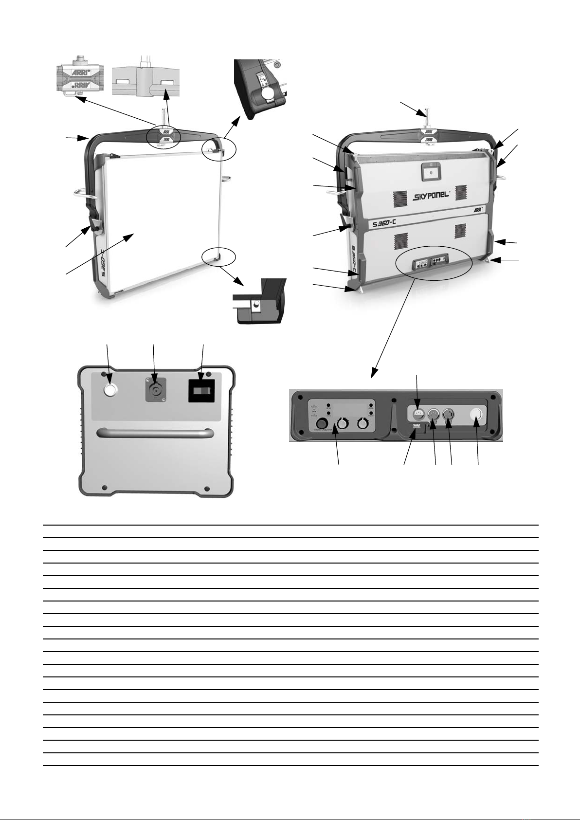
• Führen Sie das Sicherungsseil
• um den Karbon-Bügel und durch die Öse (C) oder,
• um den kurzen Bügel und durch eine der beiden Ausspa-
rungen (C)
und um die tragende Struktur.
• Halten Sie das Sicherungsseil so kurz wie möglich.
• Beide Verriegelungsstifte (A) müssen in die Führungsboh-
rungen des Diffusors / Intensifiers einrasten.
• Das Zubehör muss korrekt in die Führungsschienen des
Diffusors / Intensifiers eingesetzt sein.
• Jedes Zubehör muss mit einem geeigneten Sicherungsseil
gesichertwerden.FührenSiedasSicherungsseildurchden
Ankerpunkt des Zubehörs zur tragenden Struktur oder den
Ankerpunkt (C) am Bügel des SkyPanel.
• Die Fernbedienung darf bei Betrieb über Kopf nicht in der
Mulde am Gerät aufbewahrt werden.
• Die vier Ösen (5) dienen zur horizontalen Aufhängung des
GerätsanviergeeignetenSicherungsseilen.BefestigenSie
je ein Sicherungsseil an jeder Öse. Sie benötigen insge-
samt vier Sicherungsseile. Verbinden Sie die anderen En-
den der Sicherungsseile mit einem geeigneten Schäkel zu
einem Hängepunkt.
• Stative müssen standsicher aufgestellt und für die Last
ausgelegt sein. Beachten Sie hierbei das Gewicht des
Zubehörs und der Kabel. Lesen Sie hierzu auch die
Hinweise im „Sicherheitsmerkblatt für ARRI-Scheinwerfer“
L5.40731.E.
Grundfunktionen
BEFESTIGUNG
Das SkyPanel darf nur an seinem Haltebügel (2) stehend oder
hängend befestigt werden. Schieben Sie den 28 mm Aufhänge-
zapfen (1) in die Hülse eines passenden Stativs oder einer pas-
senden Haltevorrichtung und klemmen Sie ihn fest. Sichern Sie
den Zapfen gegen Herausfallen.
DREHEN UND NEIGEN
Sie können das SkyPanel nach Lösen der Schraube am Stativ
oder der Haltevorrichtung drehen. Verändern Sie die Neigung
nach Lösen der Bügelklemmung (3). Ziehen Sie alle Schrauben
nach dem Einrichten der Flächenleuchte fest an.
EINSTELLEN DES STREUWINKELS
Der Streuwinkel kann durch Verwendung verschiedener
Diffusorplatten (6) oder des Intensifiers geändert werden.
DEUTSCH

7
VERWENDUNG VON ZUBEHÖR FÜR DIE LICHTFORMUNG
Zubehör für die Lichtformung, wie z.B. eine Wabenblende, kann
in die Führungsschienen des Diffusors an der Vorderseite des
SkyPanels eingesetzt werden:
• Ziehen Sie beide Riegel (A) nach oben ziehen und klappen
Sie den Diffusor etwas nach vorne.
• Schieben Sie das Zubehör von oben vollständig in die Füh-
rungsschienen des Diffusors ein.
• ZiehenSiebeide Riegel (A)nachobenund klappen Sieden
Diffusor mit dem montierten Zubehör nach hinten. Lassen
Sie beide Riegel (A) in die Führungsbohrungen des Diffu-
sors einrasten.
DMX-SCHNITTSTELLE
Das SkyPanel verfügt über zwei 5-polige XLR-Verbinder (9 und
10) für den DMX / RDM Datenein- und –ausgang.
USB-SCHNITTSTELLE
Das SkyPanel besitzt eine USB A-Schnittstelle (8) für das Auf-
spielen von Firmware über einen FAT32 formatierten USB 1.0 /
2.0 Memorystick. Die Firmware-Datei muss sich im Stammver-
zeichnis des USB-Memorysticks befinden.
ACHTUNG! Prüfen Sie vor dem Anschluss des USB-Memory-
sticks die Einstellung im Menü USB Mode. Wählen Sie die
Einstellung Normal, da der USB-Memorystick sonst nicht
gelesen werden kann.
NETZWERKANSCHLUSS
DasSkyPanelverfügt über einen RJ45-Netzwerkanschluss(11)
für das Aufspielen von Firmware, die Einstellung von Betriebs-
parametern und Servicezwecke mit Hilfe des ARRI Lighting
Service Managers.
Die neueste Firmware sowie den ARRI Lighting Service
Manager finden Sie im Download-Bereich der ARRI Website
www.arri.com zum kostenlosen Download.
WDMX INTERFACE
DasSkyPanelS360-C ist miteinemLumenRadioWireless DMX
(CRMX)Empfängerausgestattet.Erunterstützt DMX und RDM.
Um das Interface zu aktivieren, öffnen Sie das Menü
DMX SETTINGS und setzen den WDMX Status ON. Verbinden
Sie den LumenRadio Sender mit dem S360-C durch Drücken
der Link-Taste am Sender.
EINSCHALTEN UND BETRIEB
MitdemEinschaltendesNetzschalters(bzw.nachdemAnlegen
der Netzspannung bei Geräten ohne Schalter) beginnt das
SkyPanel nach kurzer Verzögerung mit derjenigen Einstellung
zu leuchten, die bei der letzten Abschaltung aktiv war.
Das SkyPanel kann nun über die DMX-Schnittstelle, über die
USB-Schnittstelle oder über das Gerätemenü (13) gesteuert
werden.
Betriebsarten
WEISSLICHT
Das SkyPanel erzeugt weißes Licht mit optimierter Farbwieder-
gabe. Die Farbtemperatur und die Grün / Magenta-Sättigung
können stufenlos eingestellt werden.
FARBLICHT
Das SkyPanel erzeugt weißes oder farbiges Licht. Der Farbton
(Hue) und die Farbsättigung (Saturation) können stufenlos ein-
gestellt werden. Bei sehr geringer Farbsättigung wird weißes
Licht mit nicht optimierter Farbwiedergabe erzeugt.
Die beiden Betriebsarten können durch kurzes Drücken der Ta-
ste MODE umgeschaltet werden.
Anzeigefeld und Gerätemenü
Das SkyPanel ist mit einem Gerätemenü mit folgenden Funktio-
nen ausgestattet:
POWER-LED:
DATA-LED:
STATUS-LED:
DREHKNOPF INTENSITY/SELECTOR
• Zum Einstellen der Helligkeit.
• Drehen und Drücken zur Auswahl eines Menüs oder eines
Parameters.
MITTLERER DREHKNOPF
DieaktuelleBelegung desDrehknopfswird imDisplayüber dem
Drehknopf gezeigt. Zwei Funktionen stehen zur Auswahl:
• zum Einstellen der korrelierten Farbtemperatur (CCT) im
Weißlicht-Modus.
• zum Einstellen des Farbtons im Farblicht-Modus.
RECHTER DREHKNOPF
DieaktuelleBelegung desDrehknopfswird imDisplayüber dem
Drehknopf gezeigt. Zwei Funktionen stehen zur Auswahl:
• zum Einstellen der Grün/Magenta-Korrektur (CCT) im
Weißlicht-Modus.
• zum Einstellen der Farbsättigung im Farblicht-Modus.
Farbe Bedeutung
Grün Gerät ein. Kein Fehler.
Aus Gerät ausgeschaltet.
Farbe Bedeutung
Blau Das Gerät empfängt ein gültiges DMX Signal.
Blau/grün Das Gerät empfängt ein WDMX Signal.
Violett Das Gerät ist Mastergerät
Weiß Das Gerät empfängt ein gültigesArt-Net
Signal, Gateway aktiv
Grün Das Gerät empfängt ein gültiges Art-Net
Signal, Gateway nicht aktiv
Orange Das Gerät empfängt ein gültiges sACN
Signal, Gateway aktiv
Cyan Das Gerät empfängt ein gültiges sACN
Signal, Gateway nicht aktiv
Rot Keine Kommunikation zwischen Geräte-
menü und Controllerboard.
Aus Das Gerät empfängt kein Steuersignal.
Farbe Bedeutung
Grün Kein Fehler, Temperatur
normal
Blinkt rot (0,5s Rhythmus)*Übertemperatur-Warnung
(nur bei Lüftermodus LOW
und HIGH)
Rot*Übertemperatur erreicht
Wechsel Rot nach Grün*Temperatur normal
Blinkt rot (0,25s Rhythmus)*Kalibrierdaten nicht gela-
den
*Display leuchtet rot, wenn die STATUS-LED rot leuchtet
DEUTSCH

Taste MENU
Drücken, um das Gerätemenü zu öffnen oder zu schließen.
Taste BACK
Drücken, um das aktuelle Menü ohne Änderung eines Parame-
ters zu verlassen. Wechselt in die nächsthöhere Menü-Ebene.
Taste MODE
Drücken, um zwischen Weißlicht und Farblicht zu wechseln.
Taste PRESET
• Öffnet die Liste der verfügbaren Voreinstellungen.
• Auswahl der Voreinstellung mit den SELECTOR Dreh-
knopf.
Bedienungsanleitung
Die Bedienungsanleitung zum SkyPanel 360-C enthält Informa-
tionen zur Verwendung des Geräts. Sie steht zum kostenfreien
Download auf der ARRI Website www.arri.com zur Verfügung.
Hinweis zum Ersetzen des Leuchtmittels
Die Lichtquelle dieser Leuchte darf durch den Hersteller der
Leuchte oder einen von ihm beauftragten Service-Techniker
oder eine vergleichbar qualifizierte Person ersetzt werden.
Wenn die Lichtquelle ihre Lebensdauer erreicht hat oder die
Lichtquelle vor Erreichen der angegebenen durchschnittlichen
Lebensdauer ausfällt, wenden Sie sich bitte an den Hersteller
derLeuchteodereinen von ihm beauftragten Service-Techniker
oder eine vergleichbar qualifizierte Person.
DEUTSCH
Technische Änderungen vorbehalten.
ARRI Service
Bei technischen Problemen besuchen Sie bitte
www.arri.com
Arnold & Richter Cine Technik GmbH & Co. KG
Global Application & Services
Pulvermühle
D-83071 Stephanskirchen
Deutschland

Specification
Technische Daten
SkyPanel S360-C
SkyPanel S360-C Power Supply Unit
Input Voltage
Betriebsspannung Input DC 54 V =
Spannungseingang 54 V =
Max. cable length PSU - luminaire
Max. Leitungslänge Netzteil - Scheinwerfer 32 ft.
10 m
Power Consumption
Leistungsaufnahme 1500 W maximal
Ingress Protection
Schutzart IP20 dry location
IP20 trockene Umgebung
Protection Class
Schutzklasse III
Operating temperature
Zulässige Umgebungstemperatur
ta= -20° C - + 45° C / -4 to +113° F (High Mode / Variable Mode, 1200 W)
ta= -20° C - + 40° C / -4 to +104° F (Normal Mode, 1500 W)
ta= -20° C - + 35° C / -4 to +95° F (Quiet Mode, 1200 W)
Dimensions (WxHxD)
Abmessungen (BxHxT) 62.8 x 48.7 x 8.0 in
1594 x 1237 x 203 mm
Weight
Gewicht 92 lbs (with carbon fiber yoke and diffuser)
42 kg (mit Karbon-Bügel und Diffusor)
Certifications
Zertifizierungen
CE, FCC
Pending: CB, ENEC, cNRTLus, PSE
Note: This equipment has been tested and found to comply with the limits for a Class
A digital device, pursuant to Part 15 of the FCC Rules. These limits are designed to
provide reasonable protection against harmful interference when the equipment is
operated in a commercial environment. This equipment generates, uses, and can
radiate radio frequency energy and, if not installed and used in accordance with the
instruction manual, may cause harmful interference to radio communications. Opera-
tion of this equipment in a residential area is likely to cause harmful interference in
which case the user will be required to correct the interference at his own expense.
Mains input
Netzeingang 100 - 240 V ~, 50/60 Hz
Voltage output
Spannungsausgang DC 54 V =
Dimensions (LxWxH)
Abmessungen (LxBxH) 17.7 x 9.4 x 8.1 in
451 x 240 x 206 mm
Weight
Gewicht 24.7 lbs
11,2 kg
ARRI, ARRIARRI, the ARRI Logo, ARRIMAX, ARRISUN, EB, EBB, L-Series, MAX Technology, M-Series, POCKETPAR, True Blue, SkyPanel,
SKYPANEL, T 12 and T 24 are registered trademarks ofArnold & Richter Cine Technik GmbH & Co. Betriebs KG.

Table of contents
Languages:
Other ARRI Dj Equipment manuals

ARRI
ARRI Claypaky Arolla Aqua User manual

ARRI
ARRI MINI-B AQUA CL3026 User manual

ARRI
ARRI L Series User manual

ARRI
ARRI Claypaky AXCOR BEAM 300 User manual

ARRI
ARRI L10 Manual

ARRI
ARRI L Series User manual

ARRI
ARRI ARRISUN 18 Event User manual

ARRI
ARRI ARRI D 5 Manual

ARRI
ARRI COMPACT 575 Manual

ARRI
ARRI L10 User manual