Arrowhead KP600F/KP600L User manual

KP600F/L
LED/LCD KEYPADS
Owner's Manual
Use with
AV6500 & SP850 Control panels
P/N 64812823 A PDF 10/23/97
IT IS IMPORTANT FOR YOUR SAFETY TO TEST YOUR
SYSTEM AND IT'S COMPONENTS REGULARLY.

2
Table of Contents
Introduction 3
System Configuration 3
Keypad Description 4
Disarming And Silencing Your System 7
Arming Your System 7
Zone Bypass 8
Bypassing a Group of Zones 8
Instant/Delay Mode 9
Arming/Disarming Reports By User 9
Testing the Communicator 9
Testing Your System 10
Smoke Detector Reset 10
Setting Chime Mode 11
Fault Condition 11
Duress (Ambush) 12
Emergency Alarm Key Pairs 13
Changing User Code(s) From The Keypad 14
Deleting Secondary User Codes 14
Remote Telephone Access 15
Evacuation Plan 16
Warranty and Liability Limitations and Disclaimer 17

3
Introduction
Your installer has selected one of the finest alarm systems available
for your installation and has custom programmed the system features
to meet your specific requirements. Arrowhead Control Panels are
designed for high reliability, excellent security and simplicity of
operation. These features make it easy for you to get the most out of
your system and prevent false alarms. The system is capable of
reporting alarm and fault information via the telephone to a central
monitoring station.
Some of the functions that your installer might have programmed are:
fire, burglary, entry/exit delays, silent alarm, duress, power failure,
communication failure, fire trouble and others. Consult with your
installer and make sure you understand which ones are programmed
and how they are used. The material in this publication is for
information purposes only and is subject to change without notice.
SENTROL, INC., assumes no responsibility for any error which may
appear in this publication.
System Configuration
The items below should be marked by your installer at the time of
installation defining the options that have been programmed.
Options Programmed
KEYPAIR ALARMS KEYPAD DURESS
KEYPAD FIRE RESET [1&3] EXIT TONE ENABLE
CHIME ZONES _______ GROUP BYPASS ZONES _____
OPENING AND CLOSING BY USER
ARM WITH DELAY ZONES VIOLATED "Defeat Lockout"
USER 7 CODE USED AS DURESS CODE
REMOTE TELEPHONE ACCESS

4
Keypad Description
The KP600L "LCD" and KP600F "LED" Keypads are digital arming/
disarming stations that provide full system control and display full
system status from one or more convenient locations. A brief
description of the functions of the lights on both styles of keypads are
shown on the following pages. Additionally, built into each of the
keypads is a miniature sounding device which, when active, indicates
various conditions such as a Pre-Alarm Warning, Fault Condition or
Chime Mode.
Your keypad has the added convenience of additional user codes.
These secondary codes are designed to provide access to other users
or service persons for whom you want to grant entry. Obviously, they
can also be used in any other way that you desire. These codes can
only be changed using the primary user code.
Arming, disarming, bypassing zones, etc., can be accomplished
using any of the codes. In order to change codes from the keypad,
use of the primary user code is required. User codes can be changed
from any of the keypads and must be 4 digits in length.
IT IS IMPORTANT FOR YOUR SAFETY THAT YOU TEST
YOUR SYSTEM REGULARLY.
KeyPair Alarms
The chart below is duplicated on page 12 but included here for your
installer to complete, reflecting the programming of the panel.
Keypad Symbol Assigned Function
●
Circle Not Used _____________
■
Square Not Used _____________
◆
Diamond Not Used _____________
▲
Triangle Not Used _____________

5
AB
C
KP600L "LCD" Keypad
- Red ARMED Light -
ON STEADY - Indicates system is armed or on
FLASHING - Indicates "Alarm Memory"
- Green READY Light -
ON STEADY - Indicates system is ready to be armed,
FLASHING - Indicates system "Trouble" or Fault Condition exists
- The "LCD DISPLAY" indicates system status in English, with
READY, ARMED, BYPASSED, VIOLATED, TROUBLE and ALARM
conditions all being displayed. System information such as AC OFF,
LOW BATTERY, TROUBLE, and COMM FAIL, along with ZONE
IDENTIFIERS will be displayed along with the other system status
messages as needed to clearly show the current condition of the
system.
A
B
C

6
KP600F "LED" Keypad
- Yellow "STATUS Light" -
ON STEADY - Indicates system "Armed"
OFF - Indicates system "Disarmed"
FLASHING - Indicates system "Trouble" or Fault Condition exists.
- Red "ZONE Lights" - These lights indicate different conditions
depending on the status of the system. When the system is
"Disarmed", lights that are ON indicate violated zones. When the
system is "Armed", lights that are ON indicate active zones, and lights
that are flashing indicate zones that have caused an alarm.
D
E
E
D

7
Disarming And Silencing Your System
(when ARMED light is on)
To Disarm your system, enter your User Code and the (#) key.
If you disarm your system on the LCD keypad, the armed light (RED)
is off and the LCD display will show READY if all zones are secure, or
VIOLATED if one or more zones are not secure.
(On the LED Keypad, the status light will turn "Off" when the system
is disarmed. All zone lights will be "Off" when ready to arm. If a zone
is violated, the corresponding light will be "On".)
RECOMMENDATION: If, when arriving home, the burglar alarm is
sounding, contact police from a nearby location.
DO NOT ENTER YOUR RESIDENCE.
Arming Your System
If the READY light is lit on the LCD keypad (or all zone lights OFF on
the LED), all zones may be armed by entering your User Code, using
the key sequence below. When the READY light is not lit, the LCD
display will show VIOLATED and scroll through the zone descriptions
of the zones that are not secure. Zone lights on the LED keypad will
be lit to show which zones are not secure.
Your system is now armed. The LCD ARMED light is on and the display
shows ARMED. The LED STATUS and all secured zone lights are lit.
NOTE: If your installer has enabled the "Defeat Lockout" feature,
an exit door or motion detector may be violated when arming. This
zone will be part of the system at the end of the Exit Delay Time.
If the zone is left open after the exit time an alarm condition will
result.

8
Zone Bypass
When the READY light is unlit on the LCD keypad (display will show
VIOLATED and the identifier of that zone will scroll through the display)
or zone light(s) are lit on the LED keypad. This zone is not secure,
such as zone 3 "FRONT BEDROOM" window, entering the User Code
will not arm the system. If a zone is intentionally left open and the rest
of the zones are to be armed, the open zone must be BYPASSED. To
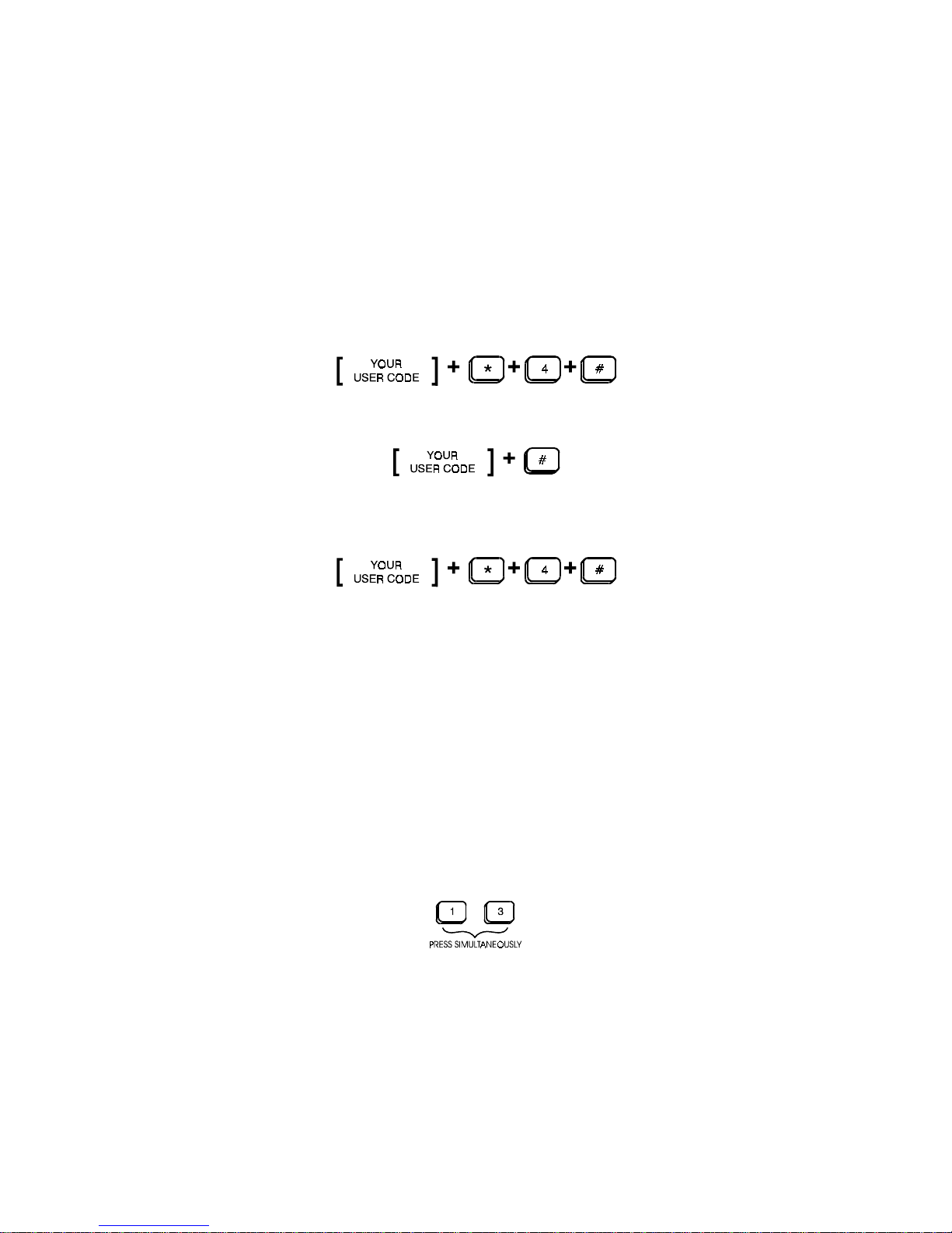
bypass a zone, enter your user code, then enter the number of the
zone to be bypassed (in this case 3), then the (#) key.
All the other burglary zones except zone 3 will ARM and the LCD
display will scroll through ARMED, BYPASSED and ZONE 3. The LED
keypad's Status light and all active zone lights will be lit. Zone 3 is now
deactivated. If the window is closed and opened again, an alarm
condition will not result, as this burglary zone will be bypassed until
the system is disarmed. When the system is disarmed the bypass is
removed. Additional zones may be bypassed in the same manner, by
adding their zone numbers before pressing the (#) key.
If your installer has programmed your system to allow bypass-
ing of 24hr zones, the bypass must be removed by arming and
disarming the system.
NOTE: For safety concerns, Fire zones can not be bypassed
Bypassing a Group of Zones
The system may have been configured to allow bypassing all interior
zones easily with a simple command. The sequence for Group Bypass
is as follows:
Group Bypassing is normally used to turn the alarm system
"On" while remaining in the protected area.

9
Instant/Delay Mode
Your system will normally arm in the Delay Mode when leaving the
premise. This will delay arming, allowing time to exit. When entering,
the alarm will be delayed allowing time to disarm the system. The
audible warning device will sound during the entrance delay remind-
ing you to disarm the system. The Instant Mode is primarily used in
residences. If this is desired, the key sequence is as follows:
If a zone(s) are to be bypassed in conjunction with entering the Instant
mode or the group bypassing is desired simply enter the zone
number(s) or the [* 1] prior to the [*] key in the sequence above.
Arming/Disarming Reports By User
The Arming and Disarming by user code identifies the user who
disarms and arms the system. This is accomplished by assigning an
individual user code to each of the eight possible users. The primary
user code is always reported as user one. Seven additional secondary
user codes report as user 1-7. Select secondary codes as shown in
Changing Code(s) From the Keypad Section.
Testing the Communicator
Your installer should instruct you on how to test , and how often to test
the communicator portion of your system. Various central monitoring
stations have different procedures for testing the communicator. Your
installer is familiar with this procedure.

10
Testing Your System
The system should be tested weekly. The local system can be tested
to verify that the system components are functioning by using the
following sequence.
Starts the Test mode
Arms the system and tests the alarm output. This sequence gives a
short bell blast and activates Alarm Memory.
This final sequence must be entered to return to Normal
During the test each door contact, motion detector, etc. should be
violated which will cause a short blast from the siren output. The Entry/
Exit delays are shortened to 4 seconds during the test.
The test is terminated by reentering the same sequence.
Smoke Detector Reset
Professional quality smoke detectors are designed to latch into alarm
condition and must be manually reset. Your control panel can be
programmed to reset this device following an alarm condition by
simultaneously pressing the "1" KEY + "3" KEY on the keypad.

11
Setting Chime Mode
Your installer may have designated certain burglary zones to briefly
activate the mini-sounder contained in each keypad. These zones
typically annunciate that a door has been opened or closed while the
panel is in the disarmed mode.
To turn the Chime feature On" use the key sequence shown
below.
Enter the sequence again to turn the feature "Off".
Fault Condition
A Fault Condition could, if unheeded, potentially render your system
inactive. If such a fault should occur it will be indicated by a flashing
green READY light, a TROUBLE message on the LCD display, and
an audible warning tone at the keypad. The LED keypad indicates this
Fault condition with the "STATUS" LED flashing with the audible tone.
To identify the nature of the Fault Condition, press and HOLD the
ENTER key. This will also silence the audible warning. Fault
conditions will show on the LED or LCD displays. The LED display
will indicate the trouble condition by flashing the appropriate zone
LED (see following chart). The LCD display will now indicate the
nature of the problem and it will scroll through the problems if there
are more than one. Discuss with your installer what action to take if
a problem should occur. If a trouble condition occurs on a fire zone,
call your installer for service since an important part of your system
is out of order.
The Table on the next page shows the LCD keypad messages and the
LED Zone numbers 1-4 for each of the Fault Conditions:

12
LED KYPD LCD KYPD PROBLEM
Status LED Green READY
Flashing LED Flashing Trouble Condition Exists
Zone #1 AC OFF: Indicates the AC power to your alarm
system has been disrupted.
Zone #2 LOW BATTERY: Indicates a low battery condition
Zone #3 TROUBLE: Indicates zone trouble condition
Zone #4 COMM FAIL: Indicates a failure to communicate
with Central Station.
The Zone in Trouble will show constantly IF the Trouble condition is
a Fire or Burglary trouble. The keypad will display the zone in Trouble.
The LCD will scroll each of the zone(s) and the LED keypad will light
the appropriate zone LED.
IT IS IMPORTANT FOR YOUR SAFETY THAT YOU
HAVE YOUR INSTALLER CORRECT ANY FAULTS AS
SOON AS POSSIBLE.
Duress (Ambush)
Your installer may have programmed a Duress code to use during a
holdup when youre ordered to disarm your system. When used, a
silent alarm is transmitted to the central monitoring station. Enter your
Duress Code, then press the [#]. The system will disarm and a silent
alarm will be transmitted. This code replaces user number 7 and can
be changed as shown on page 13.
NOTE: This function will only operate during a disarm
command.
Normal Disarm
Duress Disarm

13
Emergency Alarm Key Pairs
There are four special emergency codes that can be initiated at the
keypad. THESE EMERGENCY ALARM KEY PAIRS MUST BE
PRESSED SIMULTANEOUSLY, (a feature designed to minimize false
alarms).
The special LCD keypad key pair combinations are marked with a
circle, square, diamond, or triangle.
Consult your installer/dealer as to which one(s) of these are used, if
any, and which combination initiates which alarm. The special
symbols above and between the specific rows are to help you identify
which keys to press in case of an emergency situation.
Keypad Symbol Assigned Function
●
Circle Not Used _____________
■
Square Not Used _____________
◆
Diamond Not Used _____________
▲
Triangle Not Used _____________

14
Changing User Code(s) From The Keypad
Changing User Codes
User codes are changed using the primary user code (User #1) and
the sequence shown below.
The sequence uses the [Primary Code], [ * ], [ 7 ], [ * ][ User # ],
The four digits for the new code and then [#]. Vadid "User #'s" are
digits 1-8.
This example shows user #2 being changed or added to the system
as "9886".
User code number 2 is now programmed as "9886" into your system.
Additional users may be changed or added to the system using the
same sequence with the desired user number and four digit code.
Deleting Secondary User Codes
Sometimes it may be necessary to delete a secondary user code. Use
the same key sequence as above omitting the four digits for the new
code:
Example: User 2 code deleted.

15
Remote Telephone Access
If your installer has included this feature, you have the ability to check
on the status of your system and change the status when away from
home.
The SP850 control panel can be interrogated and status changed
from a remote touchtone telephone. The system will respond with a
series of beep tones to indicate whether the system is "Armed", "Ready
to Arm", "Not Ready", "In Alarm" or "System Trouble" condition.
In the case of an answering/fax machine on site, or phone
company provided answering service the following is important
to remember:
The "Ring Count" must be counted at the panel until it equals the
programmed value in location 144. Subsequent calls to the site
followed by a hangup and then redial before the line is taken by
the answering/fax equipment will be required before the panel will
answer.
To Use:
Call the premises telephone number.
Allow the phone to ring the proper number of times. Your installer will
set this at the time of installation.
The system will answer, wait about 5 seconds for a long tone.
Now enter your user code using the [#] sign for each digit. Pause
slightly between digits.
As an example, if your code was [2346]:
Tap [##] pause [###] pause [####] pause [######]. If you
enter the correct code you will hear a series of tones indicating your
system's status.
Number of tones = System Status
1 = Armed 2 = Ready to Arm 3 = Not Ready 4 = Alarm
5 = Trouble Note: Combinations of status conditions are possible.
To alter the status, simply press [###]. A new series of tones will tell
you the new status. If the status is changed from Not Ready, the
system will be Armed with a faulted zone in the Bypassed condition.
To hang up when the system is in the desired state press [#####].

16
Evacuation Plan
The National Fire Protection Agency recommends the following guide-
lines to be prepared for an actual fire.
1. Draw a floor plan of the building marking all doors and windows.
2. Evaluate all possible escape routes from building, trying each
route.
3. Select two (2) escape routes from each room.
4. Second floor rooms should have a rope ladder that reaches the
ground.
5. Draw a sketch of the escape route and familiarize everyone in the
home with it.
6. Select a meeting place outside where everyone is to report.
7. Practice the escape plan with everyone in household.
8. Advise the local fire department that a fire alarm system is installed.
FOR MORE INFORMATION WRITE:
NFPA
1 Battery March Park
Quincy, MA 02269
APPROVAL OF FIRE AUTHORITY DOES NOT INCLUDE
BURGLAR INSTALLATION OR EQUIPMENT.
FOR TECHNICAL ASSISTANCE PLEASE CONTACT YOUR
INSTALLER/DEALER

17
WARRANTY AND LIABILITY LIMITATIONS AND DISCLAIMER
LIMITED WARRANTY
Sentrol, Inc. warrants to the purchaser that under normal use and service, its products will be free
from defects in material and workmanship as follows: Control Panels and accessories - 24
months from date of manufacture; Sensors and accessories - 60 months from date of manufac-
ture. Sentrol, Inc.’s warranty obligation is limited to repairing or replacing (at Sentrol, Inc.’s sole
option) equipment which has been, during the warranty period and not more than thirty 30 days
after discovery, reported to Sentrol, Inc. as defective in material or workmanship and is so found
to be by Sentrol, Inc. upon inspection. For the purposes of this Warranty, Purchaser refers to
wholesale purchaser, installer and retail purchaser. Retail purchaser must, however, in the case
of defect, contact the person or entity who installed and maintains the product who in turn should
contact Sentrol, Inc. in accordance with the terms of this Limited Warranty.
Examination and repair or replacement of such equipment will be performed at Sentrol, Inc.’s.
facilities located in Hickory, North Carolina with no charge to purchaser for service time expended,
except as otherwise stated in this Warranty Limitations and Disclaimer. Equipment to be
examined, replaced or repaired at Sentrol, Inc.’s facilities must be returned to Sentrol, Inc. by
purchaser within the warranty period, insurance and transportation charges prepaid. Prior to the
return of the equipment, wholesale purchasers or installers shall obtain a return authorization
number from Sentrol, Inc.’s Customer Service Department. Retail purchasers are to contact the
person or entity who installed and maintains the product. Under no circumstance Sentrol, Inc. will
be responsible for expenses or labor incurred in removing and reinstalling its products from the
retail purchaser’s location. If examined equipment is found not to be defective or is not for some
other reason within the warranty coverage, Sentrol, Inc.’s service time expended will be charged
to purchaser.
Purchaser shall be responsible for all maintenance, service, replacing expendable parts, making
minor adjustments and performing operating checks, all in accordance with procedures outlined
in Sentrol Inc.’s operation manual. This Warranty shall not apply to any product failure that results
from purchaser’s failure to properly maintain, service, adjust, inspect and test the product in
accordance with Sentrol, Inc.’s operation manual.
WARRANTY LIMITATION AND EXCLUSION
The repair or replacement of any product under this Warranty Limitation and Disclaimer shall in
no event extend the term of the warranty beyond the original term set forth herein.
Sentrol, Inc. will have no further warranty obligation under this agreement if the equipment is
subject to tampering, abuse, misuse, electronic disruption, negligence, accident, flood, fire, acts
of God, improper installation, application or programming, improper maintenance or repair,
alteration, repair or installation by an unauthorized installer or repair facility, improper storage,
transportation or handling, or if purchaser fails to perform any of the procedures set forth in the
manual, and/or instruction sheet; specifically, the equipment must have been installed in
accordance with the instructions and operated in accordance with the instructions. In particular,
the unit must be programmed for regular test and the tests must be conducted on a regular basis,
but no less often than once per week.
This Warranty does not apply to components or parts manufactured by any person or entity other
than Sentrol, Inc.
Any repair or replacement of product within this Warranty must be performed by Sentrol, Inc.

18
DISCLAIMEROFWARRANTIES
THE WARRANTY PRINTED ABOVE IS THE ONLY WARRANTY APPLICABLE TO THIS
PURCHASE. ALL OTHER WARRANTIES, EXPRESS OR IMPLIED, INCLUDING, BUT
NOT LIMITED TO, THE IMPLIED WARRANTY OF MERCHANTABILITY AND FITNESS
FOR A PARTICULAR PURPOSE ARE DISCLAIMED.
NO OTHER PERSON OR ENTITY HAS BEEN AUTHORIZED BY SENTROL, INC. TO
MODIFYOR CHANGETHE TERMSOF THISWARRANTY. ANY AFFIRMATIONOF FACT
OR PROMISE MADE TO THE PURCHASER WHICH RELATES TO THE GOODS SOLD
UNDER THIS AGREEMENT SHALL NOT BE REGARDED AS A PART OF THE BASIS OF
THE BARGAIN AND SHALL NOT BE DEEMED TO CREATE AN EXPRESS WARRANTY
THAT THE GOODS SHALL CONFORM TO THE AFFIRMATION OR PROMISE. ANY
DESCRIPTION OF THE GOODS SOLD UNDER THIS AGREEMENT SHALL NOT BE
REGARDED AS A PART OF THE BASIS OF THE BARGAIN AND SHALL NOT BE
DEEMED TO CREATE AN EXPRESS WARRANTY THAT SUCH GOODS SHALL CON-
FORM TO THE DESCRIPTION.
SENTROL, INC. DOES NOT WARRANT THAT THE PRODUCT WILL MEET OR COMPLY
WITH THE REQUIREMENTS OF ANY SAFETY CODE REGULATION, STATUTE OR
ORDINANCE OF ANY STATE, MUNICIPALITY OR OTHER JURISDICTION.
LIMITATION OF LIABILITY
SENTROL, INC. DOES NOT, BY WAY OF THIS LIMITED WARRANTY OR IN ANY
OTHERMANNER,WARRANTORGUARANTEETHATTHISPRODUCTWILLPREVENT
PERSONAL INJURY OR PROPERTY LOSS. PURCHASER SHOULD TAKE ALL
REASONABLE AND AVAILABLE PRECAUTIONS IN PROTECTING HIS OR HER
SAFETY. IT IS UNDERSTOOD AND AGREED THAT SENTROL, INC.’S LIABILITY
WHETHER IN CONTRACT, IN TORT, UNDER ANY WARRANTY, IN NEGLIGENCE OR
OTHERWISE, SHALL NOT EXCEED THE RETURN OF THE AMOUNT OF THE PUR-
CHASE PRICE PAID BY PURCHASER AND UNDER NO CIRCUMSTANCES SHALL
SENTROL, INC. BE LIABLE FOR SPECIAL, INDIRECT OR CONSEQUENTIAL DAM-
AGES. THEPRICE STATEDFORTHEEQUIPMENTISACONSIDERATION INLIMITING
SENTROL, INC.’S LIABILITY. NO ACTION, REGARDLESS OF FORM, ARISING UNDER
THIS WARRANTY MAY BE BROUGHT BY PURCHASER MORE THAN ONE (1) YEAR
AFTER THE CAUSE OF ACTION HAS ACCRUED.
This Limited Warranty gives you specific legal rights and you may also have other rights
which vary from state to state. Some states do not allow limitation on how long an implied
warranty will last or the limitation or exclusion of incidental or consequential damages, so
the above limitations or exclusion may not apply to you, if not allowed by law.
Should purchaser have any questions with regards to this Warranty and Liability Limitations
and Disclaimer they should contact:
Sentrol, Inc.
1510 Tate Boulevard
Hickory, North Carolina 28601
(800)800-2626
This manual suits for next models
2
Table of contents
Other Arrowhead Keypad manuals