xILC450 Function Module Installation and Operations Manual
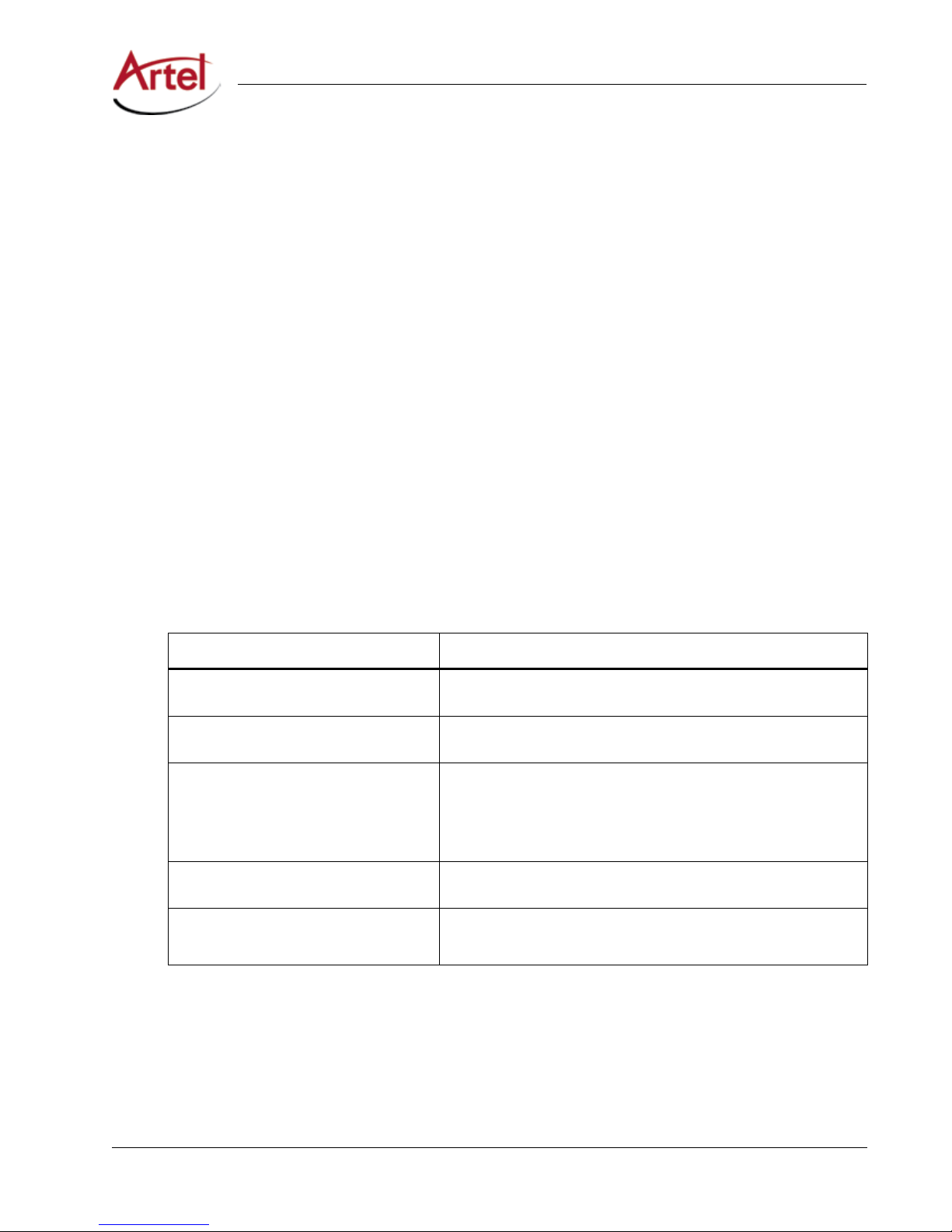
Symbols and Conventions
This manual uses the following symbols and conventions.
Caution
A caution means that a specic action you take or fail to take could cause harm to the equipment or
to the data transmission.
Warning
A warning describes an action you take or fail to take that could result in death, serious physical injury, or
destruction of property.
Note: Important related information, reminders, and recommendations.
Italics—used for emphasis, for indicating the rst occurrence of a new term, and for book titles
1. Numbered list—where the order of the items is important
• Bulleted list—where the items are of equal importance and their order is unimportant
Artel Customer Service
You can reach Customer Service by e-mail at customercare@artel.com or by telephone:
In the US call (800) 225-0228, then select 1 for technical support.
Outside the US call (978) 263-5775, then select 1 for technical support.
When requesting assistance, please be ready to provide the following information:
• Your name and telephone number
• Product model and serial number
• Brief description of the problem
• List of symptoms
• Steps you have already taken to try to resolve the problem
If the product is damaged
If any portion of the unit is damaged, forward an immediate request to the delivering carrier to perform an
inspection of the product and to prepare a damage report. Save the container and all packing materials until
the contents are veried.
Concurrently, report the nature and extent of the damage to Artel Customer Service so that action can be
initiated to either repair or replace the damaged items.
Do not return any items to Artel until you obtain instructions from Customer Service.
Report the problem or deciency to Customer Service along with the model number and serial number. Upon
receipt of this information, Artel will provide service instructions, or a Return Authorization Number and
shipping information.