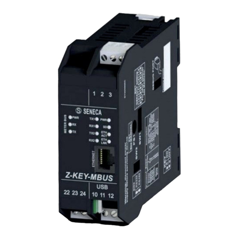
MI00589-1-EN INSTALLATION MANUAL 4/4
INSTALLATION REGULATIONS
The module has been designed for vertical installation on a DIN 46277 rail. For optimal operation and long life, adequate ven-
tilation must be provided. Avoid positioning ducting or other objects that obstruct the ventilation slots. Avoid mounting modules
over heat-generating equipment. Installation in the bottom part of the electrical panel is recommended.
These are open type devices intended for installation in a nal casing/panel that offers mechanical protection and protection
against the spread of re.
CAUTION
ELECTRICAL CONNECTIONS
CAUTION
To meet the electromagnetic immunity requirements:
- use shielded signal cables;
- connect the shield to a preferential instrumentation earth system;
- separate shielded cables from other cables used for power installations (transformers, inverters, motors, etc...).
10
11
12
GND
A (+)
B (-)
10
11
12
GND
RX
TX
22
23
24
MeterBUS+
MeterBUS+
Not Used
1
2
3
Vac/Vdc
Vac/Vdc
POWER SUPPLY RS485 SERIAL PORT
SW2 = OFF
RS232 SERIAL PORT
SW2 = ON
Meter-Bus PORT
Use only copper or copper-coated aluminium or AL-CU or CU-AL conductors
CAUTION
CONNECTION STANDARDS
MeterBUS is a non-polarized bus. For the connection it is possible to use a two-wire shielded telephone cable or an unshielded
duplex cable following the indications in the table.
If a shielded cable is used, this must be connected to earth only from the side of the Z-KEY-MBUS instrument.
Type of
installation
Maximum
speed
Connection
maximum distance
Connection
total length Type of cable
Small in house 38400 < 350 m < 1000 m 0.5 mm2, R < 30 Ω
Large in house 9600 < 350 m < 3000 m 0.5 mm2, R < 30 Ω
Small wide area 2400 < 1000 m < 3000 m 1.5 mm2, R < 90 Ω
IDC10 CONNECTOR
-
RS485GND
RS485A
RS485B
Power Supply AC / +
Power Supply AC /
IDC 10
1
The illustration shows the meanings of the various
IDC10 connector pins if signals are to be sent via
them directly.
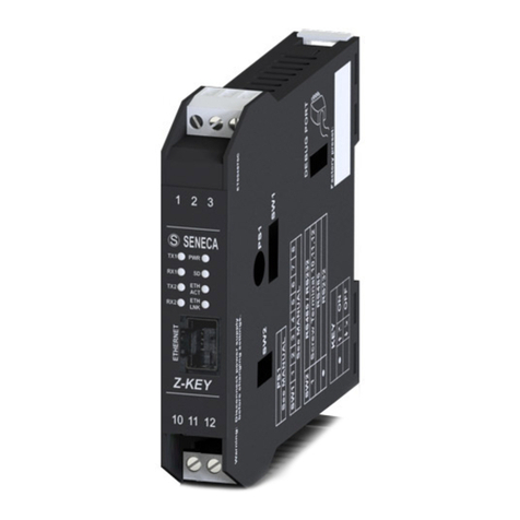
The device is normally in Pronet mode; in Pronet mode the device can be congured only through the Easy Setup 2 software.
In order to access the internal webserver it is necessary to put the device in Webserver mode using the Easy Setup 2 or
Seneca Device Discovery software. It is also possible to change the operating mode by pressing the side button following the
procedure:
To force webserver mode:
• Keep the “PS1” button pressed until all the LEDs go off
• Release the button
• The device restarts and the PWR and COM LEDs ash slowly to indicate webserver mode
To force Pronet mode:
• Keep the “PS1” button pressed until all the LEDs go off
• Release the button
• The device restarts and the PWR and COM LEDs stop ashing slowly to indicate Pronet mode
WEB SERVER AND PROFINET MODE (Z-KEY-MBUS-P)
