Artel PCS3 Manual

15A3356O
PCS®3
Procedure Guide
®
25 Bradley Drive
Westbrook, Maine USA 04092-2013
tel: 207-854-0860, toll free: 1-888-406-3463
fax: 207-854-0867
email: [email protected]
web: www.artel-usa.com

15A3356O
Note: This Guide applies to PCS®instruments with firmware
versions 7A2.XXX or 7A3.XXX, where “XXX” represents a three
digit number between 001 and 999. Changes for later versions
may be described in addenda and inserted following this page.
Document Number & Revision: 15A3356O
Document Revision Date: June 2017
Copyright © 2017 Artel, Inc.
Products are intended for use with the Artel PCS as applicable.
The Artel PCS and its components are covered by patents listed at www.artel-
usa.com/patents.
All Artel product Safety Data Sheets are available at www.artel-usa.com/support-
ordering.
All rights reserved. No part of this publication may be reproduced, stored in a
retrieval system, or transmitted, in any form or by any means, electronic,
mechanical, photocopying, recording, or otherwise, without the prior written
permission of the publisher. Printed in the United States of America.
Artel, the Artel logo and PCS are registered trademarks of Artel, Inc., Westbrook,
Maine.
Artel
25 Bradley Drive
Westbrook, ME 04092-2013
U.S.A.

15A3356O
TABLE OF CONTENTS
(Sections 1-5)
1.0 INTRODUCTION ……………………………………………………………………….1
2.0 INSTRUMENT PREPARATION
2.1 Location ..................................................................................................... 3
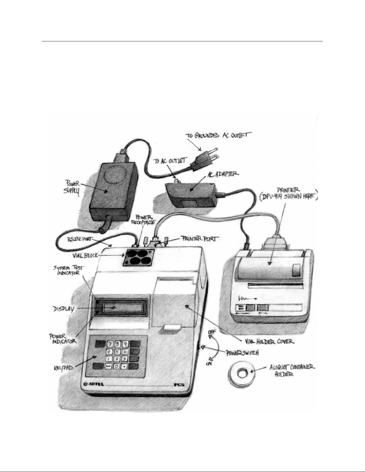
2.2 Set-up and Cabling Illustration ................................................................... 3
2.3 Cabling Procedures ................................................................................... 4
2.4 Seiko Printer .............................................................................................. 4
2.5 RS232 Port ................................................................................................ 5
3.0 REAGENT KIT
3.1 Contents of Standard Reagent Kit ............................................................. 7
3.2 Cleaning of PCS Vials ................................................................................ 8
3.3 Storage ...................................................................................................... 8
3.4 Disposal ..................................................................................................... 8
3.5 Ordering ..................................................................................................... 8
4.0 OPERATION
4.1 Instrument Keys and Operating Functions ................................................. 9
4.2 Initial Power-On Sequence ...................................................................... 10
4.3 Starting Pipette Calibration ...................................................................... 10
4.4 Inserting the Blank Vial ............................................................................ 13
4.5 Entering Pipette ID Number ..................................................................... 14
4.6 Entering Pipette Volume .......................................................................... 14
4.7 Pipetting Sample Solution ........................................................................ 15
4.8 Pipetting Additional Samples ................................................................... 17
4.9 Eliminating Sample Readings and Reprinting Results ............................. 17
4.10 Performing Additional Calibrations In One Vial ........................................ 18
4.11 Continuing a Calibration Run with Another Vial ....................................... 20
4.12 Calibrating an Adjustable Volume Pipette at Multiple Volumes ................ 20
4.13 Suggested Initial Tolerance Limits ........................................................... 21
5.0 INSTRUMENT CAL A AND CALIBRATION
5.1 Instrument CAL A .................................................................................... 23
5.2 Instrument Calibration ............................................................................. 23
5.3 Instrument Calibration Summary ............................................................. 27

15A3356O
TABLE OF CONTENTS
(Sections 6-App. F)
6.0 INSTRUMENT SETUP
6.1 Instrument Setup Menu............................................................................ 29
6.2 Setting Date ............................................................................................. 30
6.3 Setting Time ............................................................................................. 30
6.4 Choosing Date Format ............................................................................. 31
6.5 Customizing the Printout Header ............................................................. 31
6.6 Computer Link Flags ................................................................................ 32
6.7 Serial Data Output (Data Collect Flag) ..................................................... 33
6.8 Choose Nomenclature ............................................................................. 34
6.9 Display Uncertainty .................................................................................. 35
6.10 Signature Block ........................................................................................ 36
7.0 TROUBLESHOOTING
7.1 Instrument Diagnostics Menu .................................................................. 37
7.2 Troubleshooting Guide ............................................................................. 40
8.0 SYSTEM MAINTENANCE
8.1 Preventive Maintenance .......................................................................... 45
8.2 Instrument Calibration .............................................................................. 45
8.3 Removal of Rear Access Cover ............................................................... 45
8.4 Maintenance Log Sheet ........................................................................... 46
9.0 WARRANTY AND SERVICE
9.1 Warranty Statement ................................................................................. 47
9.2 Return and Repair ................................................................................... 47
APPENDICES
Specifications ....................................................................................................... A
PCS Printouts ....................................................................................................... B
Formulas Used to Calculate Group Statistics ....................................................... C
ASCII Character Set ............................................................................................. D
Alphabetic Character Entry ................................................................................... E
Number of Samples Per Vial ................................................................................ F
Consumables ....................................................................................................... G

15A3356O 1
1.0 INTRODUCTION
Accuracy and precision in volumetric measurement and transfer are essential to
all laboratories concerned with maintaining quality and productivity. Pipette
performance can vary significantly over time, and conformance to specified
accuracy and precision levels cannot be taken for granted.
Employing a colorimetric method and a high performance photometer, the PCS®
allows the user to accurately, precisely, quickly, and easily measure the
dispensed volume from any pipette (from 0.1 μL to 5000 μL). Measurements
made with the Artel Pipette Calibration System (PCS®) are traceable to the
International System of Units (SI) through reference standards developed and
maintained by the National Institute of Standards and Technology, USA (NIST).
The volume of liquid delivered is immediately calculated and displayed for each
data point. A Printout is generated displaying the volume of each sample and the
group statistics. The Printout includes such information as pipette ID, operator ID,
time, temperature, and date to assist with effective record keeping.
Additionally, by providing immediate feedback to the user, the PCS is an effective
tool for improving pipetting technique.
With a minimal amount of training an operator can calibrate pipettes both when
and where needed, improving workflow, quality, and efficiency in the laboratory.
This manual provides step-by-step instructions for all major operations to assist
the user to be up and running more quickly.

15A3356O 2
This Page Intentionally Left Blank

15A3356O 3
2.0 INSTRUMENT PREPARATION
2.1 Location
The Instrument should be located in an area that is out of direct sunlight
and away from local heat sources (e.g. an oven or heat vent).
2.2 Set-up and Cabling Illustration

15A3356O 4
2.3 Cabling Procedures
2.3.1 Connecting the Instrument to Power
The Instrument requires a three-prong electrical receptacle
supplying single-phase power from 100-250 VAC, 50/60 Hz in
which to plug the Power Supply. The same power source should be
used for the Instrument and the Printer. This power line should be
free from transients or voltage variations caused by other
equipment such as water baths or refrigerators.
Make sure that the Instrument Power Switch is off. Plug one end of
the Power Cord into the Power Supply and the other end of the
Power Cord into a grounded AC outlet. Insert the remaining plug
into the power receptacle found at the rear of the Instrument.
IMPORTANT Ensure that all above connections are firmly in place.
2.3.2 Connecting the Seiko Printer to Power
NOTE: If the STAR Dot Matrix Printer is being used, please refer to the STAR Printer
User’s Manual for printer connection and operation.
Plug the Printer AC adapter into an appropriate receptacle.
Plug the remaining end of the adapter into the power receptacle
located at the rear of the Printer.
2.3.3 Connecting the Printer to the Instrument
Make sure the Instrument and Printer are turned off. Plug one end
of the Printer cable into the Printer and the other into the
Instrument.
IMPORTANT When the Instrument and Printer are connected, the Instrument must be powered on to
operate the Printer.
2.4 Seiko Printer
2.4.1 Controls and Indicators:
Power Switch. When slid to the ON position, power is supplied to
the Printer and the POWER and ON LINE indicators illuminate.
When there is no paper loaded, the OFF LINE indicator flashes.

15A3356O 5
Paper Feed Switch. Pressing this switch feeds the paper
continuously. Paper feed will work only when the OFF LINE
indicator illuminates or flashes.
On Line/Off Line/Paper End Switch. Pressing this switch shifts
the Printer from ON LINE to OFF LINE and vice versa. When ON
LINE, the Printer is ready to receive instructions from the
Instrument. The Printer cannot be turned ON LINE if paper is not
loaded.
2.4.2 Loading Printer Paper
Turn the Power Switch to the ON position.
Open the paper cover located on the top right hand side of the
Printer.
Cut the end of the paper roll cleanly and squarely.
Insert the end of the paper into the inlet at the bottom of the paper
holder until the auto-loader catches it and feeds it through. The
outside of the roll is the printable surface for the thermal paper roll.
Close the paper cover.
NOTE: A red line will appear on both sides of the paper when the paper roll nears
depletion. This indicates that the paper roll should be changed.
2.4.3 Preparing the Printer for Pipette Calibration
Once the paper roll is in place, the Instrument and the Printer can
be turned ON. When the ON LINE light is green, the printer is ready
for operation.
NOTE: Refer to the printer operation manual for more detailed information.
2.5 RS232 Port
Refer to Section 6.7, “Serial Data Output,” for information on use of the
RS232 port.

15A3356O 6
This Page Intentionally Left Blank

15A3356O 7
3.0 REAGENT KIT
3.1 Contents of Standard Reagent Kit
Blank Reagent Vials:
(12) Prefilled with Blank Reagent.
Sample Solutions:
(1) Range 1: For pipette volumes
200 to 5000 μL
(1) Range 2: For pipette volumes
50 to 199 μL
(1) Range 3: For pipette volumes
10 to 49 μL
(1) Range 4: For pipette volumes
2 to 9 μL
NOTE: Range 5 for pipette volumes 0.5 to 1.9 μL, and Range 6 for pipette volumes 0.1 to 0.49
μL, are sold separately.
Sample Aliquot Containers:
(12) Used to contain an aliquot of Sample Solution.
Transfer Pipettes:
(12) Used to transfer an aliquot of Sample Solution into a Sample
Aliquot Container.
Calibration Standard:
(1) CAL A used for zeroing the Instrument daily.
Kit Inserts:
(1) Declaration of Traceability
(1) Lot Code Card (Refer to Section 4.3, “Starting Pipette
Calibration.”)

15A3356O 8
3.2 Cleaning of PCS Vials
To ensure that accurate and precise results are obtained during pipette
and PCS Instrument calibration, all vials should be free from fingerprints
and smudges prior to placement into the Vial Block to equilibrate.
Fingerprints and smudges that fall within the optical path will introduce
errors and cause inaccurate readings.
All PCS vials are cleaned and inspected prior to shipment. However, the
lower portion of the vials should be cleaned prior to use.
Recommended vial cleaning procedure:
3.2.1 Holding the vial by the cap, immerse the lower portion of the vial
(about 2.5 cm) into clean isopropyl alcohol.
3.2.2 Remove the vial from the alcohol and while wearing gloves gently
wipe the lower portion of the vial by rotating the vial against a lint
free wipe.
3.3 Storage
The Reagent Kit should be stored at room temperature (18 °C to 28 °C).
Avoid storage temperatures exceeding 32 °C. Kit components should be
stored in the dark to the extent practical.
NOTE: Reagents received frozen should be brought to room temperature and gently
inverted.
3.4 Disposal
Refer to Safety Data Sheet (SDS) for proper disposal. All PCS Reagents
are non-hazardous and aqueous-based.
3.5 Ordering
To place an order or request a product list, please contact Customer
Service at:
Email: [email protected]
Local: 207-854-0860
Toll Free: 888-406-3463
Fax: 207-854-0867

15A3356O 9
4.0 OPERATION
4.1 Instrument Keys and Operating Functions
YES Starts a procedure or is used as a positive response to a
question.
ENTER
Enters a numerical value such as the pipette ID number or
volume. It also can be used when checking adjustable
volume pipettes to signify a change to a new volume.
MENU
SCROLL Used to view the next question or a different question.
NO Used as a negative response to a question.
Enters a decimal point or period.
END OF
RUN
Terminates a pipette calibration run. Group statistics for
data collected up to that point of the procedure will be
printed.
CLEAR Clears the data entry window or corrects the most recent
invalid entry.
RESET
Halts the procedure and returns the system to the prompt:
Main Menu
Pipette Calibration?
Ends the calibration and the Blank Vial in use.

15A3356O 10
4.2 Initial Power-On Sequence
4.2.1 Turn on the Instrument and the Printer. Be sure the Printer is ON
LINE.
4.2.2 Before performing this procedure ensure that the Reagent Kit is at
the same temperature as the Instrument.
NOTE: If the kit has been moved from another location, depending on the difference in
temperature between the two locations, allow time for equilibration.
CAL A and Blank Vials should be loaded into the Vial Block at least
15 minutes prior to their use. Four vials at a time can be loaded into
the Vial Block. Inspect vials for smudges. If cleaning is necessary,
refer to Section 3.2, “Cleaning of PCS Vials.”
4.2.3 Upon power-on, the Instrument will perform a system test. The
following prompt will be displayed:
Main Menu
Pipette Calibration?
NOTE: To check the date and time, and to edit the header information on the Printout,
refer to Section 6.0, “Instrument Setup.”
4.3 Starting Pipette Calibration
4.3.1 At the prompt:
Main Menu
Pipette Calibration?
Press YES to begin the pipette calibration procedure.
The instrument will then check the temperature, and if it is outside
the specified range for proper operation (18 °C to 28 °C), the
following prompt will be displayed:
Temp. out of range
Continue? (Y/N)

15A3356O 11
If NO is pressed, the following prompt will be displayed:
Main Menu
Pipette Calibration?
If YES is pressed to continue with the calibration, there is no
certainty that the results the PCS obtains will meet the system
specifications.
The display will prompt to enter the Lot Code:
Enter Reagent Lot
Code: _
4.3.2 Enter the Lot Code. The Lot Code is shown on the Reagent Vials,
Reagent Kit insert, and on the exterior of the Reagent Kit box. The
Instrument maintains a library of up to 6 previously entered Lot
Codes. If this Lot Code matches one previously entered, proceed to
Section 4.3.3.
If the Lot Code does not match, the display will prompt:
Rgt Lot Code XXXXX
New Lot? (Y/N)
If the Lot Code was entered incorrectly, press NO and enter the
correct Lot Code.
Press YES if entering a new Lot Code. The Group Numbers found
on the correct side of the Lot Code Card for the instrument type will
need to be entered. Press ENTER after entry of each group of
digits. At the next prompt, enter the month and year of the
expiration date of the Reagent Kit as indicated on the Lot Code
Card in the format mmyy (e.g. 0811 for August 2011).
The following prompt will be displayed:
Lot Code: XXXXX
Correct? (Y/N)
Press YES to confirm.

15A3356O 12
4.3.3 The Instrument will perform a brief self-calibration. The following
prompt will be displayed:
Self-Calibration
Please Wait
Followed by:
Insert
CAL A Vial
IMPORTANT Use the CAL A from the Reagent Kit in use, not the CAL A from the Instrument
Calibrator Kit. The label for this vial should face toward the front of the Instrument,
with the vertical line on the vial facing forward.
Remove the CAL A Calibration Standard from the Vial Block.
4.3.4 Open the Vial Holder Cover and insert CAL A into the Vial Holder,
pressing it down until it meets the bottom of the Vial Holder. Never
remove the cap of the CAL A Calibration Standard.
The following prompt will be displayed:
Please
Close the Cover
4.3.5 Close the Cover.
The Instrument will then perform a Zero Check while displaying:
PCS Zero Check
Please Wait
The following prompt will be displayed:
Please
Remove Vial
4.3.6 Remove CAL A and place it into the Reagent Kit for future use.

15A3356O 13
The following prompt will be displayed:
Remove Cap and
Insert Blank
4.4 Inserting the Blank Vial
IMPORTANT Blank Reagent Vials must be handled with care.
Each vial contains a predetermined amount of liquid and spillage will
reduce accuracy.
The lower portion of the Blank Vial is a part of the optical path and
smudges will decrease the accuracy of the results. Touching this region
should be avoided.
To ensure a consistent optical path, once the Blank Reagent Vial has
been inserted into the Instrument it must not be turned, moved or
removed until the calibration procedure is completed for all pipettes to be
calibrated using that vial.
4.4.1 Remove a Blank Reagent Vial from the Vial Block. The Blank
Reagent is light blue in color.
4.4.2 Remove the cap, open the Vial Holder Cover and insert the Blank
Reagent Vial into the Vial Holder, pressing it down until it contacts
the bottom of the Vial Holder.
The following prompt will be displayed:
Please
Close the Cover
4.4.3 Close the Vial Holder Cover. The Instrument will read the Blank
while displaying:
Reading Blank
Please Wait
After the Blank reading is complete, the next prompt will instruct to
enter an Operator ID:
Enter Operator ID:
1

15A3356O 14
Enter the Operator ID (not exceeding 20 digits or characters) for
this calibration and press ENTER. This ID appears on the Printout.
For alphabetic character entry, see Appendix E. If the ID is entered
incorrectly, press CLEAR and enter the correct ID.
4.5 Entering Pipette ID Number
At the prompt:
Enter Pipette ID:
_
Enter the Pipette ID (not exceeding 20 digits or characters) for this
calibration and press ENTER. This ID will be printed on the PCS Printout
for pipette cross-referencing, and as a hard copy record. For alphabetic
character entry, see Appendix E.
The Instrument will print the information just entered and display:
*** Printing ***
Please Wait
Followed by:
Enter Pipette
Volume: _ uL
4.6 Entering Pipette Volume
Enter the volume (in microliters) to be dispensed, and press ENTER. The
CLEAR key can be used to correct an entry error prior to pressing the
ENTER key.
NOTE: This volume must be entered in microliters ranging from 0.1 μL through 5000 μL.
The number of samples that can be added at this pipette volume in
this vial will be displayed:
XX Left this Vial
Proceed? (Yes/No)
Press YES. The following prompt will be displayed:
Range X
Please Wait
The Instrument will take a final Blank reading, and then prompt:

15A3356O 15
Range X
Pipette Sample # 1
4.7 Pipetting Sample Solution
NOTE: The number of data points that are collected to calibrate a pipette depends on the
requirements of the laboratory and its calibration policy. Additionally, the technique used
to check the pipettes should coincide with the method for its general use.
4.7.1 Locate the appropriate Sample Solution in the Reagent Kit. Mix the
contents by inverting the bottle several times before removing the
cap.
IMPORTANT The proper range of Sample Solution for the pipette volume to be tested must be
used. Each kit contains bottles of Sample Solution corresponding to four different
pipette volume ranges. (Refer to Section 3.1, “Contents of Standard Reagent Kit.”)
If the improper Sample Solution has been pipetted into a Blank Reagent Vial, the
results obtained will not be valid and that vial is no longer usable and should be
discarded.
4.7.2 Using a disposable Transfer Pipette, transfer an aliquot of Sample
Solution into a Sample Aliquot Container. Transfer Pipettes and
Sample Aliquot Containers are found in the Reagent Kit. Place the
container into the Aliquot Container Holder to reduce the possibility
of spillage. Place the cap lightly on the Sample Aliquot Container to
avoid evaporation, and replace the cap on the Sample Solution
Bottle to avoid evaporation.

15A3356O 16
Transfer only enough Sample Solution for use in half-hour
increments. The total volume of Sample Solution required depends
on the sample volume and the total number of data points being
generated. The volume graduations on the Transfer Pipette as well
as the 1 mL mark on the Sample Aliquot Container can be used as
a guide.
IMPORTANT When handling open Blank Reagent Vials and open Sample Solutions, be very
careful not to spill any liquid on or along the edges of the Instrument’s keypad.
When calibrating a pipette, there is an inevitable linkage between
operator technique and pipette performance. For meaningful
results, it is recommended that standard laboratory pipetting
technique be used and that specific pipette manufacturer's
instructions are followed. Using the PCS for training purposes
provides the opportunity to improve technique and to optimize
pipetting accuracy and precision. For additional technique
instructions, contact ARTEL Technical Support, and refer to the
information included in the back of the Procedure Guide.
4.7.3 Aspirate the Sample Solution from the Sample Aliquot Container
with the pipette to be calibrated, using standard pipetting technique.
Place the cap lightly back on the Sample Aliquot Container between
samplings to avoid reagent evaporation.
4.7.4 Lift the Instrument Vial Holder Cover and dispense the Sample
Solution into the Blank Reagent Vial.
IMPORTANT The Sample Solution should be dispensed against the inside wall of the vial with
the pipette tip placed above the meniscus but below the shoulder of the Blank
Vial. The vortex mixing action will wash the solution from the inside wall of the vial.
4.7.5 Once the sample is dispensed, carefully withdraw the pipette and
close the Vial Holder Cover.
The Instrument will then display:
Mixing Sample # 1
Please Wait
This manual suits for next models
1
Table of contents
Other Artel Laboratory Equipment manuals