Infors HT Multifors 2 User manual

Operating Manual
2018-03-28
Multifors 2
Parallel Bench-top Bioreactor
Dok-ID: V. 04.01 - Original

Page 2 of 211 28 March 2018
Infors AG
Headoffice, Schweiz
Rittergasse 27
CH-4103 Bottmingen
T +41 (0)61 425 77 00
F +41 (0)61 425 77 01
info@infors-ht.com
service@infors-ht.com
Infors GmbH
Dachauer Str. 6
D-85254 Einsbach
T +49 (0)8135 8333
F +49 (0)8135 8320
infors.de@infors-ht.com
Infors UK Ltd
The Courtyard Business Centre
Dovers Farm, Lonesome Lane,
Reigate
Surrey, RH2 7QT, UK
T +44 (0)1737 22 31 00
F +44 (0)1737 24 72 13
infors.uk@infors-ht.com
Infors Sarl
2, rue du Buisson aux Fraises
Bâtiment D13
F-91300 Massy
T +33 (0)1 69 30 95 04
F +33 (0)1 69 30 95 05
infors.fr@infors-ht.com
www.infors-ht.fr
Infors Benelux BV
Markweg 9-A, NL-6883 JL
Velp (GLD)
P.O. Box 125, NL-6880 AC
Velp (GLD)
T +31 (0)26 369 31 00
F +31 (0)26 369 31 09
infors.bnl@infors-ht.com
Infors USA Inc.
9070 Junction Drive, Suite D
Annapolis Junction, MD20701
T +1 301 362 3710 /
T +1 855 520 7277 (toll-free USA)
F +1 301 362 3570
infors.usa@infors-ht.com
www.infors-ht.us
Infors Canada
8350 rue Bombardier
Anjou, Quebec
Canada H1J 1A6
T +1 514 352 5095
F +1 514 352 5610
infors.ca@infors-ht.com
Infors Bio-Technology
(Beijing) Co., Ltd.
Room 505C, Building 106
Lize Zhongyuan
Wangjing New Industrial Zone
Chaoyang District, Beijing
100102 P.R. of China
T +86 10 51652068
F +86 10 64390585
info@infors-ht.com.cn
Infors South East Asia
16, 1st Floor, Taman City
MY-51200 Kuala Lumpur
Malaysia
T +603 625 771 81
F +603 625 067 48
info@infors-ht.com.my
Infors LATAM Ltda.
Rua Dr. Alceu de Campos
Conjunto 205
CEP: 04544-000
São Paulo – SP
Brasil
T +55 (11) 95304-0201
F +55 (11) 98585-5334
Infors.br@infors-ht.com
Contact details of our local dealers worldwide can be found
on our website.
www.infors-ht.com
Engineering and production in Switzerland

Multifors 2 - Parallel Bench-top Bioreactor
Table of Contents
28 March 2018 Page 3 of 211
1General Information ............................................................... 8
1.1 About this Manual .......................................................... 8
1.2 Symbols ......................................................................... 9
1.2.1 Safety Instructions .......................................... 9
1.2.2 Hints and Recommendations ......................... 9
1.2.3 Specific Safety Instructions .......................... 10
1.3 Limitation of Liability .................................................... 11
1.4 Copyright Protection .................................................... 11
1.5 Spare Parts .................................................................. 12
1.6 Terms of Guarantee ..................................................... 12
1.7 Customer Service ........................................................ 12
1.8 Declaration of Conformity ............................................ 12
2Safety .................................................................................... 13
2.1 Responsibility of the Operator ..................................... 13
2.2 Requirements for Qualified Personnel ......................... 14
2.2.1 Unauthorised Persons .................................. 15
2.3 Conventional Use of the Equipment ............................ 16
2.4 Personal Protective Equipment ................................... 17
2.5 Particular Hazards ....................................................... 19
2.6 Environmental Protection ............................................. 22
2.7 Adhesive Labels / Signs / Symbols ............................. 22
3Technical Data ...................................................................... 24
3.1 Equipment Dimensions ................................................ 24
3.2 Dimensions Culture Vessels and Vessel Holder ......... 25
3.3 Weights ........................................................................ 27
3.4 Service Requirements ................................................. 28
3.4.1 Electrical ....................................................... 28
3.4.2 Water IN ....................................................... 28
3.4.3 Water OUT ................................................... 28
3.4.4 Gas(es) IN .................................................... 28
3.4.5 Exit Gas ........................................................ 29
3.5 Specifications ............................................................... 30
3.5.1 Operating Unit .............................................. 30
3.5.2 Vessels ......................................................... 30
3.5.3 Stirrer Drive System bacterial Version ......... 32
3.5.4 Stirrer Drive System Cell Culture Version .... 33
3.5.5 Temperature ................................................. 35
3.5.6 Gassing Bacterial System ............................ 36
3.5.7 Gassing Cell Culture System ....................... 37
3.5.8 Antifoam ....................................................... 38
3.5.9 pH ................................................................. 38

Multifors 2 - Parallel Bench-top Bioreactor
Table of Contents
Page 4 of 211 28 March 2018
3.5.10 pO2 ................................................................39
3.5.11 Pumps ...........................................................40
3.5.12 Sterile Filters .................................................41
3.6 Operating Conditions ...................................................42
3.7 Emissions .....................................................................42
3.8 Identification Plate ........................................................43
4Setup and Function ..............................................................44
4.1 Basic Unit .....................................................................44
4.1.1 Main Switch ..................................................46
4.1.2 Mains Connection .........................................46
4.1.3 Water Connections .......................................47
4.1.4 Gas Connections ..........................................47
4.1.5 Connections of the Exit Gas Cooler and
Control Valve ................................................47
4.1.6 Connection of the Sparger ............................49
4.1.7 Pumps ...........................................................50
4.2 Operating Panel ...........................................................52
4.2.1 Monitor Keys .................................................52
4.2.2 Operating Panel Connections .......................53
4.3 Vessels, Vessel holder & Transport Frame .................54
4.3.1 Vessel for bacterial Cultures .........................55
4.3.2 Vessel for Cell Cultures ................................57
4.3.3 Baffle Cage ...................................................58
4.3.4 Vessel Top Plate Ports and Configuration ...60
4.3.4.1 Top Plate with nominal Width
55/70 ............................................ 64
4.3.4.2 Vessel Top Plate with nominal
Width 70 ....................................... 65
4.3.4.3 Vessel Top Plate with nominal
Width 90 ....................................... 66
4.4 Temperature Control System .......................................67
4.5 Drive and Stirrer ...........................................................68
4.5.1 Drive Shaft for bacterial Cultures ..................68
4.5.2 Drive Shaft for Cell Cultures .........................69
4.5.3 Impellers .......................................................70
4.6 Gassing System ...........................................................71
4.6.1 Gassing Strategy ..........................................72
4.6.2 Gas Entry ......................................................72
4.6.3 Exit Gas and Exit Gas Cooler .......................76
4.7 Accessory Kit ...............................................................77
4.7.1 Antifoam Sensor ...........................................77
4.7.2 Reagent Bottles ............................................80

Multifors 2 - Parallel Bench-top Bioreactor
Table of Contents
28 March 2018 Page 5 of 211
4.7.3 Sampling System ......................................... 81
4.7.3.1 Super Safe Sampler, aseptic
Sampling System .......................... 81
4.7.4 Starter-Kit ..................................................... 86
4.8 Field of Application ...................................................... 87
4.9 Types ........................................................................... 87
5Transport, Packaging and Storage .................................... 88
5.1 Safety Instructions for Transport .................................. 88
5.2 Transport Inspection .................................................... 88
5.3 Packaging .................................................................... 89
5.4 Transport ...................................................................... 90
5.5 Storage ........................................................................ 91
5.5.1 Storage of the Equipment in General ........... 91
5.5.2 Storage of the Reagent Bottles and Hoses .. 92
5.5.3 Storage of Sensors ....................................... 92
6Installation and Initial Operation ........................................ 93
6.1 Safety ........................................................................... 93
6.2 Location Requirements for Installation ........................ 94
6.2.1 General Information ...................................... 94
6.2.2 Minimum Spacing ......................................... 95
6.2.3 Supply Lines ................................................. 95
6.2.3.1 Air/Gas .......................................... 95
6.2.3.2 Exit Gas ......................................... 96
6.2.3.3 Water Inlet ..................................... 97
6.2.3.4 Water outlet ................................... 97
6.2.3.5 Electric Power Supply ................... 98
6.3 Mounting the Operating Panel ..................................... 99
6.4 Connecting the Operating panel to the Basic Unit..... 100
6.5 Connecting the Master Unit with the Satellite Unit(s) 101
6.5.1 Mounting the Water Connection Set for 1 or 2
Satellite Units ............................................. 102
6.5.2 Connecting the Controller of the Master Unit
with the Controllers of the Satellite Unit(s) . 104
6.6 Test Run .................................................................... 106
7Preparations for Use .......................................................... 110
7.1 Safety ......................................................................... 110
7.2 Preparations before Sterilisation................................ 112
7.2.1 Preparing the Vessel .................................. 112
7.2.2 Preparing the Sensors ................................ 121
7.2.2.1 Calibrating the pH Sensor ........... 121
Table of contents
Other Infors HT Laboratory Equipment manuals
Infors HT
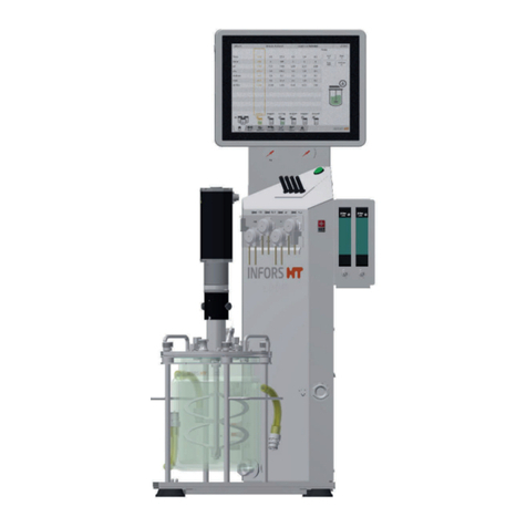
Infors HT Labfors 5 User manual
Infors HT
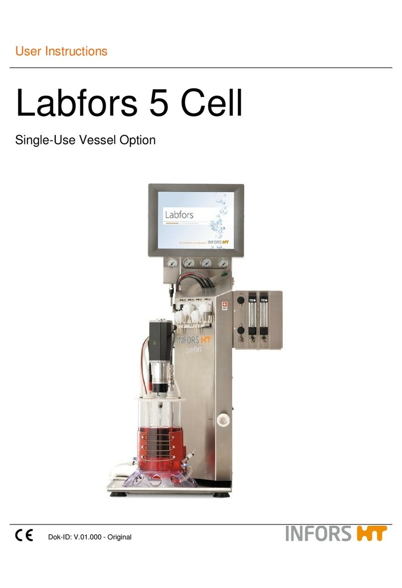
Infors HT Labfors 5 Cell User manual
Infors HT
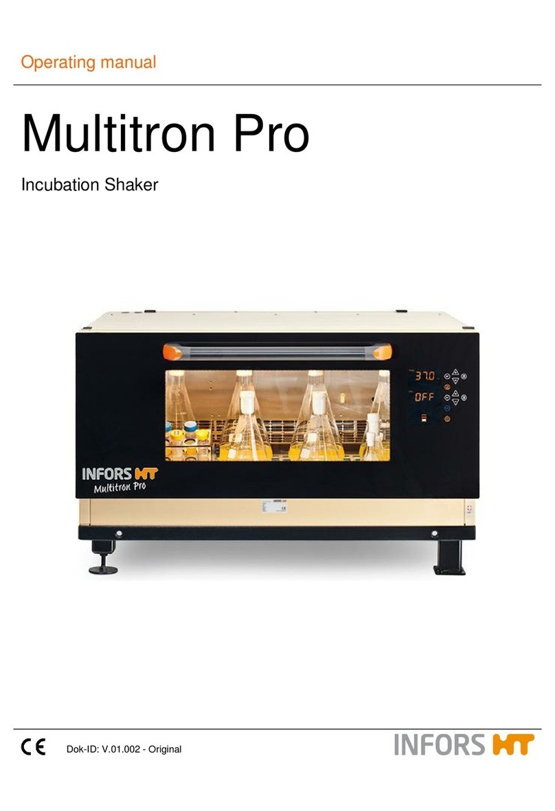
Infors HT Multitron Pro User manual

Infors HT
Infors HT Labfors 5 User manual
Infors HT
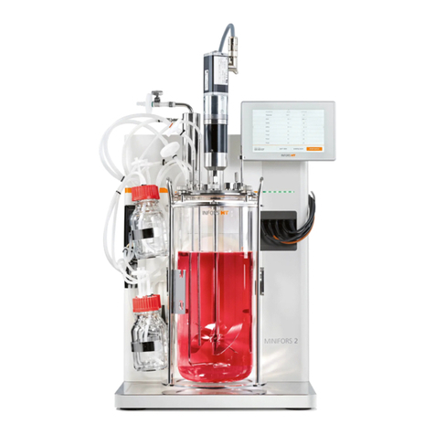
Infors HT Minifors 2 User manual
Infors HT
Infors HT Ecotron User manual

Infors HT
Infors HT Multitron User manual
Infors HT
Infors HT Multitron Standard User manual
Popular Laboratory Equipment manuals by other brands

Belden
Belden HIRSCHMANN RPI-P1-4PoE installation manual

Koehler
Koehler K1223 Series Operation and instruction manual

Globe Scientific
Globe Scientific GCM-12 quick start guide

Getinge
Getinge 86 SERIES Technical manual

CORNING
CORNING Everon 6000 user manual

Biocomp
Biocomp GRADIENT MASTER 108 operating manual


