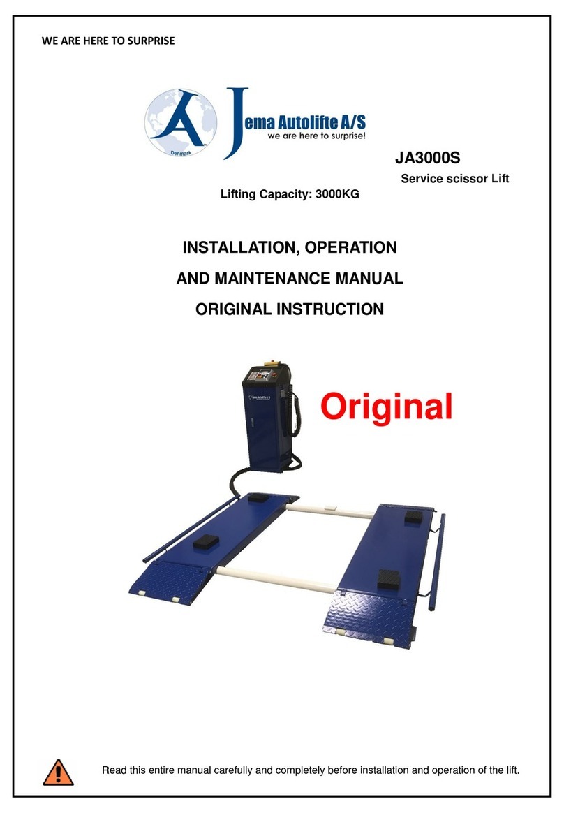
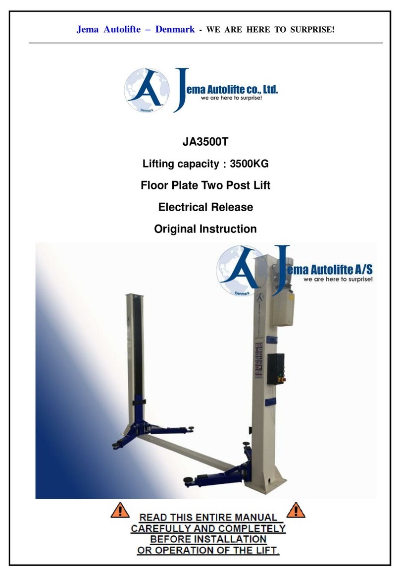
Jema Autolifte JA4200T-C Operation instructions

WE ARE HERE TO SURPRISE!
1
JA4200T-C
Lifting capacity: 4200KG
2 Post Lift
Electrical Release
Original Instruction
Read this entire manual carefully and completely before installation or operation of the lift.

WE ARE HERE TO SURPRISE!
2
INDEX
1. Important safety instructions……………………………….…3~6
1.1 Important notices
1.2 Qualified personnel
1.3 Danger notices
1.4 Condition notices
1.5 Warning signs
1.6 Level of sound pressure
1.7 Training
2. Overview of the machine………………………………………6~7
2.1 Product introduction
2.2 Technical data
2.3 Construction of the lift
3. Installation instruction…………………………………………7~13
3.1 Preparation before installation
3.1.1 Tool and equipments needed
3.1.2 Parts check
3.1.3 Floor specifications
3.2 Precautions during installation
3.3 Installation
3.4 Check list after installation
4. Operation instruction…………………………………………14~21
4.1 Precautions during operation
4.2 control box panel description
4.3 Flow chart for operation
4.4 Operation
4.5 Emergency lowing when the power is off
5. Trouble shooting………………….……………………………21~22
6. Maintenance…………………………………………………….22~23
7. Annex…………………………………………………….………23~31
Annex1. Shipping sheet
Annex2. Overall diagram
Annex3. Space required
Annex4. Hydraulic connection
Annex5. Wiring diagram
Annex6. Exploded drawing parts
Annex7. Spare parts list
Annex8. Size and weight requirement for the vehicle & valve board diagram
Annex9. CE Certificate

WE ARE HERE TO SURPRISE!
3
1. Important safety instructions
1.1 Important notices
Jema Autolifte will give the user one-year warranty of quality for the lift. If something is wrong with the lift, Jema Autolifte or the
distributor will provide the spare part for it to be replaced. Jema Autolifte will not take any responsibility for improper installation,
wrong operation, overload of the max. Lifting capacity, wrong concrete ground (that can not meet the requirements in the manual),
normal mechanical abrasion and insufficient maintenance. The warranty will be carried outon the basis of the typeand serial number
of the equipment. When contacting Jema Autolifte or the distributor the users shall provide picture documentation if asked.
The 2-post lift is suitable for lifting motor vehicles having maximum weight as described, any other use is to be considered improper
and irrational and thus highly forbidden. Jema Autolifte cannot be held responsibilities for any damage or injuries caused by an
improper use or by the non-observance of the following instructions.
Read this guide carefully before using the lift and follow the instructions given by this guide to grant the lift a correct function,
efficiency and a long service life.
1.2 Qualified personnel
1.2.1 The lift may only be used by qualified staff, properly trained for the specific use of the lift.
1.2.2 The wiring must comply with local code and a certified electrician for electrical hook up.
1.2.3 Only authorized personnel are allowed in lifting area.
1.3 Danger notices
1.3.1 Do not install the lift on any asphalt surface.
1.3.2 Read and understand all safety warning procedures before operating the lift.
1.3.3 The lift, in its standard version, is not designed for outdoor use.
1.3.4 Keep hands and feet away from any moving parts. Keep feet clear of lift when lowering.
1.3.5 The lift may only be used by qualified staff, properly trained for the specific use of the machine.
1.3.6 Do not wear unfit clothes such as large clothes with flounces, tires, etc, which could get caught by moving parts of the machine.
1.3.7 The lift surrounding area must be free from people or objects which could be a danger for lifting operations.
1.3.8 The lift is only designed to lift the entire body of vehicle, having maximum weight not more than the lift capacity.
1.3.9 Always insure the safety devices are engaged before any attempt to work on or near vehicle.
1.3.10 The vehicle must be centered and positioned in a stable correct way and following the instructions given by Jema Autolifte.
1.3.11 Make sure that the lift and its devices are working correctly, according to the specific instructions for maintenance
1.3.12 Lower the lift to its lowest position when finished.
1.3.13 Do not modify the lift without Jema Autolifte’s advice.
1.3.14 If the lift is not to be used anymore, owners is suggested to removing thepower supply connections, emptying the oil tank and
disposing the liquids by right way.
1.3.15 If the lift is to be left unused for a long period, proceed as follows:
a. Disconnect the energy source.
b. Empty the oil tank.
c. Grease the moving parts which might be damaged by dust or drying out.

WE ARE HERE TO SURPRISE!
4
1.4 Condition notices
Generally, this lift will be installed on the following conditions:
1.4.1 Supply voltage: 0.9 - 1.1 nominal supply voltage
1.4.2 Source frequency: 0.99 - 1.01 nominal frequency
1.4.3 Ambient temperature: 5? - 40?
1.4.4 Altitude: shall be at altitudes up to 1000m above mean sea level
1.4.5 Relative humidity: not exceed 50% at 40?
1.4.6 Atmosphere: Free from excessive dust, acid fume, corrosive gases and salt.
1.4.7 Avoid exposing to direct sunlight or heat rays which can change the environmental temp.
1.4.8 Avoid exposing to abnormal vibration.
1.4.9 Electrical equipment shall withstand the effects of transportation and storage temperature within a range of -25? to 55? or short
periods not exceeding 24 hours at up to +70?.
Attention: Dispose the unused oil by a correct way to protect the surround environment.
CE PLATE:

WE ARE HERE TO SURPRISE!
5
1.5 Warning signs
All safety warning signs presented on the lift with the purpose to draw the operator’s attention from dangerous or unsafe situations.
The labels must be kept clean and they have to be replaced if detached or damaged. Read the meaning of the labels

WE ARE HERE TO SURPRISE!
6
1.6 Level of sound pressure
The sound pressure of the lift does not exceed 65DB. For the sake of your healthy, we suggest you place a noise meter in the
operation area.
1.7 Training
Only qualified personnel can operate and use the lift. Contact Jema Autolifte or the distributor to provide with trained courses and aid
you in becoming familiar with the lift.
2. Overview of the machine
2.1 Product Introduction
The floor plate lift is composed of posts, carriages, lifting arms, hydraulic cylinders, power unit and floor plate, etc. The lift is operated
by an electric motor controlling a hydraulic system, which delivers the hydraulic fluid to cylinders inside the columns for lifting two
carriages. The safety teeth block will bite with safety plate in the posts automatically. Therefore, the lift will not lower when hydraulic
system trouble happens.
Safety structure:
Safety lock

WE ARE HERE TO SURPRISE!
7
2.2 Technical data
2.3 Construction of the lift
3. Installation instruction
3.1 Preparation before installation
3.1.1 Tools and equipments needed
Appropriate lifting equipment
AW 32. 46 or other good quality garage hydraulic oil.
Rotary Hammer Drill with 3/4’’ drill bit.
Chalk line and tape measure.
Sockets and Open wrench set.
Hammer 4pounds
Ф2 tape measure
Model
Lifting
capacity
Lifting
time
Lifting
height
Height
Width
Width
between
posts
Voltage
Max
pressure
Gross
weight
JA4200T-C
4200kg
50 Sec
1900mm
2910mm
3545mm
2835mm
380v
26MPa
600kg

WE ARE HERE TO SURPRISE!
8
3.1.2 Parts check --- Annex 1(shipping sheet)
Remove the packaging and check that all parts for the lift are in the package per. Annex 1. Please contact Jema Autolifte or the
distributor where the purchase is undertaken if any parts are missing. If you do not contact Jema Autolifte or the distributor within 2
weeks of receipt, and missing parts are noticed when installing the lift, will Jema Autolifte as well as our distributors not be
responsible for missing parts and will charge for the purchase of spare parts.
3.1.3 Floor specifications
The lift should be fixed on a smooth and solid concrete ground with its strength more than 3000psi, tolerance of flatness less
than 5mm and minimum thickness of 200mm. In addition, newly built concrete ground must undergo more than 28days’ cure
and reinforcement.
3.2 Precautions during installation
3.2.1 Make sure that the columns are vertical to the floor.
3.2.2 When installing the hydraulic oil hoses on both piston and engine please make sure they are installed properly to
prevent oil leaks.
3.2.3 All bolts on the lift must be tightened when the lift is assembled as they may have shaken themselves loose during
transport.
3.2.4 Placing no vehicle on the lift before it is tested after installation.
3.3 Installation
Step 1: Remove the packing of the lift and remove the cardboard box with accessories, and the floor plate.
Step 2: Remove the lift arms and the control box located the columns
Step 3: Support the columns and remove the bolts that hold the columns in each end of the transport cage.
NOTE: Be careful if the columns falls down will the lift or people around the lift be injury
Step 4: Rise the columns in vertical position with a lifting device lifting.

WE ARE HERE TO SURPRISE!
9
Step 5: Decide the installation position of the columns, erect the main and assistant post. Pay attention that the
width between posts is 2830mm.
1. It must also be decided on which side the main column should be placed. (Normally left in the access direction is normal)
2. When the position is selected, use now lime ribbon to place the main column and the assisting column in line to each other.
3. Before work is continued, double check that the columns are the correct position in the room and the columns are properly placed
to each other.
Step 6: Rise the columns, main post first and then the assistant post
Before drilling holes for fixing the columns, place the complete floor plate in between the columns in order to
ensure that the distance is correct.
Floor plate

WE ARE HERE TO SURPRISE!
10
1、Drill each anchor hole in the concrete using a rotary hammer drill. To assure full holding power, do not
ream the hole or allow drill to wobble
2、After drilling, remove dust thoroughly from each hole and make certain that the column remains aligned
with the chalk line during this process.
3、Position the main column at the designated chalk locations and follow the same procedures step 1, 2 to position the assistant
column.
Step 7: Installation and adjustment of the calibration wire
1. Rise and lock each carriage approximately 800 mm bottom position.
2. Make sure the safety locks in each column is activated before mounting the calibration wires.
3. Both carriages for the main column and the Assistant column must be the same height when installing the calibration wires.
4. With the carriages at the same height from the floor, install the calibration wires as shown below.
5. After the calibration wires are installed, each wire adjusted to have a uniform stance.
(It is IMPORTANT the calibration wires are not to tight since that will give unexpected load on the wire wheel and bushings)
6. Lubricate the wire with Chain spray or grease.
Step 8: Install the power unit on the main column.
1. Install the power unit with the 8mm bolts which is with the lift.
(The bolts should NOT be tightend before the hydraulic oil hoses and been installed)
The bolt and nut to adjust the
calibration wire
8mm bolte

WE ARE HERE TO SURPRISE!
11
Step 9: Install the hydraulic oil hoses on the main column.
Step 10: Install four safety plates, four electromagnets and the electromagnet covers. Connect the wire to
electromagnets.
Safety plate
Electromagnet
Cover

WE ARE HERE TO SURPRISE!
12
Step 11: Mount the control box (Remember to fasten all terminal blocks and wires as they may shake loose during transport)
1. Connect the power unit with the control box as the wiring diagram
2. Connect the limit switch on the main Column. (NB. Note the misalignment of the limited switch within the column!)
Step 12: Install the oil hose cover of the both columns.
Step 13: Install the lifting arms
Mount the lift arms with the supplied mandrels, it is important respect of the weight distribution on the lift that the long arms are
ALWAYS placed at the rear of the vehicle and therefore will be mounted as shown on the picture below. Check and adjust the arm
lock to go in the grip when the lift is raised so that the arms cannot move away under the vehicle when lifting.
Limit switch
Entry direction
Long arm
Long arm
Short arm
Short arm

WE ARE HERE TO SURPRISE!
13
Step 14: Add the hydraulic oil
The volume of the oil tank is 12L
,
To insure the lift in a normal work condition, the oil should be over 90% of the oil tank volume;
Use AW 32# in winter/46# in summer or other good quality garage hydraulic oil.
Step 15: When all the steps from 1 to 14 are double-checked, connect the lift to power and try to press the "UP"
button (Do not place any vehicle in this step)
Step 16: Install the chain protection and the door-opening protection
Trin 17: Install the Cover plate on the floor plate.
When everything has been installed and the lift is tested, then install the foot protection, plastic tops and high adaptors.
Chain protection
Door-opening protection

WE ARE HERE TO SURPRISE!
14
3.4 Check list after installation
TIGHHTENED EVERYTHING AGAIN WHEN LIFT HAS BEEN USED FOR 2-3 DAYS
4. Operation instruction
4.1 Precautions during operation
Remark: Only authorized staff can adjust the system pressure on the power unit.
4.1.1 Check all the hydraulic oil hoses and connections before use. The lift can only be used if there are no leakages.
4.1.2 The lift should not be used if the safety devices fails or do not perform the required safety function.
4.1.3 The lift shall not rise or lower any vehicle if the center of gravity of the vehicle is not within the supporting range of
the regulation show within the manual. Otherwise, Jema Autolifte or the distributor will not bear any responsibility for the
consequence resulted from the wrong operation.
4.1.4 The staff or operators shall be in a safe position when the lift rise or lower.
4.1.5 When the lift with vehicle reaches a desired height, ALWAYS lower the lift to the safety locks, and main switch must be
turned off before the vehicle is repaired so as to prevent non-operator or unauthorized person from pressing any button which
can jeopardize the safety of anyone around or under the vehicle.
4.1.6 REMEMBER never work at or under the vehicle without the lift is set in safety lock. Never allow anyone stepping in under or
nearby the lift when raised or lowering.
S/N
Check items
YES
NO
1
Are the columns placed 100% vertically?
2
Are columns placed opposite each other?
3
Are all hydraulic hoses tight?
4
Are ALL cables in the control box tightened?
5
Are ALL screws and bolts on the lift tightened?
6
Are the arm locks properly adjusted so they go in grip when lifting?
7
Are the lift safely and securely anchored in the floor?

WE ARE HERE TO SURPRISE!
15
4.2 Control box panel description
4.3 Flow chart for operation
Lowering
Start
Press DOWN button
Turn on the power switch
Rising
Start
Turn on the power switch
Press UP button
The lift will start to rise
When the lift reaches the desired
height press the "SAFETY LOCK and the
lift goes into safety lock
The lift is lowered
The work can be
started
Power lamp: show the power is on
Up button: raise the lift
Safety button: make sure the security during the repair work
Down button: lower the lift
Main switch: connect the power
Emergent stop: ensure safety

WE ARE HERE TO SURPRISE!
16
4.4 Operation
Adjust the lift -> The lift is calibrated by the calibration wires -> If the lift is not rise up equally on both carriages, the
adjust the calibration wires.
The lift should be raised and lowered 3 to 4 times and then the hydraulic system has been vented
Raise the lift
1、Place the vehicle parallel between the columns.
2、Turn the lift arms under the vehicle and place lifting platforms under the lifting points on the vehicle. Make sure that the vehicle's
center of gravity is placed acc. The provisions of the manual
3、Turn on the power switch, so the light turns on and power is being supplied to the lift. Press "UP" button until the lift platforms is
touch the lifting points on the vehicle, check out again if lifting platforms are perfect and firmly placed on the lifting points on the
vehicle and it is reasonable to continue to lift the vehicle.
4、Push the “UP” Button when the vehicle has reached the desired height.
5、Push the “Safety lock” Button so the lift lowers to the nearest safety lock.
6、Check again that the vehicle is safely placed on the lifting platforms.
7, If the vehicle is not placed safely then please lower the vehicle and start again from no. 2!
8, If the vehicle is placed correct and safe on the lifting platforms, turn off the power switch and the work on the vehicle can start.
Lower the lift
1. Turn on the power switch.
2. Push the “DOWN” button, the lift will start to rise up the amount of seconds the lift has been adjusted to. Here after will
the safety locks release and the lift will start to lower the vehicle until the lift is all the way down.
3. If more work must be carried out in a lower position, then the user must remember to press the "SAFETY LOCK"
Button when the desired height is reached and turn off the power switch.
4. Turn off the power switch.
5. Pull out the lifting arms away under the vehicle and check whether any possibly tools or other objects around the
vehicle.
6. Remove the vehicle from the lift
Note: It is important that the power is switched off when the lift is not in use!

WE ARE HERE TO SURPRISE!
17
4.5 Emergency lowering when the power is off
The carriage is NOT engaged:
a. Pull off the electromagnets on the both posts
b. Loosen the electrical valve of the power unit to lower the carriage
The carriage IS engaged:
a. Screw off the fitting (opposite of the oil out-let) to connect the manual hydraulic pump. Press the handle of the Manual hydraulic
pump (Manual hydraulic pump is optional) to supply oil to the cylinder to release the lock
Electromagnet

WE ARE HERE TO SURPRISE!
18
C .Pull off the electromagnets on the both posts.
d. Loose the electrical valve of the power unit to lower the carriage.
Electromagnet

WE ARE HERE TO SURPRISE!
19
5. Trouble Shooting
ATTENTION: If you could not do the trouble shooting by your own, please contact Jema Autolifte or the distributor for
help. You are requested to send us the series No. with detailed description of faulty of the lift or parts. We keep the right
to ask for photos and pictures for diagnostics
.
TROUBLE
CAUSE
SOLUTION
Murmurs from the lift
Check if the chain is placed correct
Adjust or change the chain
Check the conduits are corrected mounted
Adjust or change the conduits
Check if there are dirt in the column
Clean and grease the column
Motor does not run and
lift will not rise
Check electric wires
Tighten all electric connections
Motor is burned off
Change the motor
The high limited switch is broken or has a
loose wires connection
Change the high limited switch or connect the
electric wires correct
Motor runs but the lift does
not rise
The Motor turn the wrong way around
Check the 380V connection.
There are dirt in the valves
Clean all the valves on the pump
The gear pump is broken
Change the gear pump
The lift is missing hydraulic oil
When the lift is lowered should the oil tank
be ¾ full. (12L)
The suction pipe in the tank is loose
Tighten the suction pipe
There is dirt in the oil filter in the oil tank
Clean or change the oil filter and hydraulic oil
Motor runs but will not
raise
The hydraulic oil hoses are not correct
installed
Check whether the hydraulic hoses are
properly acc. Assembly instructions
The lift is rising and
lowering very slow
The pump pressure is not adjust correct
Adjust the pump pressure as instructed
The Hydraulic piston is leaking oil
Change the seal or the piston
There is dirt in the lowering valve
Clean or change the lowering valve
The overflow valve is leaking oil
Change the overflow valve
The top screw is the main piston is loose
Tighten the screw or change the piston
There is dirt in the oil filter in the oil tank
Clean or change the oil filter and hydraulic oil
The lift may not be used!
The hydraulic oil is dirty
Change or order service check
The temperature is too high/low
Max./min. Temp. 5° til 40°
40°
40°
The safety devices do not work
Change the parts or order service check

WE ARE HERE TO SURPRISE!
20
6. Maintenance
Maintaining the lift is incredibly important to make sure the lift is safe to work with and the lift span is extended.
If the lift is not being maintained according to the requirements by a professional technical company will Jema Autolifte
not be responsible for any accidents or errors that might occur with the lift.
THE FOLLOWING PARTS ARE NEEDED TO BE LUBRICATED.
IMPORTANT: Check the lifting platforms are in perfect condition before using the lift!
6.1. DAILY PRE-OPERATION CHECK
The user should perform daily check. Daily check of safety latch system is very important –the discovery of device failure
before needed could save you from expensive property damage, lost production time, serious personal injury, even death.
Check safety lock audibly and visually while in operation.
Check safety latch for free movement and full engagement with rack.
Check hydraulic connections and hoses for leakage.
Check chain connections for bends, cracks and looseness.
Check cables connections for bends, cracks and looseness.
Check for frayed cables in both raised and lowered position.
Check snap rings at each roller and sheave.
Check bolts, nut and screws. Tighten if needed.
Check wiring and switches for damage.
Keep base plate free of dirt, grease or any other corrosive substances.
Check floor for stress cracks near anchor bolts.
S/N
Description
1
Top wire wheel
2
Wire rope
3
Chain wheel
4
Chain
5
Sliding block
6
Pin
7
Arm block
8
Lifting arm
9
Tray
10
Buttom wire wheel
Table of contents
Other Jema Autolifte Lifting System manuals