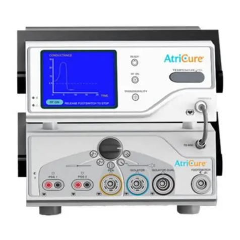
ArtiCure ASU2 User manual

2023/02 | IFU-0435.A
EN
MD
Ablation and Sensing Unit and
AtriCure Switch Matrix RF Generator System
Instructions for Use
ASU2 and ASB3
AtriCure Inc.
7555 Innovation Way
Mason, Ohio 45040
USA
+1 866 349 2342
+1 513 755 4100

22023/02 | IFU-0435.A
TABLE OF CONTENTS
DEVICE DESCRIPTION������������������������������������������������������������������������������������������������������������������������������������������������� 4
INTENDED PURPOSE ��������������������������������������������������������������������������������������������������������������������������������������������������������������������������������������������������������������������������� 4
INDICATIONS FOR USE������������������������������������������������������������������������������������������������������������������������������������������������������������������������������������������������������������������������ 4
INTENDED USER ����������������������������������������������������������������������������������������������������������������������������������������������������������������������������������������������������������������������������������� 4
TARGET PATIENT POPULATION ��������������������������������������������������������������������������������������������������������������������������������������������������������������������������������������������������������� 4
CLINICAL BENEFIT�������������������������������������������������������������������������������������������������������������������������������������������������������������������������������������������������������������������������������� 4
SERIOUS INCIDENT STATEMENT ������������������������������������������������������������������������������������������������������������������������������������������������������������������������������������������������������� 4
NON-STERILE����������������������������������������������������������������������������������������������������������������������������������������������������������������������������������������������������������������������������������������� 4
CAUTIONS ������������������������������������������������������������������������������������������������������������������������������������������������������������������������������������������������������������������������������������ 5
CLASSIFICATION IN ACCORDANCE WITH EN 60601-1 SAFETY INFORMATION 6
EMC GUIDANCE AND MANUFACTURER’S DECLARATION 6
ELECTROMAGNETIC REQUIREMENTS���������������������������������������������������������������������������������������������������������������������������������������������������������������������������������������������� 6
ESSENTIAL PERFORMANCE���������������������������������������������������������������������������������������������������������������������������������������������������������������������������������������������������������������� 6
ELECTROMAGNETIC EMISSIONS������������������������������������������������������������������������������������������������������������������������������������������������������������������������������������������������������� 6
ELECTROMAGNETIC IMMUNITY ������������������������������������������������������������������������������������������������������������������������������������������������������������������������������������������������������� 7
EMC GUIDANCE AND MANUFACTURER’S DECLARATION 8
RECOMMENDED SEPARATION DISTANCE��������������������������������������������������������������������������������������������������������������������������������������������������������������������������������������� 9
GLOSSARY OF TERMS�������������������������������������������������������������������������������������������������������������������������������������������������������������������������������������������������������������������������� 9
SYMBOLS GLOSSARY�������������������������������������������������������������������������������������������������������������������������������������������������������������������������������������������������������������������������10
CHAPTER 1 INSTRUCTIONS FOR USE������������������������������������������������������������������������������������������������������������������������ 11
SYSTEM OPERATING MODES�����������������������������������������������������������������������������������������������������������������������������������������������������������������������������������������������������������12
POWER AND VOLTAGE OUTPUT DIAGRAMS��������������������������������������������������������������������������������������������������������������������������������������������������������������������������������12
SYSTEM OVERVIEW����������������������������������������������������������������������������������������������������������������������������������������������������������������������������������������������������������������������������13
COMPONENTS NOT SUPPLIED WITH THE ASU/ASB SYSTEM 14
ASU/ASB SYSTEM USER INTERFACE�����������������������������������������������������������������������������������������������������������������������������������������������������������������������������������������������14
FRONT AND BACK PANEL CONNECTORS/CONTROLS 15
CHAPTER 2 SETUP AND OPERATION ������������������������������������������������������������������������������������������������������������������������ 17
SETTING UP THE DEVICE ������������������������������������������������������������������������������������������������������������������������������������������������������������������������������������������������������������������17
DEVICE OPERATION���������������������������������������������������������������������������������������������������������������������������������������������������������������������������������������������������������������������������19
CHAPTER 3 PREVENTIVE MAINTENANCE AND CLEANING 20
CLEANING GUIDELINES ��������������������������������������������������������������������������������������������������������������������������������������������������������������������������������������������������������������������20
PREVENTIVE MAINTENANCE PROGRAM���������������������������������������������������������������������������������������������������������������������������������������������������������������������������������������20
PERIODIC INSPECTIONS��������������������������������������������������������������������������������������������������������������������������������������������������������������������������������������������������������������������20
VISUAL INSPECTION ��������������������������������������������������������������������������������������������������������������������������������������������������������������������������������������������������������������������������20
OPERATING TEST��������������������������������������������������������������������������������������������������������������������������������������������������������������������������������������������������������������������������������20
CHAPTER 4 TECHNICAL SPECIFICATIONS AND SAFETY INSPECTION 21
MECHANICAL SPECIFICATIONS�������������������������������������������������������������������������������������������������������������������������������������������������������������������������������������������������������21
TECHNICAL SPECIFICATIONS�����������������������������������������������������������������������������������������������������������������������������������������������������������������������������������������������������������21
RF OUTPUT ������������������������������������������������������������������������������������������������������������������������������������������������������������������������������������������������������������������������������������������21
ELECTRICAL SPECIFICATIONS����������������������������������������������������������������������������������������������������������������������������������������������������������������������������������������������������������21
ENVIRONMENTAL SPECIFICATIONS �����������������������������������������������������������������������������������������������������������������������������������������������������������������������������������������������21

32023/02 | IFU-0435.A
EQUIPMENT TYPE/CLASSIFICATION ����������������������������������������������������������������������������������������������������������������������������������������������������������������������������������� 21
FOOTSWITCH SPECIFICATIONS �������������������������������������������������������������������������������������������������������������������������������������������������������������������������������������������� 21
FUSE SPECIFICATIONS������������������������������������������������������������������������������������������������������������������������������������������������������������������������������������������������������������ 21
EXPECTED LIFETIME ��������������������������������������������������������������������������������������������������������������������������������������������������������������������������������������������������������������� 21
CHAPTER 5 TROUBLESHOOTING�����������������������������������������������������������������������������������������������������������������������21
NO RF POWER OUTPUT ��������������������������������������������������������������������������������������������������������������������������������������������������������������������������������������������������������� 22
ERROR CODES�������������������������������������������������������������������������������������������������������������������������������������������������������������������������������������������������������������������������� 22
MONITOR (DISPLAY) INTERFERENCE���������������������������������������������������������������������������������������������������������������������������������������������������������������������������������� 23
CONTINUOUS INTERFERENCE���������������������������������������������������������������������������������������������������������������������������������������������������������������������������������������������� 23
INTERFERENCE ONLY WHEN ASU/ASB IS ACTIVATED 23
NEUROMUSCULAR STIMULATION �������������������������������������������������������������������������������������������������������������������������������������������������������������������������������������� 23
PACEMAKER INTERFERENCE������������������������������������������������������������������������������������������������������������������������������������������������������������������������������������������������� 23
CHAPTER 6 CUSTOMER SERVICE/EQUIPMENT SERVICING/WARRANTY 23
DISCLAIMER ������������������������������������������������������������������������������������������������������������������������������������������������������24

42023/02 | IFU-0435.A
DEVICE DESCRIPTION
The AtriCure® Ablation and Sensing Unit Radiofrequency (RF)
Generator produces and delivers RF energy, in a bipolar mode, at
a frequency of approximately 460 kHz, for localized tissue heating
resulting in tissue coagulation�
The AtriCure Switch Matrix provides a means of simultaneously
connecting multiple AtriCure Bipolar handpieces to the AtriCure
Ablation and Sensing Unit and the means to select the input to the
handpiece electrodes using the Switch Matrix knob�
This Instructions for Use (IFU) applies to the Ablation and Sensing Unit
(ASU)-AtriCure Switch Matrix (ASB) system� For the user’s convenience:
• The AtriCure Ablaon and Sensing Unit RF Generator will
be referred to in this IFU as ASU, and
• The AtriCure Switch Matrix will be referred to in this IFU as
ASB when referencing the generator controls.
• The AtriCure Bipolar Handpiece will be referred to in this
IFU as the Handpiece.
• The ASU/ASB system may also be referred to as the Device
or Generator.
The ASU provides a maximum output power ranging from
12.0 Was (W) up to 30.0 W for the Isolator®TranspolarTM pen
or CoolRailTM linear pen devices depending on the mode of
operaon, and 22.8 W up to 28.5 W for the Isolator SynergyTM
clamps or Isolator Synergy Access® clamps when used with the
ASB. The ASU can produce a maximum output power of 32.5
W under a 100 Ohm load, although no current AtriCure Bipolar
Handpiece uses Power above 30 Was (W).
The operating mode is a function of the Handpiece and is set by the
ASU/ASB system� The ASU/ASB system is designed to operate only
with AtriCure Bipolar Handpieces (AtriCure Isolator pens, or AtriCure
CoolRaillinear pen and Isolator Synergy Clamps)� The Footswitch is the
input device used to activate and deactivate the RF energy delivery�
Please refer to the Handpiece IFU for a complete description of the
indications and use of these devices�
This IFU describes the ASU/ASB system, its controls, displays,
indicators, tones, and a sequence for its operation with AtriCure
Handpiece(s) only� This IFU also supplies other information of
importance to the user and is not a reference to surgical techniques�
The AtriCure ASU/ASB and its components are intended to be used in
professional healthcare environment only�
INTENDED PURPOSE
The ASU Generator/ASB Switch Matrix system is a non-sterile, reusable
medical device intended to transmit radiofrequency (RF) energy to
compatible AtriCure ablation handpieces for ablation of cardiac tissue�
INDICATIONS FOR USE
The ASU Generator/ASB Switch Matrix system is indicated to
transmit radiofrequency (RF) energy to compatible AtriCure ablation
handpieces for treatment of arrhythmias including atrial brillation�
INTENDED USER
Licensed medical doctors who perform cardiac and/or thoracic
surgical procedures using AtriCure instrumentation�
TARGET PATIENT POPULATION
Adult patients with arrhythmias including atrial brillation�
CLINICAL BENEFIT
To achieve the clinical benet of compatible AtriCure ablation
handpieces�
SERIOUS INCIDENT STATEMENT
Any serious incident that has occurred in relation to this device should
be reported to AtriCure and the competent authority of the Member
State in which the user and/or patient is located�
NON-STERILE
• The ASU/ASB system is provided non-sterile and not intended for
use within the sterile eld� Do not sterilize the ASU/ASB system
with any sterilization method, or the ASU/ASB system may be
damaged� Follow cleaning instructions in CHAPTER 3 PREVENTIVE
MAINTENANCE AND CLEANING to clean the system and the
compatible reusable components�
WARNINGS
• Do not operate the ASU/ASB before thoroughly reading this ifu�
• Do not use the ASU/ASB in the presence of ammable
anesthetics, other ammable gases, ammable cleaning agents,
near ammable uids such as skin prepping agents and tinctures,
ammable objects, or with oxidizing agents� Use near ammable
agents may result in re or explosion� Observe appropriate re
precautions at all times�
• Fire Hazard: Electrosurgical accessories that are activated or hot
from use can cause a re� Do not place them near or in contact
with ammable materials (such as gauze or surgical drapes)�
Avoid igniting endogenous gases�
• Fire Hazard: To avoid igniting cleaning agents, use only non-
ammable agents to clean and disinfect the ASU/ASB� If
ammable agents are inadvertently used on the Generator, allow
these substances to evaporate completely before operating�
• Electrosurgery should be used with caution in the presence of
internal or external pacemakers� Interference produced with
the use of electrosurgical devices can cause devices such as a
pacemaker to enter an asynchronous mode or can block the
pacemaker entirely� Consult the pacemaker manufacturer or
hospital Cardiology department for further information when
the use of electrosurgical appliances is planned in patients with
cardiac pacemakers�
• The use of components, transducers, and cables other than
those specied in accordance with the instructions or supplied
by AtriCure, may result in increased emissions or decreased
immunity of the equipment�

52023/02 | IFU-0435.A
• The ASU/ASB should not be used adjacent or stacked with
other equipment, except for intended stacking with AtriCure’s
equipment in accordance with the instructions� The ASU/ASB
normal use conguration should be observed to verify normal
operation�
• The voltage selector is factory set and should not be changed by
the user� The voltage selector and the power entry module must
be set to the same voltage setting to prevent ASU malfunction and
potential instrument damage�
• The Power cord(s) of the ASU/ASB must be connected to a properly
grounded receptacle(s)� Extension cords and/or adapter plugs
must not be used�
• Electric Shock Hazard: Do not connect wet components to the
Generator�
• Electric Shock Hazard: Ensure that the Handpiece is correctly
connected to the Generator and that no wires are exposed from
the cable, connector, or Handpiece�
• Do not connect the ASU/ASB device cable to supply mains (line
voltage) operated equipment without evidence that the safety
certication of the Accessory has been performed in accordance
to the appropriate EN60601-1 and/or EN60601-1-1 harmonized
national standard� Supply mains operated equipment may
introduce dangerous leakage currents into the heart� When
transporting or handling the ASU/ASB, use caution and care
to avoid product damage� Inspect the ASU/ASB and Interface
cables for any signs of physical damage before use� If damage is
found, the integrity of the product cannot be guaranteed, and the
product should not be used�
• Make sure there are no obstructions underneath or near the rear of
the ASU/ASB to provide sucient air ow for cooling�
• Use care when connecting Footswitch, Power cords, or Handpieces�
Failure to connect properly may result in product damage�
• The safe and eective use of RF energy is highly dependent upon
factors under the control of the operator� The manual, and the
equipment it describes, are for use only by qualied medical
professionals trained in the particular technique and surgical
procedure to be performed� It is important that the operating
instructions supplied with the ASU/ASB be read, understood and
followed before use to avoid product damage or patient harm�
• If the ASU powers down, use CHAPTER 5 TROUBLESHOOTING to
attempt to correct the problem� If problem persists, contact the
AtriCure representative�
• The activation tone and indicator are important safety features�
Do not obstruct the activation indicator or disable the audible
tone� Ensure that the activation tone is audible to personnel in
the Operating Room (OR) prior to use� The activation tone alerts
personnel when the Handpiece is active and can help avoid tissue
damage�
• Follow the cleaning instructions detailed in CHAPTER 3
PREVENTIVE MAINTENANCE AND CLEANING� Failure to follow these
guidelines may result in product damage�
• Portable RF communications equipment (including peripherals
such as antenna cables and external antennas) should be used no
closer than 30 cm (12 inches) to any part of the ASU/ASB including
cables specied by the manufacturer� Otherwise, degradation of
the performance of this equipment could result�
CAUTIONS
• Use only with the AtriCure Handpieces intended for use with the
ASU/ASB�
• Do not activate the Generator until the Handpiece is properly
positioned in the patient�
• Electric shock hazard: Do not remove the cover of the ASU/ASB as
there is a potential for electric shock� Refer to authorized personnel
for service�
• Trip Hazard: Standard care should be used to reduce the risk of
tripping on the Footswitch cable�
• Use only the Footswitch provided with the ASU/ASB�
• Do not wrap instrument cables around metal objects� Wrapping
cables around metal objects may induce hazardous currents�
• To avoid shock, do not allow patients to come into contact with
earth metal parts of the Device� The use of antistatic sheeting is
recommended�
• When the ASU/ASB is activated, the conducted and radiated
electrical elds may interfere with other electrical medical
equipment� Refer to the EMC Guidance and Manufacturer’s
Declaration section for more information regarding potential
electromagnetic or other interference and advice regarding
avoidance of such interference�
• Studies have shown that smoke generated during electrosurgical
procedures can be potentially harmful to surgical personnel�
These studies recommend using surgical masks and adequately
ventilating the smoke by using a smoke evacuator or other means�
• When the Generator and Handpiece are used on a patient
simultaneously with physiological monitoring equipment, ensure
that the monitoring electrodes are placed as far as possible from
the surgical electrodes� Be sure to position the Handpiece cables
so that they do not come in contact with the patient or the other
leads�
• Needle monitoring electrodes are not recommended for use when
operating the Generator and the Handpiece�
• Monitoring systems that incorporate high-frequency current-
limiting devices are recommended for use with the Generator and
the Handpiece�
• Failure of the Device and the Handpiece could result in unintended
Power output increases�
• Handle the ASU and ASB packaging with care�
• The ASU/ASB, AtriCure Isolator Transpolar Pen, Coolrail Linear Pens,
Isolator Synergy Clamps have been tested as a system� Another
manufacturer’s accessories are not compatible and will not
connect to the ASU/ASB�
• The ASU/ASB generates, uses, and can radiate RF energy�
Interference produced by the operation of the ASU/ASB may
adversely inuence the operation of other electronic medical
equipment such as monitors and imaging systems�

62023/02 | IFU-0435.A
CLASSIFICATION IN ACCORDANCE WITH EN 60601-1 SAFETY INFORMATION
Radiofrequency Ablation Device:
ASU, rated: 100-120V ~ 50/60 Hz
ASB, rated: 100-240V ~ 50/60 Hz
1� Type of protection against electric shock: Class 1
2� Degree of protection against electric shock: Type CF
3� Degree of protection against ingress of water: N/A
4� Equipment not suitable for use in the presence of ammable anesthetic mixture with air or with oxygen or nitrous oxide
5� Mode of operation: Intermittent
EMC GUIDANCE AND MANUFACTURER’S DECLARATION
ELECTROMAGNETIC REQUIREMENTS
The ASU/ASB system has been tested and found to comply with the limits for medical devices in EN 60601-1-2:2015 + A1:2021 These limits are
designed to provide reasonable protection against harmful interference in a typical medical installation� This system generates, uses, and can
radiate RF energy and, if not installed and used in accordance with the instruction given below, may cause harmful interference to other devices
in the vicinity� However, there is no guarantee that interference will not occur in a particular installation� The ASU/ASB do not require preventive
maintenance with regard to electromagnetic disturbance during the expected service life� If the ASU/ASB does cause harmful interference to
other devices, which can be determined by turning the ASU/ASB OFF and ON, the operator is encouraged to try to correct the interference by:
• Relocate or reorient the equipment
• Increase the separation distance between the equipment and the other devices
• Connect the equipment into other outlets dierent from those to which the other devices are connected
• Consult AtriCure, Inc� representatives for help�
ESSENTIAL PERFORMANCE
The Generator shall not deliver excess energy to the patient�
ELECTROMAGNETIC EMISSIONS
Table A: IEC EMC Specications (Emissions)
Guidance and Manufacturer’s Declaration – Electromagnetic Emissions
The ASU/ASB is intended for use in the electromagnetic environment specied below. The customer or the user of the ASU/ASB System should assure that it is used in such an
environment.
Emissions Test Compliance Electromagnetic Environment – Guidance
Radiated RF emissions
CISPR 11
Group 1 Class A The ASU/ASB must emit electromagnetic energy in order to perform its intended function. Nearby electronic
equipment may be aected.
Conducted RF emissions
CISPR 11
Group 1 Class A The ASU/ASB is suitable for use in all establishments other than domestic and those directly connected to the public
low-voltage power supply network that supplies buildings used for domestic purposes.
Harmonics emissions
IEC 61000-3-2
Class A
Voltage changes /
uctuations / icker
IEC 61000-3-3
Complies
NOTE:The emissions characteristics of this equipment make it suitable for use in industrial areas and hospitals (CISPR 11 Class A). If it is used in a residential environment (for which
CISPR 11 Class B is normally required), this equipment might not oer adequate protection to radiofrequency communication services. The user might need to take mitigation
measures, such as relocating or re-orienting the equipment.

72023/02 | IFU-0435.A
ELECTROMAGNETIC IMMUNITY
Table B: IEC EMC Specications (Immunity)
Guidance and Manufacturer’s Declaration – Electromagnetic Immunity
The ASU/ASB is intended for use in the electromagnetic environment specied below. The customer or the user of the ASU/ASB System should assure that it is used in such an
environment.
Immunity test IEC 60601 test level Compliance level Electromagnetic environment -
Guidance
Electrostatic discharge (ESD)
IEC 61000-4-2
± 8 kV contact
± 2 kV, ± 4 kV, ± 8 kV,
± 15 kV air
± 8 kV contact
± 2 kV, ± 4 kV, ± 8 kV,
± 15 kV air
Floors should be wood, concrete, or ceramic
tile. If oors are covered with synthetic
material, the relative humidity should be at
least 30%.
Electrical fast transient/ burst
IEC 61000-4-4
± 2 kV @ 100 kHz repetition frequency
for power supply lines
± 2 kV @ 100 kHz repetition frequency
for input/output lines
± 2 kV @ 100 kHz repetition frequency
for power supply lines
± 2 kV @ 100 kHz repetition frequency
for input/ output lines
Mains power quality should be that of a
typical commercial or hospital environment.
Surge
IEC 61000-4-5
Power inputs
± 0,5 kV, ± 1 kV Line-to-Line
± 0,5 kV, ± 1 kV, ± 2 kV Line-to-Ground
Signal input/outputs:
± 2 kV Line-to-Ground
Power inputs
± 0,5 kV, ± 1 kV Line-to-Line
± 0,5 kV, ± 1 kV, ± 2 kV Line-to-Ground
Signal input/outputs:
± 2 kV Line-to-Ground
Mains power quality should be that of a
typical commercial or hospital environment.
Voltage dips, short interruptions, and
voltage variations on power supply input
lines
IEC 61000-4-11
Voltage Dips:
0 % UT; 0,5 cycle
At 0°, 45°, 90°, 135°, 180°, 225°, 270°
and 315° phase angles
0 % UT; 1 cycle and
70 % UT; 25/30 cycles
Single phase: at 0°
Voltage interruptions:
0 % UT; 250/300 cycle
Voltage Dips:
0 % UT; 0,5 cycle
At 0°, 45°, 90°, 135°, 180°, 225°, 270°
and 315° phase angles
0 % UT; 1 cycle
Single phase: at 0°
70 % UT; 25/30 cycles
Single phase: at 0°
Voltage interruptions:
0 % UT; 250/300 cycle
Mains power quality should be that of a
typical commercial or hospital environment.
If the user of the ASU System requires
continued operation during power mains
interruptions, it is recommended that
the ASU System be powered from an
uninterruptible power supply or battery
Power frequency (50/60 Hz) magnetic
eld
IEC 61000-4-8
30 A/m
50 Hz or 60 Hz
30 A/m
50 Hz or 60 Hz
Power frequency magnetic elds should be
at levels characteristic of typical location in a
typical commercial or hospital environment.
Conducted RF
IEC 61000-4-6
0,15 MHz – 80 MHz
3V, 80 % AM at 1 kHz
ISM bands between 0,15 MHz and 80
MHz
6V, 80 % AM at 1 kHz
0,15 MHz – 80 MHz
3V, 80 % AM at 1 kHz
ISM bands between 0,15 MHz and 80
MHz
6V, 80 % AM at 1 kHz
Mains power quality should be that of a
typical commercial or hospital environment.
NOTE: UT is the a.c. mains voltage prior to application of the test level.

82023/02 | IFU-0435.A
EMC GUIDANCE AND MANUFACTURER’S DECLARATION
Table C: IEC EMC Specications (Immunity from Radiated RF EM Fields)
Immunity test Band (MHz) Wireless Service Immunity Test
Level (V/m)
Compliance Test Level (V/m)
Immunity from Radiated RF EM
Fields including
proximity elds from RF wireless
communications equipment
IEC 61000-4-3
150 kHz to 80 MHz General < 3 < 3
80 MHz – 2,7 GHz General 3 3
380 –390 TETRA 400 27 27
430 – 470 GMRS 460, FRS 460 28 28
704 – 787 LTE Band 13, 1 9 9
800 – 960 GSM 800/900, TETRA 800,
iDEN 820, CDMA 850,
LTE Band 5
28 28
1,700 – 1,990 GSM 1800; CDMA 1900;
GSM 1900; DECT;
LTE Band 1, 3, 4, 25; UMTS
28 28
2,400 – 2,570 Bluetooth, WLAN,
802.11 b/g/n, RFID 2450,
LTE Band 7
28 28
5,100 – 5,800 WLAN 802.11 a/n 9 9
Table C: IEC EMC Specications (Immunity from Radiated RF EM Fields)
Immunity test Band (MHz) Wireless Service Immunity Test Level
(V/m)
Compliance Test Level
(V/m)
Portable and mobile RF communications equipment should be used no closer to any part of the ASU/ASB System including cables, than the recommended separation distance
calculated from the equation:
Where:
d is the separation in meters
P is the maximum output power rating of the transmitter in watts (W) according to the Service
E is the ComplianceTest Level indicated above.
Interference may occur in the vicinity of equipment marked with the following symbol:
Field strengths from xed transmitters, such as base stations for radio (cellular/cordless) telephones and land mobile radios, amateur radio, AM and FM radio broadcast andTV
broadcast cannot be predicted theoretically with accuracy. To assess the electromagnetic environment due to xed RF transmitters, an electromagnetic site survey should be
considered. If the measured eld strength in the location in which the ASU/ASB System or any of its components are used exceeds the applicable RF compliance level above, the
ASU/ASB System should be observed to verify normal operation. If abnormal performance is observed, additional measures may be necessary, such as reorienting or relocating
components or the entire ASU/ASB System.
Over the frequency range 150 kHz to 80 MHz, eld strengths should be less than 3V/m.
Table D: Immunity to Proximity Magnetic Fields
Test Frequency Modulation Immunity Test Level (A/m)
30 kHz aCW 8
134,2 kHz Pulse modulation b
2,1 kHz
65 c
13,56 MHz Pulse modulation b
50 kHz
7,5 c
a) This test is applicable only to ME EQUIPMENT and ME SYSTEMS intended for use in the HOME HEALTHCARE ENVIRONMENT.
b) The carrier shall be modulated using a 50% duty cycle square wave signal.
c) r.m.s, before modulation is applied.

92023/02 | IFU-0435.A
RECOMMENDED SEPARATION DISTANCE
Recommended separation distances between portable and mobile RF communications equipment and the AtriCure Ablation and
Sensing Unit
The ASU/ASB is intended for use in an electromagnetic environment in which radiated RF disturbances are controlled. The customer or the user of the ASU/ASB can help prevent
electromagnetic interference by maintaining a minimum distance between portable and mobile RF communications equipment (transmitters) and the ASU/ASB as recommended
below, according to the maximum output power of the communications equipment.
Rated maximum output
power of transmitter W Separation distance according to the frequency of transmitter m
150 kHz to 80 MHz
d = 1�2 √P
80 MHz to 800
MHz
d = 1�2 √P
800 MHz to 2�5 GHz
d = 2�3 √P
0.01 0.12 0.12 0.23
0.1 0.38 0.38 0.73
1 1.2 1.2 2.3
10 3.8 3.8 7.3
100 12 12 23
For transmitters rated at a maximum output power not listed above, the recommended separation distance d in meters (m) can be estimated using the
equation applicable to the frequency of the transmitter, where P is the maximum output power rating of the transmitter in watts (W) according to the
transmitter manufacturer�
NOTE 1: At 80 MHz and 800 MHz, the separation distance for the higher frequency range applies�
NOTE 2: These guidelines may not apply in all situations� Electromagnetic propagation is aected by absorption and reection from structures,
objects, and people�
GLOSSARY OF TERMS
COP Timer Computer Operating Properly Watchdog Timer
CPU Central Processing Unit
LCD Liquid-Crystal Display
LED Light Emitting Diode
MCU Microcontroller Unit
ROM Read-Only Memory
RAM Random Access Memory
OR Operating Room

102023/02 | IFU-0435.A
SYMBOLS GLOSSARY
US
Country and Date
of Manufacture Manufacturer Keep Upright
MD
Medical Device
Model Number
REF
Catalog Number SN Serial Number
LOT
Lot Number
UDI
Unique Device
Identier Data Port Service Access Importer
~Alternating Current
2x
1.25 A 250V
Fuse Information (ASU)
2x
1.0 A 250V
Fuse Information (ASB)
Caution:
Electrical Shock
Hazard
Non-ionizing
electromagnetic
radiation
Footswitch Connection Non-Sterile
Waste Electrical
and Electronic
Equipment
PHT Does not contain
phthalates
Not made with natural
latex
Debrillation Proof
Type CF Applied Part Volume Control
140°F
(60
°C)
-20°F
(-29°C)
Transit
Temperature range
85%
30%
%Transit Humidity range Consult Instructions
for Use
Dangerous
Voltage
READY RF ON Transmurality Equipotential
Terminal
Input Voltage
Selector Switch Caution

11 2023/02 | IFU-0435.A
CHAPTER 1 INSTRUCTIONS FOR USE
OVERVIEW
The ASU/ASB RF Generator system transmits a high-frequency alternating current through a Handpiece to ablate soft tissue� The RF current
induces ionic agitation in the tissue causing molecular friction and producing heat� Thus, the heat is generated in the tissue and not in the
coagulation device�
As the temperature in the tissue increases, tissue ablation occurs, leading to cell necrosis� The tissue temperature and volume of coagulated
tissue are aected by the amount of Power delivered, the surface area of the coagulation device contacting the tissue, and the duration of energy
delivery�
Isolator Synergy Clamps
Isolator Transpolar Pen
Coolrail - MCR1
MAX3
MAX5
EML2
EMR2
OLL2
EMT1
HANDPIECE
CR
Product
Label
Product
Label
ASU / ASB
System Diagram
Figure 1: Connections of components and dierent Handpieces to the ASU/ASB System

122023/02 | IFU-0435.A
SYSTEM OPERATING MODES
The ASU/ASB operates in one of the following ve modes� These modes are shown in the lower left corner of the Tissue Conductance/Power
Graph Display�
1� STANDBY Mode -The Device automatically enters this mode when successfully turned ON or from READY mode upon detection of a Handpiece
or Footswitch disconnection� The LCD display message indicates the system is in STANDBY mode�
2� READY Mode - The Device automatically enters this mode when both the Handpiece and Footswitch are connected in the STANDBY mode or
from the ON mode if the Footswitch has been depressed and released� The LCD display message indicates the system is in the READY mode�
3� RF ON Mode - The Device enters this mode when the Footswitch is depressed while in the READY mode�The Device transitions from the RF ON
mode to the READY mode upon 40-second time expiration or if the Footswitch is released�
4� ERROR Mode - The Device enters this mode upon detection of any recoverable error conditions during any Mode excluding the FAULT Mode�
The system displays the corresponding error message, and upon Footswitch release, transitions to the READY Mode�
5� FAULT Mode - The Device enters this mode upon detection of any non-recoverable error conditions during any Mode�The system is inoperable
in this Mode until the cycling of the main power switch, so the Device passes through Self-test�
POWER AND VOLTAGE OUTPUT DIAGRAMS
Figure 2: Power vs. Load (Clamp algorithm)

13 2023/02 | IFU-0435.A
Figure 3: Power vs. Load (Pen algorithm)
SYSTEM OVERVIEW
See Table 1: ASU RF Generator (A001471) components and congurations for a complete list of the ASU RF Generator (A001471)
components and congurations� All components provided with the ASU are non-sterile and reusable�
Table 1: ASU RF Generator (A001471) components and congurations
Component AtriCure Part
Number
Conguration
(Quantity per
box)
A001471
RF Generator ASU2 1
Footswitch A000049 1
Instructions for Use IFU-0435 1
Power Cord - US, Straight 3�0M, 10A, 125V C000262 1
See Table 2 for a complete list of the ASB (A000906-6) components and congurations� All components provided with the ASB are non-sterile and
reusable�

142023/02 | IFU-0435.A
Table 2: ASB Switch Matrix (A000906-6) components and congurations
Component AtriCure Part
Number
Conguration
(Quantity per
box)
A000906-6
Switch Matrix ASB3 1
Instructions for Use IFU-0435 1
RF Interface Cable A000442 1
Footswitch Interface Cable A000473-1 1
Power Cord - US, Straight 3�0M, 10A, 125V C000262 1
COMPONENTS NOT SUPPLIED WITH THE ASU/ASB SYSTEM
Sterile components provided separately by AtriCure, Inc� for use with the ASU/ASB system and complying with the limits for medical devices to
the IEC 60601-1 standard include:
• Clamps (Refer to the individual Handpiece IFU for operation and disposal)
o Isolator Synergy Access Clamp
o Isolator Synergy Clamp(s)
• Pens (Refer to the individual Handpiece IFU for operation and disposal)
o Isolator Transpolar Pen
o Coolrail Linear Pen
ASU/ASB SYSTEM USER INTERFACE
Product
Label
Product
Label
PRODUCT
LABELING
PRODUCT
LABELING
12
13
7
8
6
9
10
11
1
1
2
34
14
5
7
6
21
15
15
16
17
18
19
23
24
25
20
26
22
Figure 4: ASU/ASB Front and Back Panel - Key Features

15 2023/02 | IFU-0435.A
FRONT AND BACK PANEL CONNECTORS/CONTROLS
FRONT PANEL CONNECTORS/CONTROLS
1 Handpiece Receptacle The connection of the (Reusable, Non-Sterile) RF Interface Cable (A000442)
between the Handpiece Receptacles on the front panel(s) of the ASU and
ASB provides RF energy from the ASU to the Sterile Handpiece through the
ASB� This 12-pin receptacle is patient-isolated�
2 Footswitch Receptacle
and Footswitch Status LED
Indicator
The connection of the (Reusable, Non-Sterile) electric Footswitch (A000049)
on the front panel of the ASB allows it to act as the input device for activation-
deactivation of the RF energy delivery� The Footswitch LED will blink yellow
till a Footswitch is connected to the ASB� A solid green LED indicates the
Device has a functional Footswitch connected to it�
3 Isolator Synergy Clamp
Handpiece Receptacle
This port provides means to connect the (Single Use, Sterile) Synergy Clamp
handpiece to the Device�
4 Coolrail Linear Handpiece
Receptacle
This port provides means to connect the (Single Use, Sterile) Pen handpiece
to the Device�
5 ASB Selector Switch Setting the selector switch on the ASB allows only the particular handpiece
to be operational, even if multiple handpieces are connected simultaneously
to the ASB�
6 Handle The handle may be used to carry or change the positioning of the ASU/ASB�
7 Adjustment Knobs Simultaneously depressing both the handle adjustment knobs (present
on both sides) allows for adjusting the viewing angle of the ASU Tissue
Conductance/Power Graph Display�
Note: The ASU is nested atop the ASB� A change in the viewing angle by
lowering the ASU handle may unnest the ASU from the ASB�
8 ASU Graphical Display During the ablation cycle, the LCD graphical display on the ASU front panel
displays a graph of:
• Tissue conductance (Current/Voltage) on the y-axis versus Time on the
x-axis for Isolator Synergy Clamp handpieces, and
• Power (Current x Voltage) on the y-axis versus Time on the x-axis for the
Isolator Pen handpieces�
Handpiece code is also displayed in the top right corner of this display (see
Table 4 for Device code under CHAPTER 4 TECHNICAL SPECIFICATIONS AND
SAFETY INSPECTION�
The display of the graphs is not aected when the Footswitch is disconnected
or reconnected�
9
READY
READY Indicator This green LED indicates the Footswitch and the Handpiece(s) are connected,
and the ASU is ready for use� Refer to CHAPTER 2 SETUP AND OPERATION
Setting up the Device section regarding the ASB Selector Switch�
10
RF ON
RF ON Indicator This LED indicator, when Blue, indicates that the RF power is being delivered
to the Handpiece upon depressing the Footswitch�

162023/02 | IFU-0435.A
11
TRANSMURALITY
Transmurality Indicator This LED indicator, when ashing Blue, indicates that the Transmurality
algorithm has been satised and that the user may terminate the ablation
cycle�
NOTE: This function is applicable only to the Synergy Clamps.
12 ASU Power LED A green LED on the ASU front panel indicates the AC power is present, and
the ASU has been switched ON�
13 FAULT Indicator LED A red LED indicates that a FAULT has occurred and requires cycling of the AC
power to the ASU�
14 ASB Power LED A green LED on the ASB front panel indicates the AC power is present, and
the ASB has been switched ON�
BACK PANEL CONNECTORS/CONTROLS
15 Footswitch Receptacle The connection of the (Reusable, Non-Sterile) Footswitch Interface Cable
(A000473-1) between the Footswitch Receptacles on the back panel(s) of
the ASU and ASB provides Footswitch signals from the ASB to the ASB Sterile
Handpiece through the ASB�
16 Speaker Volume Control This rotary dial can adjust the volume level of the ASU speaker� The speaker
provides audible feedback to the user about the Device status� Rotate the
knob clockwise to increase the volume�
17 ASU Power Switch Switch that powers the ASU ON and OFF�
18 ASU AC Power Connector Connector for the AC line power cable (Reusable, Non-Sterile) on the ASU�
19 ASU Fuse Box The Fuse Box contains fuses selected for the input AC voltage� See CHAPTER 4
TECHNICAL SPECIFICATIONS AND SAFETY INSPECTION for additional details�
20 ASU Equipotential Grounding
Stud
Provides a means of securely linking the earth grounds of the ASU to other
grounded equipment�
21 Data Port Serial communication connector to a host computer for manufacturing and
test purposes only�
22 Input Voltage Selector Switch The input voltage selector switch is pre-set by the manufacturer and
should not be adjusted by the operator� Adjustment of this setting should
only be performed by the manufacturer or an authorized AtriCure Service
representative�
23 ASB Power Switch Switch that powers the ASB ON and OFF�
24 ASB AC Power Connector Connector for the AC line power cable (Reusable, Non-Sterile) on the ASB�
25 ASB Fuse Box The Fuse Box contains fuses selected for the input AC voltage� See CHAPTER 4
TECHNICAL SPECIFICATIONS AND SAFETY INSPECTION for additional details�
26 ASB Equipotential Grounding
Stud
Provides a means of securely linking the earth grounds of the ASB to other
grounded equipment�

17 2023/02 | IFU-0435.A
CHAPTER 2 SETUP AND OPERATION
SETTING UP THE DEVICE
WARNING
Use gloves when setting up and operating the ASU/ASB system and
associated components�
1� Place the ASB on a mounting cart or any table or platform capable
of supporting the weight of ASU/ASB� Place ASU on top of the ASB,
ensuring all four rubber feet nest with the ASB rubber bumpers� It is
recommended to provide at least four to six inches of space around
the sides and top of the ASU for convection cooling� It is normal
for the top and back panels of the Device to be warm when used
continuously for extended periods�
WARNING
Ensure there are no obstructions underneath or near the back of the
Devices to provide sucient airow for cooling�
Connect cables and devices into receptacles with care to avoid
damage�
2� Connect the supplied power cord(s) to the back of the ASU and ASB�
Caution: Inspect cord insulation, connector ends, and receptacles
for damage before use�
3� Plug the power cord(s) into the grounded outlet(s)�
WARNING
Do not use extension cords or three-prong to two-prong adapters�
Power cords should be periodically inspected for damages per
CHAPTER 3 PREVENTIVE MAINTENANCE AND CLEANING�
4� Connect the Footswitch Interface Cable (A000473-1) between the
Footswitch Receptacles on the back panel(s) of the ASU and ASB
until a click is audible (refer to Figure 5: Connecting Footswitch
Interface Cable (ASU/ASB back panels))�
Figure 5: Connecting Footswitch Interface Cable
(ASU/ASB back panels)
5� Connect both the connectors into the Handpiece Receptacles on
the front panel(s) of the ASU and ASB until a click is audible, the
connectors are keyed for alignment (refer to Figure 6: Connecting
RF Interface Cable (ASU/ASB front panels))�
•
Figure 6: Connecting RF Interface Cable (ASU/ASB
front panels)
6� Push the Footswitch connector into the Footswitch receptacle on
the ASB front panel, the connector is keyed for alignment� Ensure
the Footswitch Status LED Indicator is solid green� Place the
Footswitch on a at oor�
WARNING
Care should be taken to ensure that the footswitch is not
unintentionally activated to avoid ablation of unintended tissue or
structures�
•Note: It is recommended that the area near the Footswitch be kept
dry to reduce the risk of slippage�
7� Activate the Power Switches in the back of the ASU and ASB and
turn them ON (refer to Figure 4: ASU/ASB Front and Back
Panel - Key Features)�
8� Allow the ASU to perform a Power ON Self-Test (POST) (refer to
Figure 7: Display indicating Power ON Self-Test (POST))�The
Self-Test generates two quick beeps at startup� If the Self-Test fails
or any errors are received, the ASU transitions to the FAULT Mode�
Refer to CHAPTER 5 TROUBLESHOOTING for possible causes and
solutions� If the problem persists, contact AtriCure Customer Service
(see CHAPTER 6 CUSTOMER SERVICE/EQUIPMENT SERVICING/
WARRANTY) to begin the return process� If POST is successful, the
Device enters STANDBY mode (refer to Figure 8: Conductance
Display Graph (Synergy Clamps) and Power Display Graph
(Isolator Pens) indicating STANDBY Mode)� The user must
verify that the beeps are generated�

182023/02 | IFU-0435.A
Figure 7: Display indicating Power ON Self-Test (POST)
Figure 8: Conductance Display Graph (Synergy Clamps) and
Power Display Graph (Isolator Pens) indicating STANDBY
Mode
9� Adjust the viewing angle of the ASU if desired by pressing the two
Handle Adjustment Knobs simultaneously and turning the handle
to the desired location� Do not change the handle position if the
RF Interface Cable is connected between ASU/ASB� Disconnect the
RF Interface Cable and the Footswitch Cable before turning the
handle(s) and reconnect them to the Device once the desired angle
is set�
10� With the arrow symbol on the Handpiece Cable connector facing
upward and oriented to the arrow symbol on the ASB receptacle
(refer to Figure 4: ASU/ASB Front and Back Panel - Key
Features), insert the sterile Handpiece(s) (Isolator Synergy Clamp
or the Isolator Pen Handpiece) Cable connector(s) into the
corresponding receptacle on the ASB Front panel�
•Note: Refer to the Handpiece(s) IFU for more detailed information
about connecting the Handpiece(s) to the ASB in a sterile
environment�
11� Rotate the ASB Selector Switch to select the desired Handpiece� A
green LED above the Handpiece receptacle indicates the Handpiece
selected for activation� The Generator will transition to the READY
mode (refer to Figure 9: Tissue Conductance Display Graph
(Synergy Clamps) and Power Display Graph (Isolator Pens)
indicating READY Mode)� The display screen and the green
illuminated READY indicator show the Device is in READY Mode�
Figure 9: Tissue Conductance Display Graph (Synergy
Clamps) and Power Display Graph (Isolator Pens) indicating
READY Mode
Caution: Ensure the power cord, Footswitch, and Handpieces are
installed into the correct receptacle�
Caution: Ensure the ASB Selector Switch is positioned on the
correct Handpiece electrode input�
Caution: Ensure Handpieces and cables are fully and properly
installed into the correct receptacle�

19 2023/02 | IFU-0435.A
DEVICE OPERATION
1� Position the Handpiece per the Handpiece IFU�
2� Press and hold the Footswitch to initiate RF energy output� RF
energy output is terminated by releasing the Footswitch or at the
end of 40 continuous seconds of energy delivery� The display screen
of the ASU will indicate that the generator is in the RF ON Mode
(refer to Figure 10: Wrapped Conductance Display Graph
indicating RF ON Mode for Synergy Clamps)� The RF ON
indicator on the ASU Front Panel will be with blue illumination�
Caution: Ensure activation footswitch connected to the ASU/ASB
is held down only when delivery of RF energy is desired� Release the
Footswitch after ablation is completed�
a. Synergy Clamp Operation:
i� The real-time graph of the measured tissue conductance
is displayed on the LCD graphics screen with a ±20%
tolerance� The Conductance graph is on a 20-second
scale� Using measurements of conductance, the Generator
will determine when a transmurality condition has been
achieved� If the transmurality condition is not achieved
within the 20 seconds shown on the Tissue Conductance
Display graph, the graph will wrap to a second screen
and will display a continuation of the conductance for a
maximum of 20 additional seconds (refer to Figure 10:
Wrapped Conductance Display Graph indicating RF
ON Mode for Synergy Clamps)�
ii� The Blue Transmurality indicator will ash, and the audible
tone emitted from the ASU will change from constant to
intermittent when the transmurality condition has been
achieved� The system will automatically time out and stop
the ablation if the user does not release the Footswitch
within 40 seconds�
Figure 10: Wrapped Conductance Display Graph indicating
RF ON Mode for Synergy Clamps
b. Isolator Pen Operation:
i� The real-time graph of measured Power delivered to the
tissue is displayed on the LCD graphics screen with a ±20%
tolerance� The Power graph is on a 20-second scale (refer
to Figure 11: Power Display Graph (Isolator Pens)
indicating RF ON Mode (wrapping now shown))�
ii� The system will automatically time out and stop the
ablation if the user does not release the Footswitch within
40 seconds (refer to Figure 11: Power Display Graph
(Isolator Pens) indicating RF ON Mode (wrapping
now shown))�
Figure 11: Power Display Graph (Isolator Pens) indicating RF
ON Mode (wrapping now shown)
3� The Generator uses ve (5) possible audio tones during its operation
(refer to Table 3: Audible Tones from the ASU)� The volume of
these tones can be controlled using the Speaker Volume Control on
the back panel of the ASU (refer to Figure 4: ASU/ASB Front and
Back Panel - Key Features)�
Table 3: Audible Tones from the ASU
Tone Name Tone Description Meaning for the Operator
Start Tone Two quick beeps Generated when the ASU is
powered ON�
Error Tone Constant low-
pitched tone
Generated while an error is
present�
FAULT Tone A rapid succession
of low-pitched
beeps for 2 seconds
duration
Generated upon entering a
FAULT mode�
RF ON Tone
Constant medium-
pitched tone
Generated when RF energy
is being delivered to Synergy
Clamp� This tone has a higher
pitch than the Error tone�
Varying medium-
pitched tone
A discrete, decrementing
tone in 10-second intervals is
generated when RF energy is
being delivered to the Isolator
Pens� This tone has a higher
pitch than the Error tone�
Transmurality
Tone
Intermittent
medium-pitched
tone
Generated in the RF ON
Mode when Transmurality is
achieved� The Transmurality
tone will continue, and RF
energy will continue to be
applied until the Footswitch
is released or until 40 seconds
have elapsed�
This function is applicable
only to the Synergy
Clamps.

202023/02 | IFU-0435.A
CHAPTER 3 PREVENTIVE MAINTENANCE AND CLEANING
Follow local governing ordinances and recycling plans regarding the
disposal or recycling of device components�
ASU/ASB Generator:
WARNING
70% Isopropyl Alcohol (IPA) alcohol wipes should be used to clean
the exterior of the ASU/ASB� Do not submerge or allow uids to enter
the chassis� Do not spill uid over the ASU/ASB system and ensure IPA
is completely dry before operating the units to avoid damage to the
equipment or injury to the patient� If the uid is spilled on the Device,
return it to the hospital’s Biomedical Engineering Department for
evaluation�
Caution: Avoid caustic or abrasive cleaners�
Caution: If the tamper proof seal is broken, the integrity of the
ASU/ASB cannot be ensured� Contact AtriCure representative�
NOTE: Do not spray or pour liquids directly on the units�
NOTE: The units or their components cannot be sterilized�
Interface Cables:
WARNING
If necessary, clean the RF Interface Cable and Footswitch Interface
Cable with 70% IPA wipes to ensure it does not cause infection�
Inappropriate handling of the Interface cables, including sterilization
and immersing the electrical connectors, can result in degradation of
system performance, including the inability to initiate or complete an
ablation therapy�
CAUTIONS
• Position the cables to surgical electrodes to prevent contact with
the patient or other leads�
• Avoid caustic or abrasive cleaners�
• Ensure IPA is completely dry before operating the cables�
NOTE: None of the Interface Cables are intended to be used within the
sterile eld� Do not sterilize them with any sterilization method�
Disconnecting the Interface Cables:
• To disconnect the Interface cables from the System, grasp the
connector and pull back� Do NOT pull on the wire�
• Excess pulling and exing of the cable may damage it and render it
non-functional�
• Store the cables in a safe, dry area until the next use�
NOTE: Disconnect the cables from the System before cleaning�
CLEANING GUIDELINES
The following guidelines are recommended for cleaning the Generator
and all reusable components�
1� Disconnect the unit or cart from the outlet before cleaning�
2� If the unit or components are contaminated with blood or other
body uids, they shall be cleaned before the contamination can dry
(within two hours of contamination)�
3� The outer surfaces of the unit or components shall be cleaned with
70% IPA wipes for a minimum of two minutes� Do not allow uids
to enter the chassis�
4� Pay attention to all areas where uids or soil may gather, such as
under/around the handles or any tight crevices/grooves�
5� Dry the unit and components with a dry, white lint-free cloth�
6� Conduct a nal conrmation of the cleaning process by visually
inspecting the white cloth for the remaining soil�
7� If soil remains on the white cloth, repeat steps 3 through 6�
After cleaning is complete, turn the unit ON to perform the Power
ON Self-Test (POST)� If any errors are received, refer to CHAPTER 5
TROUBLESHOOTING for possible causes and solutions� If the problem
still persists, contact AtriCure Customer Service (see CHAPTER 6
CUSTOMER SERVICE/EQUIPMENT SERVICING/WARRANTY) to begin the
return process�
Caution: Ensure all Interface cables and Footswitch are
adequately cleaned/disinfected�
PREVENTIVE MAINTENANCE PROGRAM
AtriCure has considered internationally recognized standards and
guidances in determining preventive maintenance requirements�
The ASU/ASB system has no user-serviceable parts inside� The ASU/
ASB system and compatible reusable components shall be periodically
subjected to preventive maintenance by:
• Performing Power ON Self-Test (POST)
• Visual Inspection (for damages, fraying, cracked parts, missing
items, etc�)
Caution: If a maintenance message is displayed on the ASU
display screen, contact the AtriCure representative for assistance�
Please contact the local AtriCure Service representative for more
detailed information about Preventive Maintenance programs�
PERIODIC INSPECTIONS
Periodic safety inspections of the ASU/ASB system and attached
components should be performed by persons who, based on
their training, knowledge, and practical experience, are capable of
adequately testing and assessing the safety and functionality of the
system�
VISUAL INSPECTION
• Instructions for Use (this document) present�
• Labels, cautions, or warnings are placed correctly and in all
required locations�
• No apparent external mechanical damage to the ASU/ASB system,
connectors, components, or wiring�
OPERATING TEST
• Self-test diagnostic upon startup includes self-calibration of
measurement circuitry�
• Footswitch operation�
• Front panel; displays, indicators, and receptacles�
• Back panel; controls and receptacles�
This manual suits for next models
1
Table of contents
Other ArtiCure Medical Equipment manuals