Page 6Ether-Lynx II User Guide
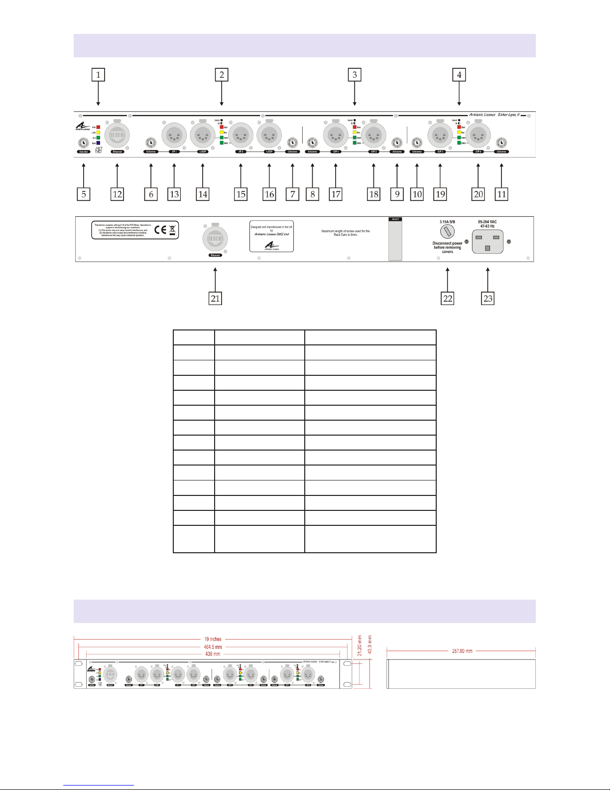
and Universe wheel selectors (note that the
Universe number of each DMX port can be
set independently), or remotely (see ‘Remote
Configuration’ below).
In contrast, Art-Net 3 and sACN can carry up
to 32768 and 65536 universes respectively.
To handle these large values, the concept
of a 16-bit port address including a ‘Net’
field is introduced. The port address of each
DMX512 universe is a number composed
of the (Net)+(Sub-Net)+(Universe).Because
the product has no ‘Net’ wheel selectors,
configuration must be done remotely if a port
address greater than 256 is required.
Note that settings made remotely override the
wheel selectors on the front panel.
Remote Configuration
By default, each port of the Ether-Lynx II has a
sequential universe number starting from zero.
There are two ways of remotely configuring
the product: 1) using DMX-Workshop or 2)
using the product’s internal web-server.
DMX-Workshop
DMX-Workshop™ is a software application
that runs on the Windows XP & Windows 7
platforms. It is free of charge and available via
download from the Artistic Licence website.
DMX-Workshop is a fully featured network
management, analysis, configuration and
diagnostics tool for Art-Net networks.
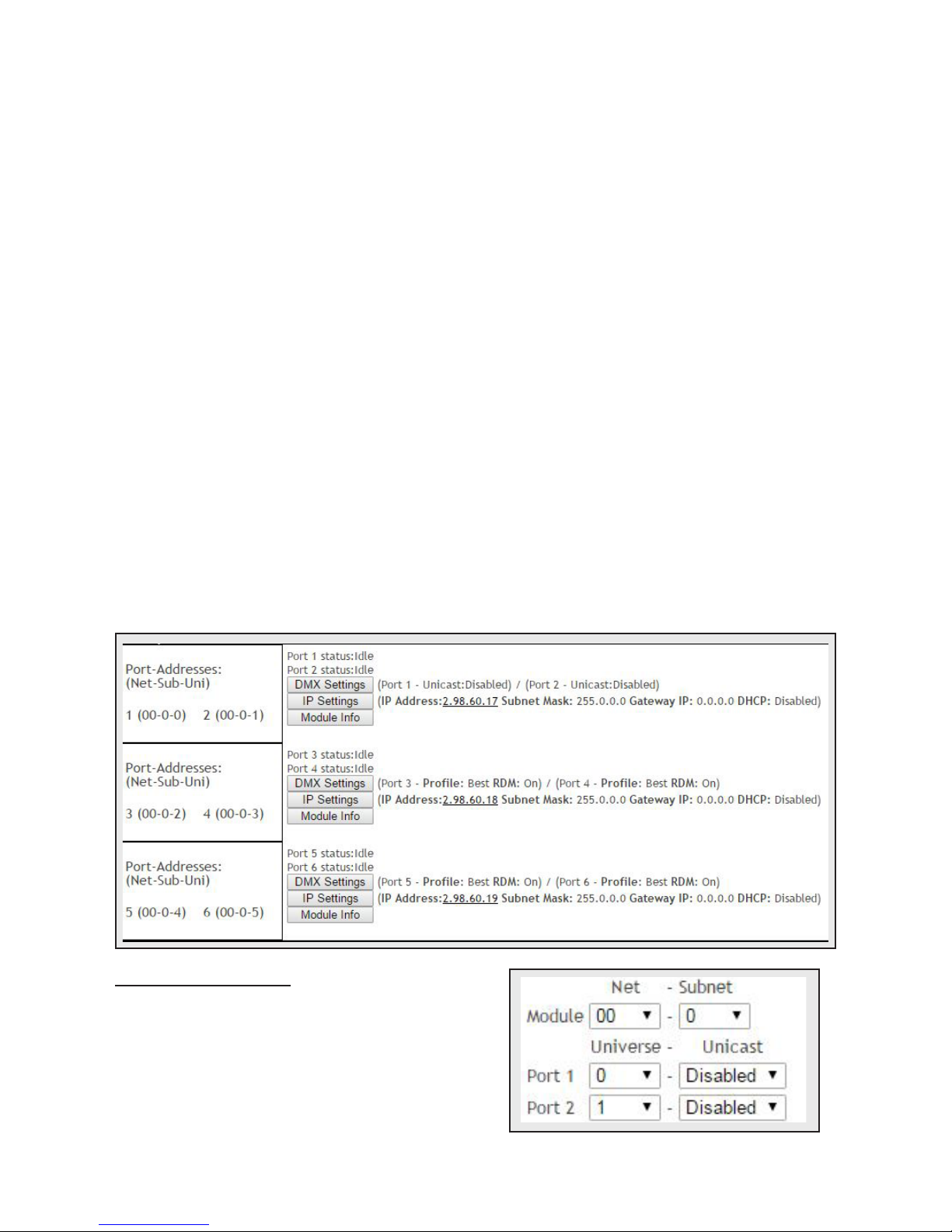
When Ether-Lynx II is connected to a computer
running DMX-Workshop, it should be detected
and displayed as an Art-Net node (click the
‘Node List’ icon to verify this).
The node can be expanded to show the
configuration and DMX port information, as
shown in the screen-shot opposite.
Right-clicking on any entry brings up a menu
that offers various functionality:
yThe ‘Configure Node’ option enables
configuration of the Universe, Sub-Net
and Net values. It also allows the user to
give the device a short and long name.
y‘Copy to clipboard’ enables all the node
information to be pasted into a support
request email.
y‘Merge Controls’ (selectable only on
individual DMX outputs) enables the
choice of LTP (latest takes preference)
or HTP (highest takes preference) merge
modes.
y‘Indicators’ enables selection of normal,
locate or mute for the front panel
LED indicators. Normal is the default
behaviour, locate causes the selected
port ‘Stat’ LED to flash, and mute turns
off all the LEDs.
y‘RDM Devices’ offers options for device
discovery on RDM networks.
y‘Advanced’ leads to ‘Programme Upload’
and ‘Configure IP Address’. These are
described in more detail below.
Firmware Upgrades
The ‘Programme Upload’ option enables
the user to upgrade the product’s firmware.
DMX-Workshop stores the firmware files
in C:\Program Files (x86)\Artistic Licence\
DMX-Workshop\Firmware\*.alf. Selection of
the desired file is made via a pop-up window
that shows the available files. Ensure that the
firmware upgrade is applied to all ports (check
the ‘Tick All’ box in the next window). Cycle
the power after a successful upload.
DMX-Workshop Node List
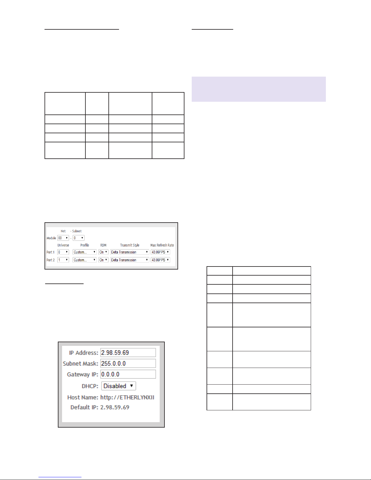
IP Address Configuration
Choosing the ‘Configure IP Address’ in the
‘Advanced’ menu brings up a window that
shows the IP and Subnet Mask.