AMX Corporation reserves the right to alter specifications without notice at any time.
For full warranty information, refer to the AMX Instruction Manual(s) associated with your Product(s).
036-004-2681 11/04 ©2004
AMX Corporation. All rights reserved. The AMX logo is a trademark of AMX Corporation. AMX reserves the right to alter specifications without notice at any time.
3000 RESEARCH DRIVE, RICHARDSON, TX 75082 • 800.222.0193 • fax 469.624.7153 • technical support 800.932.6993 • www.amx.com
93-2254 REV: F
Wiring the NXA-AVB connectors and cables
The inputs and outputs on the NXA-AVB are separated into a front and
rear connectors. The rear connectors are used to input external signals.
The front connectors are used to communicate signals between the
NXA-AVB and a Modero panel. FIG. 5 provides a layout of the wiring
connection both into and from the NXA-AVB Breakout Box.
Rear wiring connections:
•AUDIO IN: 6-pin mini-Phoenix connector, divided into left and right
audio channels. Each channel is divided into GND, IN+, and IN-
terminal cable connectors (2 sets of 3 for both channel sides).
An example of the cable used for this connector is to strip the ends of
2 RCA audio cables and insert them into their respective locations on
the Audio In port.
Either a balanced (+, -, and GND) or unbalanced (+ and GND) audio
signal can be connected to this input.
•MIC OUT: 4-pin mini-Phoenix connector, divided into GND, OUT-,
and OUT+ terminal connectors.
An example of the cable use for this connector is to strip the terminal
ends of a 3.5mm mini-jack and insert them into their respective
locations on the Mic Out port. This signal can be fed as a Line Level
In to either an amplifier or an AMX VOL card.
Either a balanced (+, -, and GND) or unbalanced (+ and GND) audio
signal can be connected to this output.
•Video In BNCs: Feeds either Composite/S-Video Luma or S-Video
Chroma signals into the NXA-AVB. This feed is then redirected out to
a Modero panel through the front Audio/Video port.
•ICSNet: RJ-45 connector routes data to the Modero through the front
ICSNet port. These connections use a standard CAT5 Ethernet cable
to provide communication between the touch panel, Breakout Box,
and NetLinx Master (not available on the CV7).
•PWR: 2-pin mini-Phoenix connector that connects to a PSN power
supply. This port can be used to provide power to a Modero panel by
sending it through the NXA-AVB (rear power connector through to the
front power connector).
Wiring the NXA-AVB for Unbalanced Audio
Most domestic audio equipment has unbalanced audio inputs and
outputs. This means that the audio output (left, right, or mono) appears on
a single wire, and is referenced to "0 V" or "Ground". Typical connectors
used are RCA "phono" connectors, DIN plugs/sockets, and 0.25" (6.3mm)
or 3.5mm jack plugs/sockets.
Unbalanced audio is adequate for most domestic environments and for
line-level signals in a typical broadcast studio. Problems may occur if the
signals are carried over long distances, especially if the source and
destination have separate main supplies. Use the following wiring drawing
(FIG. 6) to configure an unbalanced audio connection.
When using unbalanced audio for the AUDIO IN connector (FIG. 6),
the "-" and the "GND" terminals should be connected together and then
connected to the GND of the unbalance audio signal.
When connecting to an unbalanced audio input from the MIC OUT
connector (FIG. 6), wire the "+" terminal to the signal input, and the "GND"
terminal to the signal ground.
Description of Balanced Audio
Professional audio equipment will often use balanced audio inputs and
outputs, usually on 3-pin "XLR" connectors. A balanced audio signal
consists of a pair of wires carrying the audio signal in anti-phase with each
other (if one wire carries a positive voltage, the other carries an equal and
opposite negative voltage).
The advantage of balanced audio over unbalanced audio is its ability to
reject external interference added as the signal is carried over the wire.
The receiving equipment takes the voltage difference between the two
wires as the input signal. Interference will usually get added to both wires
equally, and so gets ignored by the receiving equipment.
The 3 wires used in a typical XLR lead are often referred to as Ground,
Live (Hot) and Return (Cold). "Live" and "Return" carry the "in-phase" and
"out-of-phase" versions of the audio respectively. The pins of the XLR
plug/socket are as follows:
• X = GROUND
• L = LIVE (Hot)
• R = RETURN (Cold)
When connecting the MIC OUT connector to a balanced audio input
(FIG. 7), use all three audio terminals (+, -, and GND), then connect the
"+" terminal to the "live" signal, the "-" terminal to the "return" signal, and
the "GND" terminal to the ground signal.
FIG. 5 NXA-AVB Breakout box connector wiring diagram
Microphone Out
(4-pin captive wire)
Audio In - Right Channel
(6-pin captive wire)
Audio In - Left Channel
(6-pin captive wire)
NXA-AVB
Breakout
Box
F
R
O
N
T
GND
Out (-)
Out (+)
R
E
A
R
Audio/Video
(CAT5)
ICSNet Out
(CAT5)
Power to
touch
panel
ICSNet In
(RJ-45)
Video In
(BNC)
GND
In (-)
In (+)
In (-)
In (+)
PSN power
GND
supply
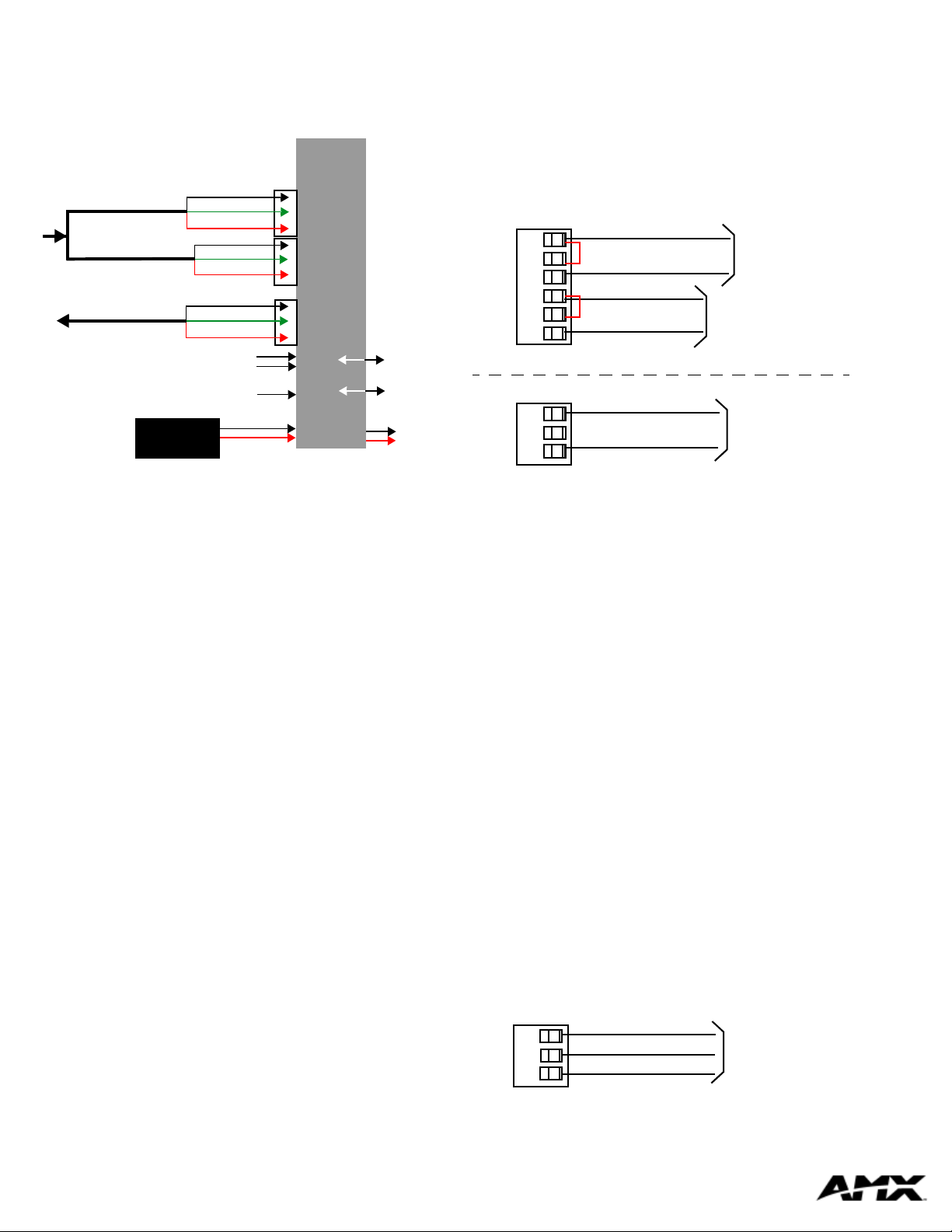
FIG. 6 Wiring the rear AUDIO IN and MIC OUT for use with Unbalanced Audio
FIG. 7 Wiring the rear MIC OUT connector for use with Balanced Audio
Unbalanced IN
GND
IN-
IN+
GND
IN-
IN+
Left Channel
Right Channel
(Jumper IN- to GND)
Unbalanced OUT
GND
OUT-
OUT+
Microphone
Unbalanced IN
(Jumper IN- to GND)
AUDIO IN
MIC OUT
Balanced OUT
GND
OUT-
OUT+
Ground signal
Return signal
Live signal


