ARTROMOT K3 User manual

Service Manual
Up to Serial number 2999
ARTROMOT®-K3

1. History 2
2. Purpose 2
3. General 2
4. Assembly and disassembly 3
5. Block diagram of electronic parts 3
6. Bill of material for service parts 4
7. How to perform the repair 8
8. Explosion drawing part 1 9
9. Explosion drawing part 2 10
10. Checklist for Function- and Safetytest 11
Revision Date Name Change
1 17.09.2001 M. Nunnenmacher Initial Release
2 19.09.2001 M. Nunnenmacher Pos. 4.8 new
partnumber
0.0013.104
3 15.10.2001 M. Nunnenmacher Pos. 1.9, 1.15,
1.16 new
partnumber
4 6.11.2001 M. Nunnenmacher Update
reference run,
new packaging
5 15.01.2002 M. Nunnenmacher Update Pos.
3.13, 3.45, 4.3,
4.5, Safetytest
6 06.02.2002 M. Nunnenmacher Update Pos.
3.12 Labeled
casting
7 27.03.2002 M. Nunnenmacher Update Pos.
1.1 part-
number power
cord
This service manual is to perform some repairs on
ARTROMOT®-K3 products. Repair and maintenance work
may only be carried out by authorised persons, as other-
wise all warranty services and liabilities shall be void.
It is not allowed to utilize any other spare part which is
not mentioned in chapter 6.
3.1 Electronic and cable
■Make sure that the characteristic values of your power
supply correspond to the voltage and frequency data
indicated on the power adapter.
■Error possibilities, showed by the Hand-held pro-
gramming unit:
Error 1: Spiral cable of the knee case is broken or not
connected
--> Verify the connection of the spiral cable or replace
the spiral cable.
3.2 Mechanics
■Do not loosen the knurled handles completely for any
adjustment. For operation or transport, make sure that
the knurled handles are tight.
3.3 Others
■Do not clean the housing or the support with grease
or oil.
■Do not utilize any solvent for cleaning the
ARTROMOT®-K3.
2
Table of contents 2. Purpose
3. General
1. History

Preparations for transport the ARTROMOT®-K3 has to be
done.
■The first step is to move the device in a maximum
position of EXTENSION = -5 degrees.
■Remove the power adapter and put this part in a
separate pad.
■Loosen the 2 knurled handles (Pos. 6.2), pull out the
ankle joint (Pos. 4.x) and put the ankle joint just the
other way round.
■Protect the hand-held programming unit against vibration
and damage and put the hand-held programming unit
in a separate pad.
■Make sure, that all of the knurled handles are tight.
■For transportation, use the original packaging.
3
4. Assembly and disassembly
5. Block diagram of the
electronic parts
Controller for
Programming unit.
Display
K3 electronics
Power adapter
Knee
adjustment

Position Description Order-Number
1.0 Electronics
1.1 Power adapter 115V 0.0031.107
1.1 Power adapter 115V / 230V 0.0031.107W
1.2 Hand-held programming unit 0.0032.123
1.3 Motor control 0.0031.101
1.4 Rubber mat 2.0031.195
1.5 Sheet metal cover 2.0031.116
1.6 Motor electronics 0.0031.120
1.7 Fantype lock washer 799.011
1.8 Screw thread slab 962.903
1.9 Screw LIKOM4x8A2
1.10 Metal distance reel 7E2.064
1.11 Hexagonal nut DIN934M3vz
1.12 Cable strap 0.0013.118
1.13 Cloth white 0.0010.144
1.14 Sticker 2.0013.362
1.15 Phillips screw 9B2.013
1.16 Cover top black 9B2.013
1.17 Spiral cable 2.0032.129
1.18 Holding clip 0.0031.004
2.0 Exterior underframe
2.1 Right profile 2.0032.107
2.2 Left profile 2.0032.106
2.3 Right rubber mat 2.0032.116
2.4 Left rubber mat 2.0032.115
2.5 Lip 2.0031.193
2.6 Interior slit 2.0032.113
2.7 Interior slit 2.0032.128
2.8 Right cover 2.0032.105
2.9 Left cover 2.0032.104
2.10 Shaft bearing 2.0031.112
2.11 DU collar 0.0031.110
2.12 Interior slit 2.0032.128
2.13 Fixing buckle 2.0031.184
2.14 Exterior slit 2.0032.114
4
6. Bill of material for service parts

5
2.15 Exterior slit 2.0032.114
2.16 Bottom plate 2.0032.108
2.17 Attachment plate femur bow 2.0032.101
2.18 Attachment plate femur bow 2.0032.100
2.19 Thread plate 962.901 M6
2.20 Pan head screw DIN912M6x8A2
2.21 Pan head screw DIN7984M5x25A2
2.22 Countersunk screw DIN7991M4x8A2
2.23 Cylinder pin DIN6325D5x10
2.24 Shell nut 0.0032.122
2.25 Countersunk screw DIN7991M6x10A2
2.26 Sping wire 0.0031.300
2.27 Band white 2.0020.163
2.28 Cloth black 0.0032.110
2.29 Inplementation spout 0.0031.145
2.30 Rivet DIN7337D4Al/ST
3.0 Drive technology
3.1 Motor including transmission 0.0031.100
3.2 Right slide 2.0031.108
3.3 Left slide 2.0031.109
3.4 Thread strut 2.0032.109
3.5 Rubber ring 2.0031.175
3.6 Rubber ring 2.0031.176
3.7 Rubber plate 2.0028.170
3.8 Motor plate 2.0031.156
3.9 Spline shaft drive 2.0031.181
3.10 Toothed belt 0.0031.130
3.11 Toothed lock washer drive 2.0031.180
3.12 Labeled Casting 2.0032.032
3.13 Bearing plate left 2.0031.165
3.14 Rubber plate 2.0031.102
3.15 Sheet metal 2.0031.115
3.17 Ball bearing 910.008
3.18 Rubber ring 2.0031.105
3.19 Rubber disk 2.0031.104
3.20 Joint plate 2.0031.113
3.22 Covering plate 0.0028.105
3.23 Ring 0.0028.106
3.24 Split rivet 0.0031.136
3.25 Wire-Set power supply 0.0031.125
3.26 Retaining ring DIN471A8x0,8
3.27 Rubber buffer 0.0031.109

3.28 Spacer sleeve 0.0031.104
3.29 Pin 2.0031.188
3.30 Countersunk screw DIN7991M5x20vz
3.31 Screw thread pin DIN916M4x4sw
3.32 Screw thread pin DIN914M4x4sw
3.33 Countersunk screw DIN7991M4x10vz
3.34 Hexagonal nut DIN934M5vz
3.35 Pan head crew DIN912M5x6vz
3.36 Countersunk screw DIN7991M5x25A2
3.37 Countersunk screw DIN7991M5x55vz
3.38 Countersunk screw DIN7991M5x16vz
3.39 Bearing plate right 2.0031.103
3.40 Retaining plate 2.0031.200
3.41 Pan head screw DIN912M4x10vz
3.43 Countersunk screw DIN965M3x4vz
3.44 Pan head screw DIN912M2,5x6vz
3.45 Spacer sleeve 0.0031.112
3.46 Pressure spring 0.0031.170
3.47 Case 2.0031.201
3.48 GS-Magnet 0.0031.160
3.49 Tube ring 0.0031.161
3.50 Countersunk screw DIN7991M4x16vz
3.51 Pan head screw DIN912M4x12vz
3.52 Plug 9A4.127
4.0 Ankle joint
4.1 Ankle joint bowl 2.0031.120
4.2 Base plate 2.0031.170
4.3 Knurled handle GN534-40-M6-10sw
4.4 Washer DIN9021D6,4vz
4.5 Washer 0.0031.111
4.6 Washer 0.0031.142
4.7 Screw rosette 0.0031.137
4.8 Spacer sleeve 0.0013.104
4.9 Sleeve nut 2.0031.178
4.10 Fastening band 0.0031.144
4.11 Rigid pipe 2.0031.117
4.12 Knurled handle 2.0031.031
4.13 Washer DIN7349D6,4vz
4.14 Hinge box 2.0031.119
4.15 Washer 2.0031.118
4.16 Countersunk screw DIN7991M5x8A2
4.17 Cylinder pin / DIN7D4x20A2
6

7
4.18 Nut 0.0031.108
4.19 Nut 0.0031.105
5.0 Knee case
5.1 Knee case 2.0032.125
5.2 Retaining ring DIN471A10x1
5.3 Bearing shell 2.0032.122
5.4 Washer 2.0032.123
5.5 Shim DIN988D10x16x0,1
5.6 Knee case 2.0032.119
5.7 Knee case (Poti) 2.0032.121
5.8 Knee electronics 0.0031.121
5.9 Spiral cable for knee case 0.0031.122
5.10 Lid potentiometer 2.0031.189
5.11 Shaft 2.0032.120
5.12 Countersunk screw DIN7991M4x12A2
5.13 Countersunk screw DIN7991M4x20A2
5.14 Tapping screw countersunk DIN7982D3,9x13A2
5.15 Screw thread pin DIN913M4x8sw
5.16 Washer 2.0013.231
5.17 Shim DIN988D10x16x0,3
6.0 Femur bow
6.1 Femur bow 2.0032.001
6.2 Knurled handle GN534-32-M6-10
6.3 Right pipe thigh 2.0032.004
6.4 Left pipe thigh 2.0032.006
6.5 Stop bow femur adjustment 2.0032.127
6.6 Support 2.0032.005
6.7 Washer DIN125D2,2A2
6.8 Washer DIN125D3,2A2
6.9 Hexagonal nut DIN934M2A2
6.10 Pin DIN1481D3x16A2
Patient kits
No illustration Patient kit fleece 2.0032.155
No illustration Patient kit cool-quilt 2.0032.155B

8
7. How to perform the repair
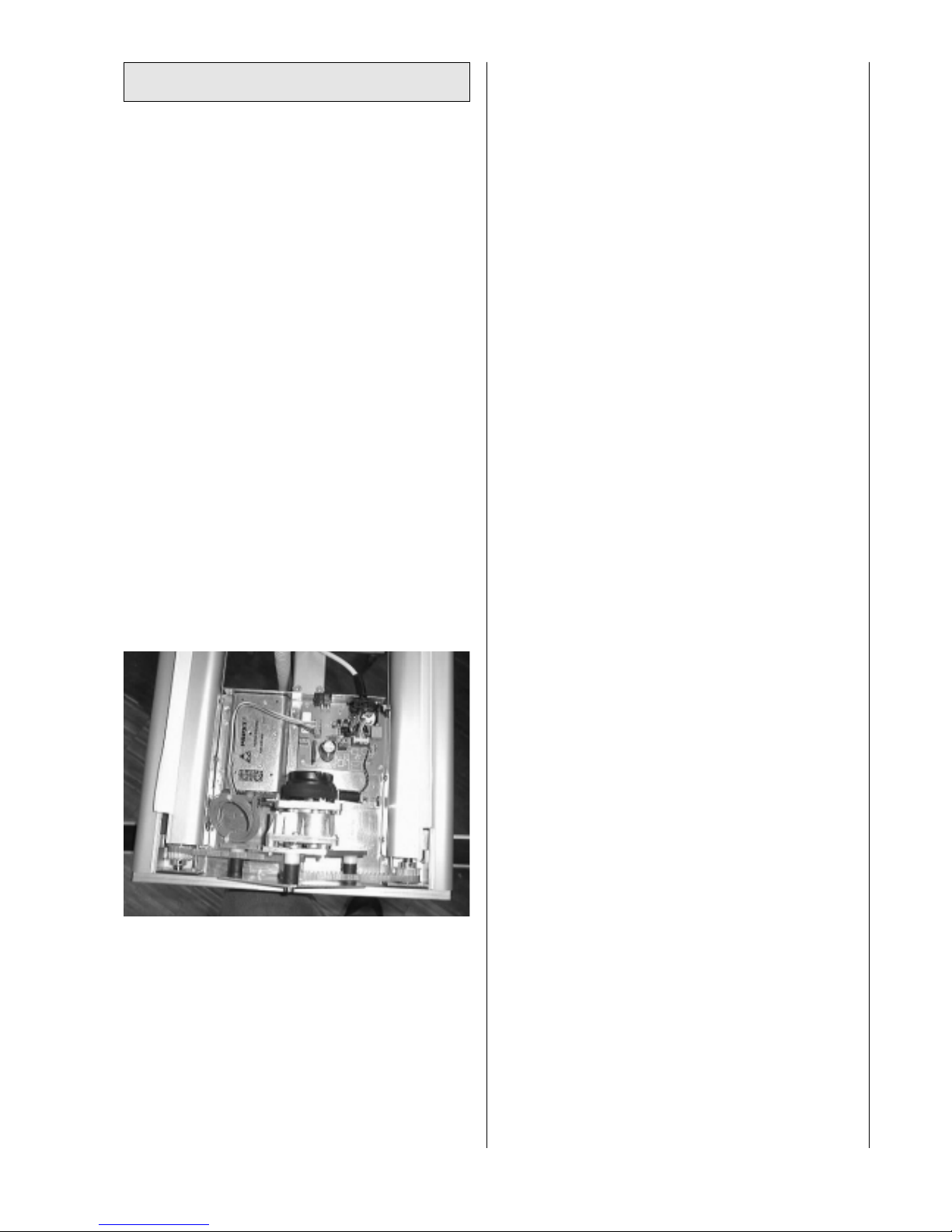
7.1 How to remove the casing (Pos. 3.12)
■Move the ARTROMOT®-K3 in a position of approximately
110 degrees.
■Turn the power OFF at the ARTROMOT®-K3 and remove
the power adapter.
■Hit the 4 pins of the split rivet (Pos. 3.24) inwards.
■Remove the 2 covering plates (Pos. 3.22)
■Loosen the 2 countersunk screws (Pos. 3.50) and remove
the casing.
■Remove the 4 pins of the split rivet, which are inside the
casing.
■If you have exchanged any of the printed circuit boards
including the knee elec-tronics and the hand held pro-
gramming unit or any parts of the drive technology (Pos.
3.x), you have to perform a reference run. See chapter 7.4
■Finally, a function- and safetytest has to be performed.
7.2 How to exchange the hand-held programming unit
(Pos. 1.2)
■Remove the casing. See chapter 7.1
■Pull out the connector of the hand held programming unit.
Attention: Use your ESD (Electro Static Discharge)-
equipment.
■Put in the connector of the new hand held programming
unit.
■Rebuild the casing.
■Perform a reference run. See chapter 7.4
■Finally, a function- and safetytest has to be performed.
7.3 How to exchange the motor electronics
(Pos. 1.3 and 1.6)
■Remove the casing. See chapter 7.1
■Pull out the required cables at the printed circuit board
(Pos. 1.6)
Attention: Use your ESD (Electro Static Discharge)-
equipment.
■Exchange the defect printed circuit board.
■Put in the cables at the same position. (Pay attention to
the code)
■Rebuild the casing.
■Perform a refernce run. See chapter 7.4
■Finally, a function- and safetytest has to be performed.
7.4 How to perform a reference run.
(Reference run connector: 0.0031.007)
■Move the ARTROMOT®-K3 in a position of approximately
10 degrees.
■Turn the power OFF at the ARTROMOT®-K3.
■Adjust a maximum femur length.
■Open the housing of the hand-held programming unit
vis-à-vis to the spiral cable side. At the printed circuit
board is an unused socket. Insert the reference run
connector at this socket. (Pay attention to the code)
■Turn the power ON at the ARTROMOT®-K3.
■The display shows „REFERENCE RUN"
■Press „START"
■After about 2 minutes, when the ARTROMOT®-K3
reached both points of changing direction, (first minimum
at EXTENSION = -5 degrees afterwards maximum at
FLEXION = 127 degrees) the ARTROMOT®-K3 will stop at
EXTENSION / FLEXION = 110 degrees.
Attention: It is important to push or pull at the femur
bow so that in direction Flexion the ARTROMOT®-K3
reach the mechanical stud. (approximately 3 cm in front of
the right/left cover). (Pos. 2.8/2.9)
■Pull out the reference run connector.
■Turn the power OFF at the ARTROMOT®-K3 and close
the housing of the hand-held programming unit.
■Finally, a function- and safetytest has to be performed.

9
8. Explosion drawing part 1

10
9. Explosion drawing part 2

11
10. Checklist for Function- und Safetytest
Safetytest Measuring Date/Signature
Enclosure Leakage Current EN60601-1/ VDE 0751 ≤100 µA µA
Or
Enclosure Leakage Current UL2601 (115 Volt) ≤100 µA µA
Functiontest OK Error
1. Turn the power ON at the ARTROMOT®-K3 and press "SET" .
Display: Software Version K3 V33 070600 (for the new generation of
hand-held programming units)
No display change (for the old generation of hand-
held programming units)
2. The set range of motion for Extension/Flexion is from -5 to 110 degrees.
Verify the angle in a position of 0 degrees with a tolerance of +/- 5 degrees.
Verify the angle in a position of 60 degrees with a tolerance of +/- 5 degrees.
Verify the angle in a position of 105 degrees with a tolerance of +/- 5 degrees.
4. Safety - OFF Functions.
Start the ARTROMOT®-K3 in a continuos mode.
Press any of the buttons (with the exception of "SET", "+" and "-") to stop
the motor immediately. Verify this for all buttons.
6. Perform the following settings.
Extension: -5 degrees
Flexion: 110 degrees
Pause Ex.: 5 sec.
Pause Flex.: 10 sec.
Force: 45 kp
Speed: 100%
Adjust a maximum femur length.
7. First press "STOP" and afterwards press "START".
The ARTROMOT®-K3 should then reach both points of changing direction
within 50 to 65 seconds.
8. Change the speed to 50% and repeat test 7
The ARTROMOT®-K3 should then reach both points of changing direction
within 105 to 125 seconds.
9. Verify the settings for "Pause Ex." and "Pause Flex."
The tolerance for both is +/- 3 seconds.

DIN EN 46 001 ORMED Nr. 018 829-01
© ORMED 7/03
Ormed GmbH & Co. KG • Merzhauser Straße 112 • D -79100 Freiburg • Tel. 07 61/45 66-01
Fax 0761/45 66 55-01 • www.ormed.de • e-mail: info@ ormed.de
St. Paul/USA,Tel 001-800-4402784, Fax 001-651-4157405 • Prag/CR,Tel 02-84094650,
Fax 02-84094660 • Wien/A, Tel 01-53 20 83 40, Fax 01-53 20 83 431
Other manuals for K3
1
Table of contents
Other ARTROMOT Fitness Equipment manuals
Popular Fitness Equipment manuals by other brands

Nautilus
Nautilus PEC FLY owner's manual

ziva
ziva INFINITY WALL MOUNTED 125 Owner's manual & assembly instructions

Weba Sport
Weba Sport SWIM ERGOMETER operating manual

KingsBox
KingsBox Mighty Combo Rack CX-37 quick start guide

Slackers
Slackers Ninja Net manual

Coopers
Coopers Purple Exercise Ring Instructions for use