© 2020 ASCO Power Technologies. All Rights Reserved
For troubleshooting, call technical assistance at 1-800-237-4567 or customercare@ascopower.com
5
IO-70075
08/2020
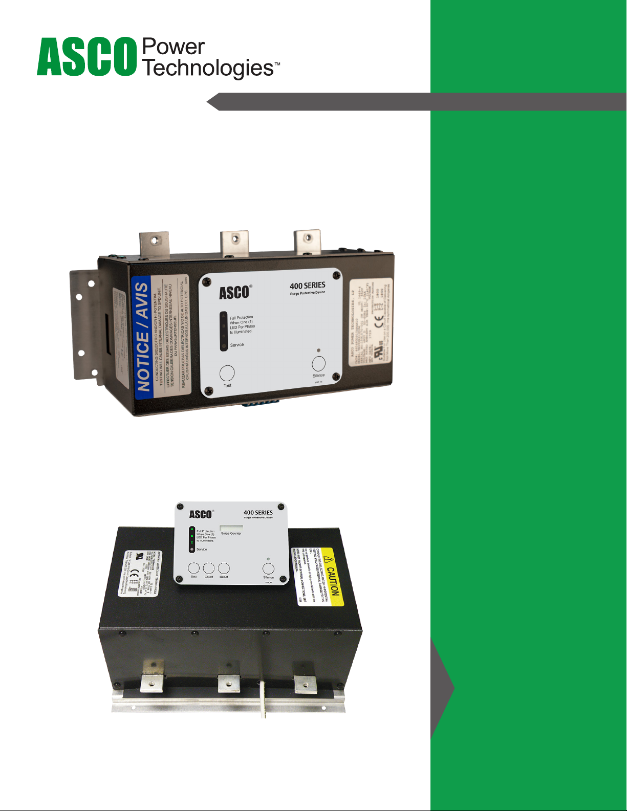
ASCO 450/451/452/453 Surge Protective Device (SPD)
Precautions
Precautions
HAZARD OF ELECTRIC SHOCK, EXPLOSION, OR ARC FLASH
• Apply appropriate personal protective equipment (PPE) and follow safe
electrical work practices. See NFPA 70E, NOM-029-STPS or CSA Z462.
• This equipment must only be installed and serviced by qualied electri-
cal personnel.
• Turn o all power supplying this equipment before working on or inside
equipment.
• Always use a properly rated voltage sensing device to conrm power is o.
• Replace all devices, doors and covers before turning on power to this
equipment.
• This equipment must be eectively grounded per all applicable codes.
Use an equipment-grounding conductor to connect this equipment to the
power system ground.
Failure to follow these instructions will result in death or serious injury.
NOTICE
LOSS OF BRANCH CIRCUIT POWER / LOSS OF SURGE
SUPPRESSION
• Perform periodic inspection of the surge protective device status
indicator lights as part of the preventative maintenance schedule.
• Promptly replace the surge protective device when an alarm state
exists.
• Use dry contacts to signal an alarm state to the central supervisory
system for unmanned, inaccessible, or critical installations.
• Use multiple surge protective devices to achieve redundancy for critical
applications.
Failure to follow these instructions can result in equipment damage.
At end-of-life conditions, Surge Protective Devices (SPDs) can lose their
ability to block power system voltage and attempt to draw excessive current
from the line. This SPD is equipped with overcurrent and overtemperature
components that will automatically disconnect the surge suppression ele-
ments from the mains should the surge suppression elements reach end of
life. Tripping of the branch circuit breaker or fuse feeding the SPD can occur
when the surge suppression elements reach end of life.
DANGER
HAZARD OF ELECTRIC SHOCK, EXPLOSION, OR ARC FLASH
• Do not energize the surge protective device until the electrical system is
completely installed, inspected and tested.
• Ensure all conductors are connected and functional.
• Verify the voltage rating of the device and system prior to energizing.
• Perform high-potential insulation testing, or any other tests where surge
protective device components will be subjected to voltages higher than
their rated turn-on voltage, with the neutral and surge protective device
disconnected from the power source
Failure to follow these instructions will result in death or serious injury.
DANGER