manuals.online logo
Brands
  1. Home
  2. •
  3. Brands
  4. •
  5. Asco
  6. •
  7. Controllers
  8. •
  9. Asco HYDRAMOTOR AH2D Series Installation and operating instructions

Asco HYDRAMOTOR AH2D Series Installation and operating instructions

Page 1 of 4
50-60 Hanover Road, Florham Park, New Jersey 07 32 www.ascovalve.com
eMCMXCIX All Rights Reserved.
Printed in U.S.A.
Installation & Maintenance Instructions
Form No.V8700R1
HYDRAMOTORr USH-TY E LINEAR ACTUATORS
AH2D
HYDRAMOTORr
ACTUATOR
SERIES
WARNING
To prevent the possibility of death, serious injury or
property damage, the Hydramotorr Actuator must be
installed and serviced only by a qualified service
technician avoiding the following hazards:
SElectrical hazard. Turn off all electrical power to
Hydramotorr Actuator. More than one circuit may
exist.
Sressure hazard. Depressurize valve and vent
hazardous or combustible fluid to a safe area before
inspection or removing the actuator or valve from
service.
SExplosion,Ă fire or toxic Ăgas Ăhazards. Extinguish all
open flames and avoid any type of sparking or
ignition during leakage testing.
NOTICE: See separate valve installation and maintenance
instructions for information on: Operation, Positioning,
Mounting, Piping, Strainer or Filter Re uirements, Flow
Controls, Preventive Maintenance, and Cause of Improper
Operation.
DESCRIPTION
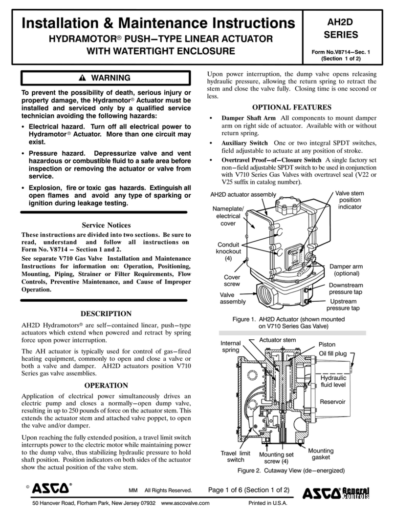
AH2D Hydramotorsr are self-contained linear, push-type
actuators which extend when powered and retract by spring
force upon power interruption.
The AH actuator is typically used for control of gas-fired
heating equipment, commonly to open and close a al e or
both a al e and damper. AH2D actuators position V710
Series gas al e assemblies.
OPERATION
Application of electrical power simultaneously dri es an
electric pump and closes a normally-open dump al e,
resulting in up to 250 pounds of force on the actuator stem. This
extends the actuator stem and attached al e poppet, to open
the al e and/or damper.
Upon reaching the fully extended position, a tra el limit switch
interrupts power to the electric motor while maintaining power
to the dump al e, thus stabilizing hydraulic pressure to hold
shaft position. Position indicators on both sides of the actuator
show the actual position of the al e stem.
Upon power interruption, the dump al e opens releasing
hydraulic pressure, allowing the return spring to retract the
stem and close the al e fully. Closing time is one second or
less.
OPTIONAL FEATURES
SDamper Shaft & Arm Shaft with all components to mount
damper arm on either side of actuator. A ailable with or
without return spring.
SAuxiliary Switch One or two integral SPDT switches,
field adjustable to actuate at any position of stroke.
SOvertravel Proof-of-Closure Switch A single factory set
non-field adjustable SPDT switch to be used in conjunction
with V710 Series Gas Val es with o ertra el seal (V22 or
V25 suffix in catalog number).
Figure 1. AH2D Actuator (shown mounted
on V710 series gas valve)
ACTUATOR
ASSEMBLY
COVER
COVER
SCREW
CONDUIT
KNOCKOUT STEM OSITION
INDICATOR
DAM ER
ARM
DOWNSTREAM
RESSURE TA
U STREAM
RESSURE TA
(O TIONAL)
AH2D
ELECTRICAL
VALVE
ASSEMBLY
(2)
NAME LATE/
Figure 2. Cutaway schematic
(de-energized position)
OIL FILL LUG
MOUNTING
ISTON
ACTUATOR STEM
HYDRAULIC
FLUID LEVEL
INTERNAL
RESERVOIR
S RING
SET SCREW (2)
TRAVEL LIMIT
SWITCH
HOLE IS SHOWN 90_ OUT OF
TRUE OSITION
50-60 Hanover Road, Florham Park, New Jersey 07 32 www.ascovalve.com
Form No.V8700R1
Page 2 of 4
SPECIFICATIONS
Force Output: 250 lbs
Stroke: 1 1/8I
Electrical Characteristics:
Operating Amperes (nominal)
Operating
Voltage * Inrush Running Holding
24V/50-60Hz
120V/50-60Hz
240V/50-60Hz
28.00
5.60
2.80
8.00
1.85
0. 2
0.73
0.11
0.05
*50 Hz construction increases opening time 20%.
Opening Time: Fast Opening: 6 to 14 seconds
Slow Opening: 14 to 26 seconds
Note: Opening time doubles between -30_F to -40_F
(-34_C to -40_C). Timing not field adjustable.
Maximum Closing Time: One second
Temperature Limitations: Ambient -40_F to 150_F
(-40_C to 66_C)
Damper Arm Rating: Dri es damper in one direction only.
20 lb maximum at 2.85 in. radius at 20_F to 150_F
(-7_C to 65_C ) and 10 lb maximum at -40_F to 20_F
(-40_C to -7_C).
Damper Arm Travel: 2I maximum
INSTALLATION
Before installation, check nameplates to erify actuator and
al e selected are appropriate for the application.
IMPORTANT: After actuator installation, test all functions
and check out complete system before putting actuator/valve
into service.
Positioning/Mounting
Follow the V710 Series Gas al e and/or damper
manufacturer's instructions when installing the Hydramotorr.
1. AH2D actuators can be installed to operate in any
position.
2. Position the actuator to operate the al e (and damper if
appropriate), and secure with the two mounting set screws
(Figure 2). Torque set screws to 80 ± 5 in-lbs
[9,0 ± 0,5 Nm] using a 5/32I hex key wrench.
3. For damper applications requiring the damper arm to
return upon power failure, the optional return spring and
spring plug (kit 440006) must be installed on the damper
arm. Connect linkage so that damper returns to the
desired position.
Wiring
WARNING: Electrical hazard. To prevent the
possibility of death, serious injury or property
damage, open circuit before inspection, service or
disassembly. Reassemble before operating.
Wiring must comply with local codes and the National
Electrical Code. Limit controls must conform to actuator
rating ( oltage, amperage, hertz). Wire limit controls to the hot
side of power supply.
1. Remo e six screws and electrical co er.
2. Route wiring through one of the conduit knockout
openings. Install appropriate electrical fittings.
3. Connect the power wiring to terminals N (neutral) and L1
(hot). A green grounding screw with a cup washer is
pro ided beside the terminal strip for grounding.
(Figure 3).
4. Torque terminal screws to 8-12 in-lbs [0,9-1,3 Nm].
5. Connect auxiliary or al e o ertra el proof-of-closure
switch wiring to the common and normally open or
normally closed switch terminals (Figure 3).
6. Reinstall electrical co er on actuator housing.
7. Operate system through fi e cycles to erify proper
operation.
Figure 3. Typical AH2D Actuator Wiring.
NC
NO
COMM
Travel limit switch
Auxiliary or overtravel proof-of-closure switch
Grounding screw with cup washer
N
L1
1
2
3
4
LINE VOLTAGE
C
NO
Auxiliary and Overtravel Proof-of-Closure
Switch Ratings
15 Amps 120 Vac
7.5 Amps 240 Vac
Total connected load of auxiliary and o ertra el
proof-of-closure switches not to exceed 1800 VA.
CAUTION: Overtravel roof-of-closure switch
must only be used with V710 Series Gas Valves
having an overtravel seal (V22 or V25 Suffix in catalog
number).
Overtravel Proof-of-Closure Switch
The optional al e o ertra el proof-of-closure switch is set at
the factory to pro ide both a mechanical and electrical means
of pro ing al e closed position interlock to the primary
control. This switch is not to be field adjusted.
Page 3 of 4Form No.V8700R1
50-60 Hanover Road, Florham Park, New Jersey 07 32 www.ascovalve.com
Auxiliary Switch Adjustment
1. Remo e the window (Figure 4).
2. Loosen the camlock screw no more than 1/2 turn.
3. Reset the cam adjustment screw to the desired switching
point.
4. Tighten the camlock screw. Cycle the actuator to erify
the switch setting and readjust as required.
5. Reinstall the window and torque screws e enly to 14-16
in-lbs [1,6-1,8 Nm].
Figure 4. Auxiliary Switch Adjustment
MAINTENANCE
Maintenance should include periodic inspection and cleaning.
Use a cleaning fluid compatible with actuator components to
remo e dirt and oil. Organize a maintenance schedule based
on en ironment and frequency of use. Check for loose
electrical and mechanical connections and replace damaged
lead wires.
Field Service Notice
Field service replacement kits are limited to the following:
1. Tra el limit switch Replacement Kit 440000 (AH2D).
2. Left-hand auxiliary switch Replacement Kit 440002.
3. Right-hand auxiliary switch Replacement Kit 440003.
4. O ertra el proof-of-closure switch Replacement Kit
440004. See separate AH series actuator o ertra el
proof-of-closure switch replacement kit installation
instructions.
5. Damper shaft Replacement Kit 440005.
6. Damper arm Replacement Kit 440006 (with spring and
spring plug) or 440007 (without spring and spring plug).
7. Oil Replacement Kit 440008.
To order, specify the kit or part number, as well as the actuator
model and serial numbers.
Travel Limit Switch Replacement
1. Remo e the six co er screws and the co er plate
(Figure 1)
2. Disconnect actuator and switch wiring. Remo e two
mounting screws and the limit switch (Figure 2).
3. Install the new switch and reconnect wiring. The required
stroke is 1 1/8I ± 1/16I. Turn adjustment screw located
abo e limit switch until the desired stroke is achie ed.
Turn the adjustment screw clockwise to decrease stroke
and counterclockwise to increase stroke. Operate the
actuator a few times to erify proper adjustment.
4. Reinstall the co er plate and screws.
Auxiliary Switch Replacement
1. Remo e six co er screws and the co er plate (Figure 1).
2. Disconnect switch wiring. Remo e two mounting screws
and old switch wiring and install new switch.
3. Wire and adjust switch as instructed under Switch
Adjustment.
4. Install actuator on al e and torque set screws to 80 ± 5
in-lbs [9,0 ± 0,5 Nm] using a 5/32I hex key wrench.
BUSHING (2)
RETAINING RING (1)
DAM ER
RETAINING
RING (6)
SHAFT (3)
RETAINING
RING (6)
S RING (8)
S RING
LUG (9)
DAM ER
DAM ER ARM
OSITIONER (4)
ARM (7)
Figure 5. Damper Shaft and Damper Arm Kits
BUSHING (5)
Damper Shaft Installation (Figure 5)
The damper shaft can be installed with the damper arm on
either side of the actuator.
1. Loosen the two mounting set screw (Figure 2) and lift the
actuator from the al e.
2. Install the retaining ring (1) and bushing (2) on the
damper shaft (3).
3. Install the damper arm positioner (4), then slide the
damper shaft (3) through the actuator and positioner.
4. Install bushing (5) and secure with retaining ring (6).
5. Reconnect the wiring, restore power, and cycle the
actuator to erify proper operation.
50-60 Hanover Road, Florham Park, New Jersey 07 32 www.ascovalve.com
Form No.V8700R1
Page 4 of 4
Damper Arm Installation (Figure 5)
Kit 440006 (with return spring and plug)
Kit 440007 (without return spring and plug)
1. Remo e retaining ring (6).
2. Install damper arm (7).
3. Install return spring (8) and spring plug (9) if required
(440006 only).
4. Secure the assembly with the retaining ring (6) remo ed
in step 1, abo e.
5. Reconnect the wiring and cycle the actuator to erify
proper operation.
Refilling Hydramotorr Actuator with Hydraulic Oil
and Purging Entrapped Air
1. When refilling a Hydramotorr Actuator with oil, it is
recommended that the actuator be energized and
de-energized during filling (if possible). This is
particularly important if the oil le el in the reser oir is
ery low or empty. By operating the actuator, entrapped
air is purged from the hydraulic system. If upon
energizing the Hydramotorr Actuator the actuator fails
to mo e, delays or operates slowly, chances are air has
become entrapped in the hydraulic system.
Remo e entrapped air from the hydraulic system by
cycling the actuator 4 to 5 times successi ely o er the full
stroke. As air is purged, check oil le el and add oil if
necessary. All of the air has been remo ed when the
actuator stem mo es immediately upon energizing.
2. With Actuator Mounted Upright, (Figure 2), remo e oil fill
plug and fill to bottom of fill port, follow instructions
pro ided in step 1.
3. With Actuator Mounted On Its Side, and oil fill plug
uppermost, remo e the oil fill plug. The oil le el should
be 5/8I from the top of the pump co er. Follow
instructions pro ided in step 1.
4. Reinstall fill plug and torque to 114-120 in-lbs [13-14
Nm].
5. If actuator has been repositioned, return unit to normal
orientation.
6. Before returning to ser ice, cycle the actuator to erify
proper operation.
Figure 6. Dimensions
5.18 [132]
Partial View Optional Damper
Optional damper
shaft and arm
∅2.38
∅[60]
Two set screws for
mounting to V710 valve
1.70 [43]
1.66 [42]
10.17 [258]
6.12 [155]2.77 [70]
6.17 [157]
8.65 [220]
3.16 [80]
∅.88 [∅22.2] conduit knockout for
1/2 conduit connection, 2 places

Other Asco Controllers manuals

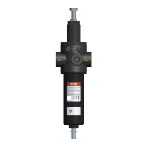
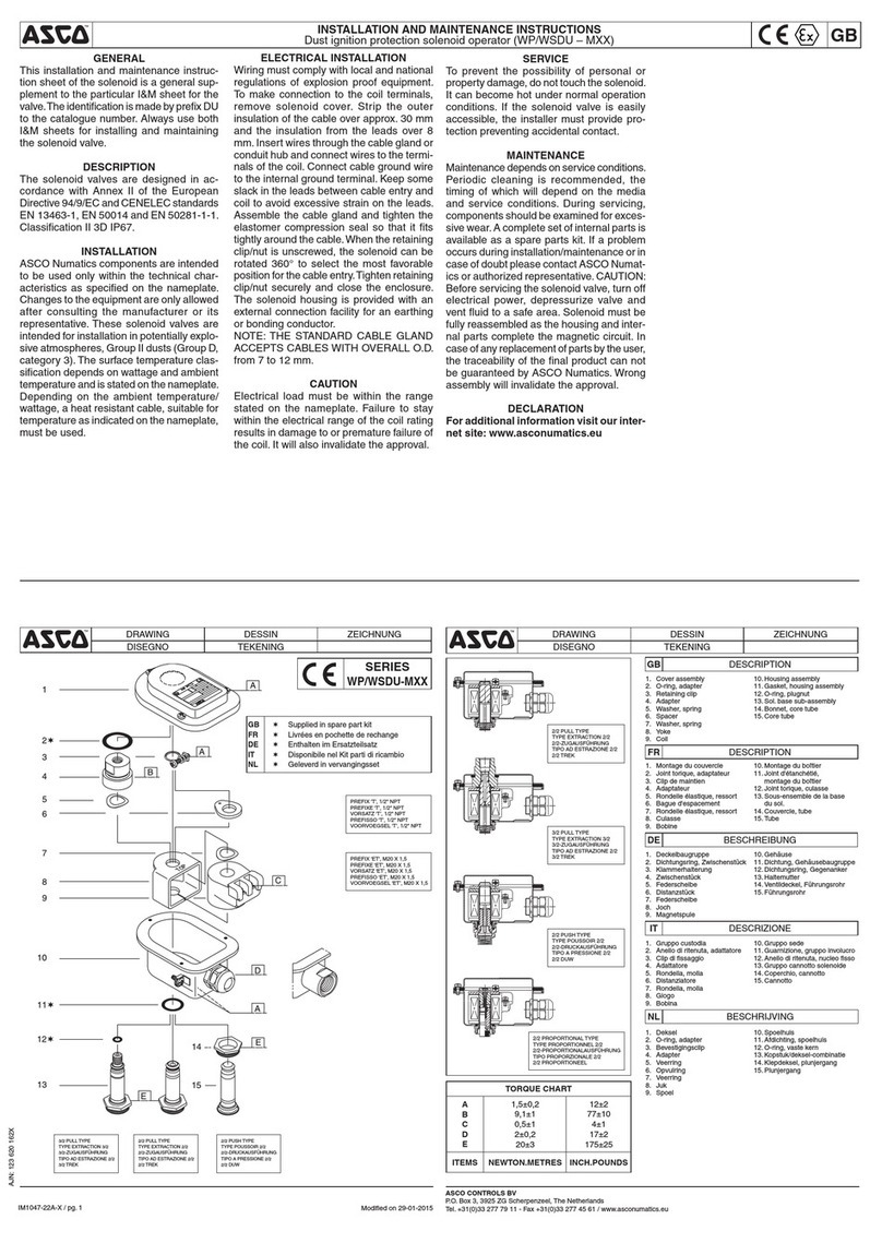
Asco WSDU-M Series User manual

Asco

Asco WSDU-M Series User manual

Asco 641 Series User manual

Asco

Asco 641 Series User manual

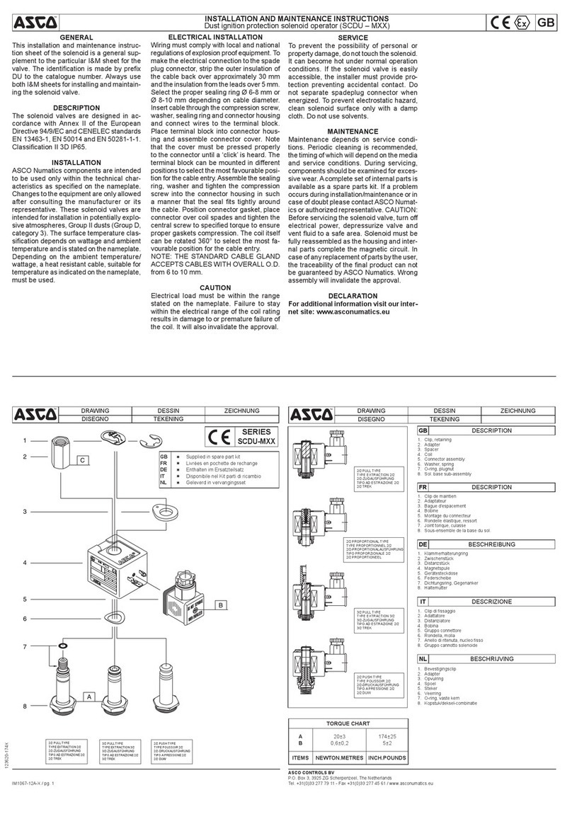
Asco SCDU-M Series User manual

Asco

Asco SCDU-M Series User manual

Asco 643 Series User manual

Asco

Asco 643 Series User manual

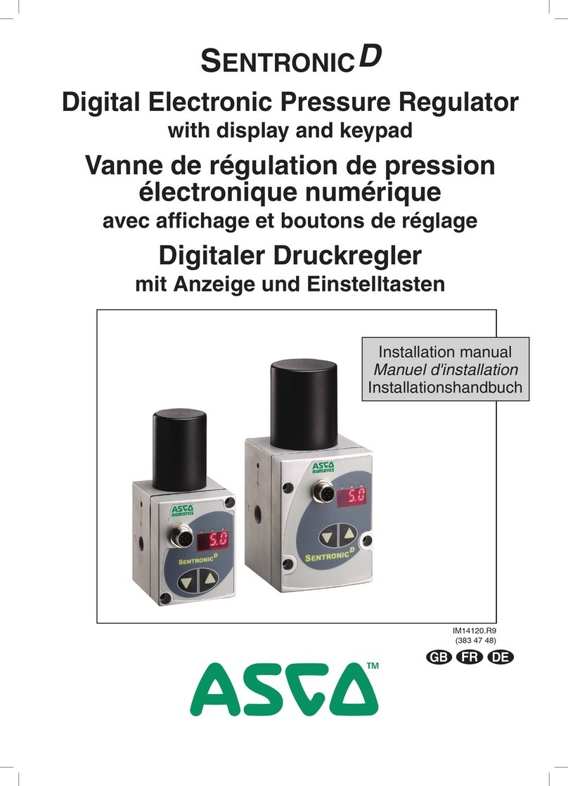
Asco SentronicD 608 Series User manual

Asco

Asco SentronicD 608 Series User manual

Asco Hydramotor AH2D Series User manual

Asco

Asco Hydramotor AH2D Series User manual

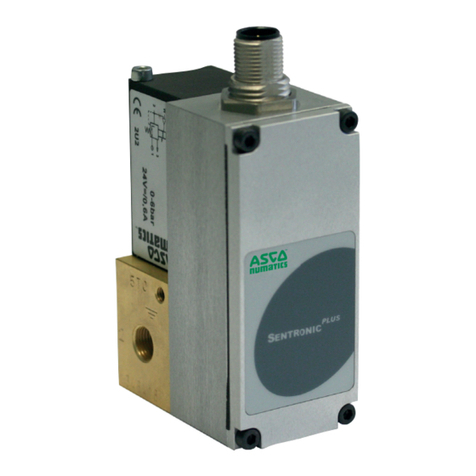
Asco Sentronic PLUS 614 Series User manual

Asco

Asco Sentronic PLUS 614 Series User manual

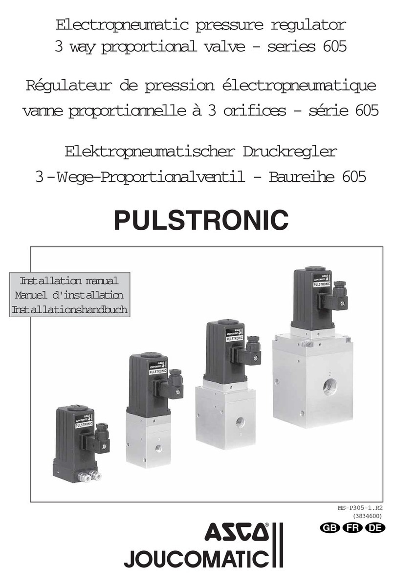
Asco JOUCOMATIC PULSTRONIC 605 Series User manual

Asco

Asco JOUCOMATIC PULSTRONIC 605 Series User manual

Asco 342 Series Installation and operating instructions

Asco

Asco 342 Series Installation and operating instructions

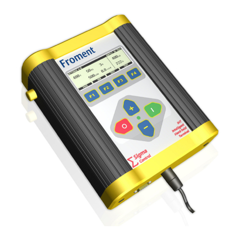
Asco Froment SIGMA IHT Version 4 User manual

Asco

Asco Froment SIGMA IHT Version 4 User manual

Popular Controllers manuals by other brands

Gardner Denver GD Connect 12 manual

Gardner Denver

Gardner Denver GD Connect 12 manual

Water Analytics AquaMetrix AM-2250 Installation and operation manual

Water Analytics

Water Analytics AquaMetrix AM-2250 Installation and operation manual

Festo VPPM Series operating instructions

Festo

Festo VPPM Series operating instructions

Xylem Bell & Gossett Technologic PPS quick start guide

Xylem

Xylem Bell & Gossett Technologic PPS quick start guide

BFT GIOTTO BT A 30-60S U Installation and user manual

BFT

BFT GIOTTO BT A 30-60S U Installation and user manual

Heatit Z-WATER2 Installer manual

Heatit

Heatit Z-WATER2 Installer manual

Lumiax MT1050 user manual

Lumiax

Lumiax MT1050 user manual

Distech Controls EC-BOS-8 installation guide

Distech Controls

Distech Controls EC-BOS-8 installation guide

Heinzmann StG 2120 Series manual

Heinzmann

Heinzmann StG 2120 Series manual

TECO-Westinghouse Motor Anab EQ5 Operation manual

TECO-Westinghouse Motor

TECO-Westinghouse Motor Anab EQ5 Operation manual

Raypak TempTracker B-21 Specifications

Raypak

Raypak TempTracker B-21 Specifications

Vega VEGATOR 131 operating instructions

Vega

Vega VEGATOR 131 operating instructions

LEVTECH LSP-SC2 user manual

LEVTECH

LEVTECH LSP-SC2 user manual

TLV Trapman instruction manual

TLV

TLV Trapman instruction manual

Sorel SFWC Installation and instruction manual

Sorel

Sorel SFWC Installation and instruction manual

PISCO RVF300 Series quick start guide

PISCO

PISCO RVF300 Series quick start guide

Chauvet ART-1CON user manual

Chauvet

Chauvet ART-1CON user manual

Belimo AMQB24-MFT quick start guide

Belimo

Belimo AMQB24-MFT quick start guide

manuals.online logo
manuals.online logoBrands
  • About & Mission
  • Contact us
  • Privacy Policy
  • Terms and Conditions

Copyright 2025 Manuals.Online. All Rights Reserved.