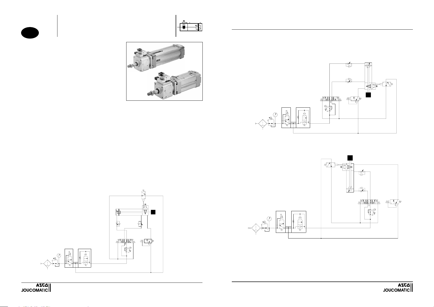
Asco 450 Series User manual

2
MONTAGE VERTICAL
Attention :
- Dans le cas où la personne habilitée souhaite actionner la commande manuelle (mettre en position "1" : déblocage manuel), elle doit s'as-
surer qu'il n'y a aucun danger en dessous de la charge (fig.2) ou entre la charge et le nez du vérin (fig.3)
W
14 12
135
42 2
31
W
14
42
12
31
2
1
5 3
Fig. 2 - Charge sous le vérin
Fig. 3 - Charge sur le vérin
SYSTEME ANTI-REDEMARRAGE MONTE
SUR VERIN AVEC DISPOSITIF DE BLOCAGE STATIQUE
CE DISPOSITIF N'EST PAS UN ORGANE DE SECURITE
Cde de
sortie
Cde de
rentrée
Cde de
sortie
Cde de
rentrée
(383 46 35)
MS-P238-2
FR
PRESENTATION
Le système anti-redémarrage permet de détecter la position de la
commande manuelle: il empêche le redémarrage du vérin lors de la
remise sous pression de l'ensemble vérin + dispositif de blocage si la
commande manuelle n'est pas remise en position normale de fonc-
tionnement (position "O").
PRINCIPE DE FONCTIONNEMENT
Ce système anti-redémarrage repose sur l'utilisation d'une microvalve
intégrée au dispositif de blocage, qui délivre un signal pneumatique
lorsque la commande manuelle est en position "déblocage".La gestion
autonome de ce signal pneumatique est assurée par le câblage pneu-
matique ci-dessous. Cette gestion autonome empêche le pilotage du
distributeur du vérin (redémarrage du vérin)
ASCO/JOUCOMATIC vous recommande vivement de suivre le
schéma de câblage ci-dessous pour le bon fonctionnement du
système anti-redémarrage
Séries 450-453
Type: PES-DM
CE DISPOSITIF N'EST PAS UN ORGANE DE SECURITE
SYSTEME ANTI-REDEMARRAGE MONTE
SUR
VERIN AVEC DISPOSITIF DE BLOCAGE STATIQUE
POSSIBILITES DE MONTAGE
La commande du vérin est effectuée par un distributeur 5/3 (ISO taille 1 pour les diamètres 32 - 40 - 50 mm et ISO taille 2 pour les diamètres
63 - 80 - 100 mm) à centre ouvert à l'échappement - Type W3 - (Fig.1) alimenté par les orifices d’échappement 3 et 5.
NOTA : 1)
La commande du dispositif de blocage statique doit s'effectuer par un électrodistributeur 3/2 NF afin d'assurer un blocage rapide
de la tige du vérin
2) Il est recommandé d'utiliser un régulateur de pression pour compenser l'effet de tige du vérin
3) Afin de contrôler la vitesse de déplacement de la tige, il est nécessaire d'utiliser des réducteurs de débit unidirectionnel
Précautions d'emploi de la commande manuelle de déblocage
Lors d'une coupure électrique ou d'air comprimé du dispositif de blocage, le dispositif de blocage maintient la tige du vérin. Il faut s'assurer
que les deux chambres du vérin sont mises à l'échappement avant d'actionner la commande manuelle de déblocage. La personne habilitée
peut débloquer la tige (mettre en position 1: déblocage manuel) et actionner manuellement la tige du vérin dans le sens qu'il souhaite.
Attention :
Avant de remettre en marche le vérin, il est obligatoire de remettre la commande manuelle en position normale (position "O")
Si la personne habilitée oublie de remettre la commande manuelle en position normale de fonctionnement (position "O"), la microvalve
ne délivrera pas de signal pneumatique au distributeur du vérin. Même si l'opérateur remet en marche le cycle, il pilote électriquement
le distributeur du vérin mais le vérin ne sera pas alimenté en pression: le système anti-redémarrage empêche le redémarrage du vérin.
Si la personne habilitée souhaite remettre en marche sa machine, il doit :
1) réinitialiser le cycle d'automate de sa machine
2) remettre la commande manuelle en position normale de fonctionnement (position "O")
3) remettre en dernier la remise progressive de la pression du réseau.
Lors d'un arrêt d'urgence (blocage de la tige en mouvement), il existe un risque de dégradation du matériel ! Il est donc important
de procéder à une vérification du système (dispositif de blocage, vérin, tige de vérin).
Il est conseillé de vérifier une fois par mois le fonctionnement correct des dispositifs de blocage statique:
- système de blocage - mécanisme du déblocage manuel
- système de détection - le fonctionnement du pilote
Fig. 1 -
Commande du vérin par distributeur 5/3
à centre ouvert à l'échappement (Type W3)
MONTAGE HORIZONTAL
4
5
14
3
1
12
2
31
2
W
Cde de
sortie Cde de
rentrée

2
W
14 12
135
42 2
31
Extend
control
Retract
control
VERTICAL MOUNTING
W
14
42
12
31
2
1
5 3
CYLINDER STARTUP INTERLOCK SYSTEM MOUNTED ON CYLINDER
WITH STATIC ROD-LOCKING DEVICE
THIS PRODUCT IS NOT A SAFETY COMPONENT
Caution:
In case the duly trained and qualified person wishes to operate the manual override (i.e.place it in position “1”:manual disengagement),
check the area underneath the load (fig. 2) or the area between the load and the cylinder nose (fig. 3) to make sure there is
no hazard.
Fig. 2 - Load underneath the cylinder
Extend
control
Retract
control
Fig. 3 - Load on top of the cylinder
1
4
5
14
3
1
12
2
31
2
W
GB
PRESENTATION
The startup interlock system allows detection of the position of the
manual override. It prevents the cylinder from starting up when pres-
sure is re-applied to the unit consisting of cylinder + rod lock device in
case the manual override has not been returned to its normal operation
position (position "0").
OPERATING PRINCIPLE
The startup interlock system uses a microvalve which is integrated
in to the rod lock device and supplies an air signal when the manual
override is in the "disengage" position.The autonomous processing of
this air signal is ensured by the pneumatic cabling shown below. The
autonomous processing prevents cylinder's valve from being supplied
with pilot pressure to startup the cylinder.
ASCO/JOUCOMATIC strongly recommends that you follow the
cabling diagram shown below to ensure the proper function of
the startup interlock system.
Series 450-453
Type: PES-DM
CYLINDER STARTUP INTERLOCK SYSTEM
MOUNTED ON CYLINDER WITH STATIC
ROD-LOCKING DEVICE
MOUNTING OPTIONS
The cylinder is controlled by a 5/3 valve (ISO size 1 for diameters 32, 40 and 50 mm, ISO size 2 for diameters 63, 80 and 100 mm),
with centre open to exhaust (type W3 - fig.1), and supplied by exhaust ports 3 and 5.
NOTE: 1) The static rod lock must be activated by a 3/2 NC solenoid valve to ensure fast braking of the cylinder rod.
2) It is recommended to use a pressure regulator to compensate for the cylinder's "rod effect".
3) One-directional flow reducers must be used to control the rate of speed of the rod.
Safety precautions when using the manual override:
In case of air pressure or power failure, the rod-locking device stops and holds the cylinder rod in place. Make sure both cylinder
chambers are exhausted before activating the manual lock-up override. Only a trained and qualified person may unlock the rod (i.e.
place the manual override in position 1: manual disengagement) and push the cylinder rod in the desired direction.
Caution:
Before starting up the cylinder again, the manual override must be returned to its normal operating position (position “0”). If the trained
and qualified person forgets to return the manual override to its normal operating position (position "0"), the microvalve will not supply
an air signal to the cylinder's valve. Though the cylinder's valve is electrically piloted when the operator starts up the cycle again, no
air is supplied to the cylinder: the startup interlock system will prevent the cylinder from starting up again.
If the trained and qualified person wishes to start up the machine again he must:
1) re-initialise the automatic cycle of his machine;
2) return the manual override to its normal operation position (position "0");
and finally
3) progressively re-pressurise the system.
Risk of damage to equipment in case of emergency shutdown (blocking of rod in motion)! The system (rod-locking device, cylinder,
cylinder rod) must therefore be checked prior to putting it back into operation.
It is recommended to check the correct operation of the static rod-locking devices once a month:
- rod-lock system - manual lock-up override mechanism
- position detection system - pilot valve function
HORIZONTAL MOUNTING
Fig. 1
Cylinder control with a 5/3 valve, centre
open to exhaust
(type W3)
Retract
control
Extend
control
THIS PRODUCT IS NOT A SAFETY COMPONENT

2
VERTIKALE MONTAGE
Achtung:
Beim Betätigen der Handhilfsbetätigung durch eingewiesenes Fachpersonal (Handhilfsbetätigung in die Position "1": manuelles Lösen) ist
der Bereich unterhalb der Last (Abb. 2) bzw. zwischen der Last und der Nase des Zylinders (Abb. 3) zu überprüfen, um jegliche Gefährdung
auszuschließen.
W
14 12
135
42 2
31
W
14
42
12
31
2
1
5 3
Abb. 2 - Last unterhalb des Zylinders
Abb. 3 - Last auf dem Zylinder
WIEDEREINSCHALTSPERRE AUF ZYLINDER MIT STATISCHER KLEM-
MVORRICHTUNG
DIESES PRODUKT IST KEINE SICHERHEITSVORRICHTUNG
Ausfahr-übe-
rwachung
Einfahr-überwa-
chung
Ausfahr-übe-
rwachung
Einfahr-überwa-
chung
1
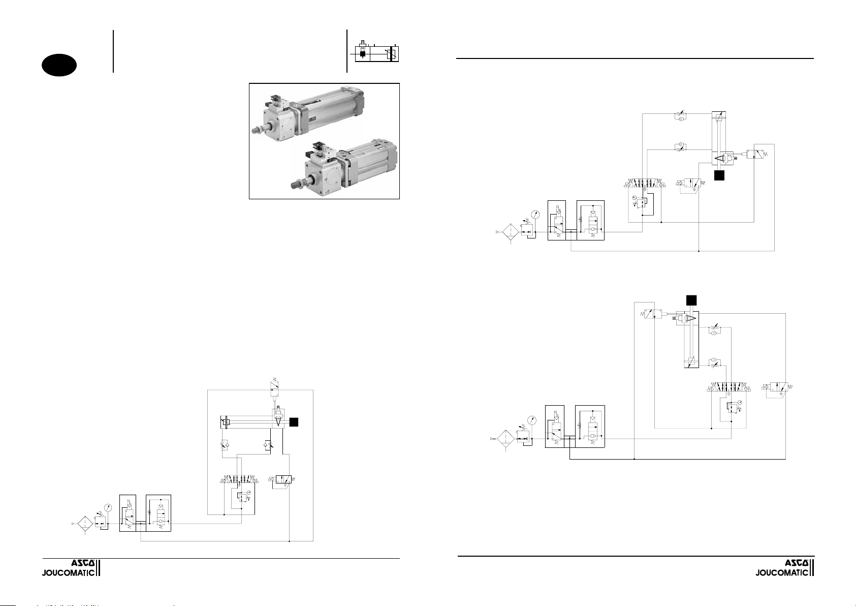
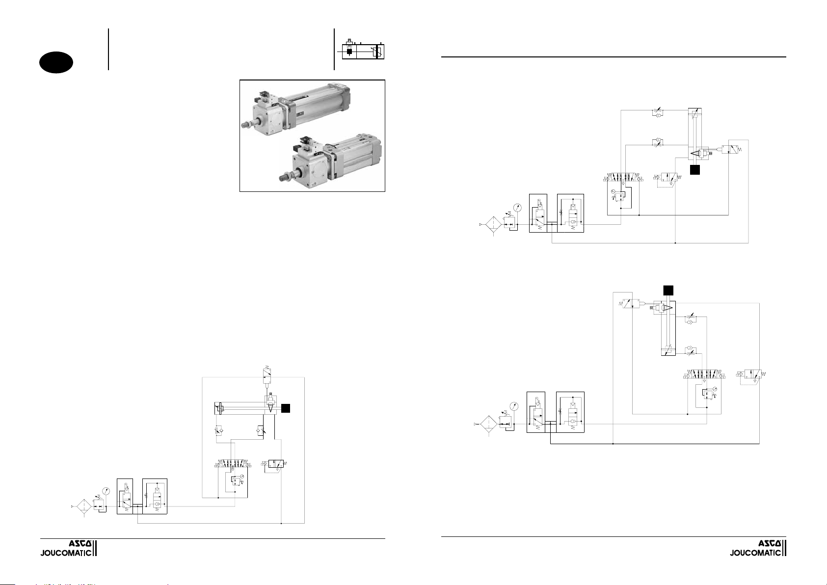
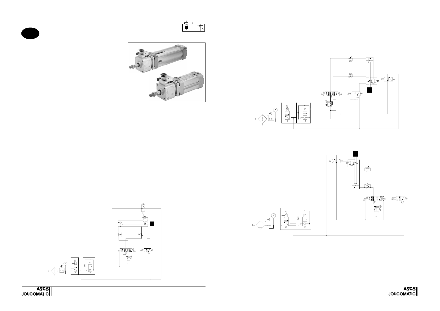
MONTAGEMÖGLICHKEITEN
Der Zylinder wird mit einem 5/3-Ventil (ISO Größe 1 für Durchmesser 32 – 40 – 50 mm und ISO Größe 2 für Durchmesser 63 – 80 – 100
mm) Entlüftungsanschluss in Mittelstellung geöffnet – Typ W3 – (Abb. 1) gesteuert und über die Entlüftungen 3 und 5 versorgt.
ANMERKUNG: 1) Die statische Klemmvorrichtung ist über ein 3/2-Magnetventil NC anzusteuern, um ein schnelles Festsetzen der
Kolbenstange zu gewährleisten.
2) Um den Kolbenstangeneffekt auszugleichen, wird die Verwendung eines Druckreglers empfohlen.
3) Zur Überwachung der Geschwindigkeit der Kolbenstange sind Abluftdrosseln zu verwenden.
Vorsichtsmaßnahmen bei der Verwendung der Handhilfsbetätigung
Bei einem Ausfall der Strom- oder Luftversorgung wird die Kolbenstange durch die Klemmvorrichtung festgesetzt und fixiert. Vor
Betätigung der Handhilfsbetätigung für die Freigabe ist sicherzustellen, dass beide Zylinderkammern entlüftet sind. Nur eingewiese-
nem Fachpersonal ist es gestattet, die Kolbenstange wieder zu lösen (Position "1": manuelles Lösen) und die Kolbenstange in die
gewünschte Richtung zu schieben.
Achtung:
Bevor der Zylinder wieder angefahren wird, muss die Handhilfsbetätigung wieder in die normale Betriebsposition (Position "0") zurüc-
kgestellt werden. Wird die Handhilfsbetätigung nicht vom Fachpersonal in die normale Betriebsposition (Position "0") zurücksetzt,
liefert das Micro-Ventil kein pneumatisches Signal an das Wegeventil des Zylinders. Beim Wiedereinschalten des Betriebszyklus wird
zwar das Wegeventil elektrisch angesteuert aber der Zylinder wird nicht mit Druckluft versorgt: Die Wiedereinschaltsperre verhindert,
das der Zylinder anfährt.
Um die Anlage wieder in Betrieb zu nehmen, muss vom Fachpersonal folgendes sichergestellt werden:
1) Automatikzyklus der Anlage neu einschalten;
2) Handhilfsbetätigung in die normale Betriebsposition setzen (Position "0");
3) Pneumatik-Kreislauf anschließend progressiv mit Druckluft beaufschlagen.
Ein Notausfall (Blockieren der sich bewegenden Kolbenstangen) kann zu einer Beschädigung des Materials führen! Das System
(Klemmvorrichtung, Zylinder, Kolbenstange) muss deshalb vor der Wiederinbetriebnahme geprüft werden.
Die richtige Funktionsweise der statischen Klemmvorrichtung ist ein Mal im Monat zu überprüfen. Dabei ist folgendes zu
überprüfen:
- Klemmsystem - Handhilfsbetätigung
- Positionserfassung - Betrieb des Pilotventils
4
5
14
3
1
12
2
31
2
W
DE
ANWENDUNG
Mit der Wiedereinschaltsperre wird die Position der Handhilfsbetätigung
erfasst: Dadurch wird ein Wiederanfahren des Zylinders nach der Beaufs-
chlagung der Einheit aus Zylinder und Klemmvorrichtung verhindert, wenn
die Handhilfsbetätigung noch nicht in die normale Betriebsposition zurüc-
kgestellt wurde (Position "0").
FUNKTIONSWEISE
DieFunktionsweisederWiedereinschaltsperre beruht auf den Einsatzeines
in der Klemmvorrichtung integrierten Micro-Ventils, das ein pneumatisches
Signal liefert, sobald sich die Handhilfsbetätigung in der Lage "Lösen"
befindet. Die eigenständige Verarbeitung dieses pneumatischen Signals
wird über die nachstehende pneumatische Verkabelung sichergestellt und
verhindert, dass das Wegeventil des Zylinders (Anfahren des Zylinders)
angesteuert wird.
Um die richtige Betriebsweise der Wiedereinschaltsperre zu gewähr-
leisten, wird empfohlen, sich an das nachstehende Verkabelungss-
chema zu halten.
Baureihe 450-453
Typ: PES-DM
DIESES PRODUKT IST KEINE SICHERHEITSVORRICHTUNG
WIEDEREINSCHALTSPERRE AUF ZYLINDER
MIT STATISCHER KLEMMVORRICHTUNG
Abb. 1 -
Zylindersteuerung mit einem 5/3-Ventil in
Mittelstellung geöffnet (Typ W3)
HORIZONTALE MONTAGE
Einfahr-übe-
rwachung
Ausfahrüber-
wachung

2
MONTAGGIO VERTICALE
Attenzione:
Se l'operatore autorizzato vuole azionare il comando manuale (portare in posizione "1": sbloccaggio manuale), deve accertare che
non esiste alcun pericolo sotto il carico (fig. 2) o fra il carico e l'estremità del cilindro (fig. 3)
W
14 12
135
42 2
31
W
14
42
12
31
2
1
5 3
Fig. 2 - Carico sotto il cilindro
Fig. 3 - Carico sopra il cilindro
SISTEMA ANTI-RIAVVIAMENTO MONTATO
SULLO STELO CON BLOCCASTELO STATICO
QUESTO DISPOSITIVO NON E' UN DISPOSITIVO DI SICUREZZA
Com. di
uscita
Com. di
rientro
Com. di
uscita
Com. di
rientro
1
4
5
14
3
1
12
2
31
2
W
IT
PRESENTAZIONE
Il sistema anti-riavviamento permette di identificare la posizione del comando
manuale:impedisce il riavviamento del cilindro al momento della riattivazione
della pressione nel gruppo cilindro + bloccastelo se il comando manuale non
si trova nella normale posizione di funzionamento (posizione "0").
PRINCIPIO DI FUNZIONAMENTO
Il sistema anti-riavviamento si basa sull'uso di una microvalvola integrata
nel bloccastelo, che fornisce un segnale pneumatico quando il comando
manuale è in posizione di "sbloccaggio". La gestione autonoma del segnale
pneumatico è assicurata dal cablaggio pneumatico illustrato di seguito.
Tale gestione autonoma impedisce il pilotaggio del distributore del cilindro
(riavviamento del cilindro).
ASCO/JOUCOMATIC raccomanda vivamente di seguire lo schema di
cablaggio indicato di seguito per ottenere un buon funzionamento del
sistema anti-riavviamento.
Serie 450-453
Tipo: PES-DM
QUESTO DISPOSITIVO NON E' UN DISPOSITIVO DI SICUREZZA
SISTEMA ANTI-RIAVVIAMENTO MONTATO
SULLO STELO CON BLOCCASTELO STATICO
POSSIBILITA' DI MONTAGGIO
Il comando del cilindro è assicurato da un distributore 5/3 (ISO taglia 1 per i diametri 32 - 40 - 50 mm e ISO taglia 2 per i diametri
80 - 100 mm) con centro aperto allo scarico - Tipo W3 - (Fig.1) alimentato attraverso le vie di scarico 3 e 5.
NOTA : 1)
Il comando del bloccastelo statico deve essere effettuato mediante un elettrodistributore 3/2 NC per garantire il bloccaggio
rapido dello stelo del cilindro.
2) Si raccomanda di utilizzare un regolatore di pressione per compensare l'effetto dello stelo del cilindro.
3) Per controllare la velocità di spostamento dello stelo è necessario utilizzare dei regolatori di portata unidirezionali
Precauzioni d'impiego del comando manuale di sbloccaggio
In caso di interruzione della corrente elettrica o dell’aria compressa del bloccastelo, quest’ultimo si arresta e trattiene lo stelo del
cilindro. Bisogna accertarsi che le due camere del cilindro vengono messe in stato di scarico prima di azionare il comando manuale
di sblocco. L’operatore autorizzato può sbloccare lo stelo (portare in posizione 1: sbloccaggio manuale) e azionare manualmente lo
stelo del cilindro nella direzione richiesta.
Attenzione
Prima di riavviare in moto il cilindro è indispensabile rimettere il comando manuale nella posizione normale (posizione “0”). Se l’ope-
ratore autorizzato dimentica di rimettere il comando manuale nella posizione di funzionamento normale (posizione “0”), la microval-
vola non fornisce alcun segnale pneumatico al distributore del cilindro. Anche se l’operatore riarma il ciclo, il distributore del cilindro
viene pilotato elettricamente ma il cilindro non sarà alimentato in pressione: il sistema anti-riavviamento impedisce la riattivazione
del cilindro.
Se l’operatore autorizzato vuole riavvviare la macchina deve:
1) inizializzare nuovamente il ciclo automatico della macchina;
2) rimettere il comando manuale nella posizione di funzionamento normale (posizione “0”)
3) infine, ripristinare progressivamente la pressione della rete.
In caso di arresto d'urgenza (bloccaggio dello stelo in movimento) esiste un rischio di usura del materiale. Quindi è importante
procedere alla veifica del sistema (bloccastelo, cilindro, stelo del cilindro).
Si consiglia di verificare una volta al mese il corretto funzionamento del bloccastelo statico.
- sistema di bloccaggio - meccanismo di sbloccaggio manuale
- sistema di finecorsa - il funzionamento del pilota
Fig. 1 -
Comando del cilindro mediante distributore
5/3 a centro aperto allo scarico (Tipo W3)
MONTAGGIO ORIZZONTALE
Com. di
uscita Com. di
rientro

2
MONTAJE VERTICAL
Atención :
-
En el caso en el que la persona cualificada desea accionar el mando manual (colocar en posición "1" : desbloqueo manual), comprobar que
no hay ningún peligro por debajo de la carga (fig.2) o entre la carga y la nariz del cilindro (fig.3)
W
14 12
135
42 2
31
W
14
42
12
31
2
1
5 3
Fig. 2 - Carga bajo el cilindro
Fig. 3 - Carga sobre el cilindro
SISTEMA ANTI-REARRANQUE MONTADO
EN CILINDRO CON DISPOSITIVO DE BLOQUEO ESTÁTICO
ESTE DISPOSITIVO NO ES UN ELEMENTO DE SEGURIDAD
Mdo de
salida
Mdo de
entrada
Mdo de
salida
Mdo de
entrada
1
4
5
14
3
1
12
2
31
2
W
ES
PRESENTACIÓN
El sistema anti-arranque permite detectar la posición del mando ma-
nual: impide el arranque del cilindro durante la puesta bajo presión del
conjunto cilindro + dispositivo de bloqueo si el mando manual no es
puesto en posición normal de funcionamiento (posición "O").
PRINCIPIO DE FUNCIONAMIENTO
Este sistema anti-arranque se basa en la utilización de una microválvu-
la integrada al dispositivo de bloqueo, que libera una señal neumática
cuando el mando manual está en posición "desbloqueo". La gestión
autónoma de esta señal neumática está asegurada por el cableado
neumático de abajo. Esta gestión autónoma impide el pilotaje del dis-
tribuidor del cilindro (arranque del cilindro)
ASCO/JOUCOMATIC le recomienda seguir estrictamente el es-
quema de cableado de abajo para el buen funcionamiento del
sistema anti-rearranque
Series 450-453
Tipo: PES-DM
ESTE DISPOSITIVO NO ES UN ELEMENTO DE SEGURIDAD
SISTEMA ANTI-REARRANQUE MONTADO
EN CILINDRO CON DISPOSITIVO DE BLOQUEO
ESTÁTICO
POSIBILIDADES DE MONTAJE
El pilotaje del cilindro se realiza mediante un distribuidor 5/3 (ISO talla 1 para los diámetros 32 - 40 - 50 mm e ISO talla 2 para los diámetros
63 - 80 - 100 mm) de centro abierto al escape - Tipo W3 - (Fig.1) alimentado por los orificios de escape 3 y 5.
NOTA : 1) El pilotaje del dispositivo de bloqueo estático debe realizarse por un electrodistribuidor 3/2 NC con el fin de asegurar un
bloqueo rápido del vástago del cilindro
2) Se recomienda utilizar un regulador de presión para compensar el efecto de vástago del cilindro
3) Con el fin de controlar la velocidad de desplazamiento del vástago, es necesario utilizar reguladores de caudal
unidireccionales
Precauciones de utilización del mando manual de desbloqueo
Durante un corte eléctrico o de aire comprimido del dispositivo de bloqueo, el dispositivo de bloqueo mantiene el vástago del cilindro.
Es ne-
cesario asegurarse de que los dos alojamientos del cilindro son puestos a escape antes de accionar el mando manual de desbloqueo
.
Una persona cualificada puede desbloquear el vástago (colocar en posición 1 : desbloqueo manual) y accionar manualmente el vástago
del cilindro en el sentido que el desee.
Atención :
Antes de poner en marcha el cilindro, es obligatorio colocar el mando manual en posición normal (posición "O")
Si la persona cualificada olvida colocar el mando manual en posición normal de funcionamiento (posición "O"), la microválvula no
libera señal neumática al distribuidor del cilindro. Incluso si el operador vuelve a poner en marcha el ciclo, pilota eléctricamente el
distribuidor del cilindro pero el cilindro no será alimentado en presión: el sistema anti-arranque impide el arranque del cilindro.
Si la persona cualificada desea volver a poner en marcha su máquina, debe :
1) reinicializar el ciclo de autómata de su máquina
2) volver a colocar el mando manual en posición normal de funcionamiento (posición "O")
3) poner, por último, la puesta progresiva de la presión de la red.
Durante una parada de urgencia (bloqueo del vástago en movimiento), ¡ existe riesgo de degradación del material ! Por tanto, es
importante proceder a una verificación del sistema (dispositivo de bloqueo, cilindro, vástago de cilindro).
Se aconseja verificar una vez al mes el funcionamiento correcto de los dispositivos de bloqueo estático.
- sistema de bloqueo - mecanismo de desbloqueo manual
- sistema de detección - el funcionamiento del piloto
Fig. 1 -
Pilotaje del cilindro por distribuidor 5/3
de centro abierto al escape (Tipo W3)
MONTAJE HORIZONTAL
Mdo de
salida Mdo de
entrada

2
VERTICALE MONTAGE
Let op:
- In het geval dat de bevoegde persoon de handbediening wil activeren (in stand «1» zetten: handmatige ontgrendeling), ervoor zorgen
dat er geen enkel gevaar bestaat onder de last (fig. 2) of tussen de last en de neus van de cilinder (fig. 3).
W
14 12
135
42 2
31
W
14
42
12
31
2
1
5 3
Fig. 2 - Last onder de cilinder
Fig. 3 - Last op de cilinder
ANTIHERSTARTSYSTEEM GEMONTEERD
OP CILINDER MET STATISCHE STANGBLOKKEERDER
DEZE INRICHTING IS GEEN VEILIGHEIDSORGAAN
Bediening
heen
Bediening
retour
Bediening
heen
Bediening
retour
1
4
5
14
3
1
12
2
31
2
W
NL
UITVOERING
Met het antiherstartsysteem kan de positie van de handbediening
worden gedetecteerd: dit voorkomt dat de cilinder herstart wanneer de
cilinder + de stangblokkeerder weer onder druk worden gezet indien de
handbediening niet is teruggezet in de normale stand (stand "O").
WERKINGSPRINCIPE
Dit antiherstartsysteem berust op het gebruik van een microventiel dat
in de stangblokkeerder geïntegreerd is en dat een pneumatisch signaal
afgeeft wanneer de handbediening in de stand "ontgrendeling" staat.
Het autonome beheer van dit pneumatische signaal vindt plaats door
middel van de onderstaande pneumatische aansluiting. Dit autonome
beheer verhindert dat het schuifventiel van de cilinder bestuurd wordt
(herstarten van de cilinder).
ASCO/JOUCOMATIC raadt u ten zeerste aan het onderstaande
aansluitschema te volgen met het oog op de goede werking van
het antiherstartsysteem
Serie 450-453
Type: PES-DM
DEZE INRICHTING IS GEEN VEILIGHEIDSORGAAN
ANTIHERSTARTSYSTEEM GEMONTEERD
OP CILINDER MET STATISCHE STANGBLOKKEERDER
MONTAGEMOGELIJKHEDEN
De cilinder wordt bediend door middel van een 5/3 schuifventiel (ISO grootte 1 voor diameters 32 - 40 - 50 mm en ISO grootte 2 voor diameters
63 - 80 - 100 mm) met open middenstand tegenover de ontluchting - Type W3 - (Fig.1) die via de ontluchtingspoorten 3 en 5 wordt gevoed.
N.B.: 1) De statische stangblokkeerder wordt bediend door middel van een 3/2 NG magneetventiel met het oog op het snelle
blokkeren van de cilinderstang.
2) Wij raden aan een drukregelaar te gebruiken om het stangeffect te compenseren
3) Om de verplaatsingssnelheid van de stang te controleren, is het noodzakelijk om unidirectionele snelheidsregelventielen
te gebruiken
Voorzorgsmaatregelen voor de handbediende ontgrendeling
Bij een stroomonderbreking of een onderbreking van de persluchttoevoer van de stangblokkeerder stopt de stangblokkeerder en blo-
kkeert deze de cilinderstang.Verzeker u ervan dat de twee kamers van de cilinder worden ontlucht alvorens de handmatige bediening
van de ontgrendeling in werking te stellen. Een bevoegd persoon kan de stang ontgrendelen (houd in stand 1: handmatige ontgren-
deling) en beweeg de cilinderstang handmatig in de gewenste richting.
Let op:
Voordat u de cilinder weer in werking stelt, dient u de handbediening in de normale stand terug te zetten (stand «O»).
Indien de bevoegde persoon vergeet om de handbediening in de normale stand te zetten (stand «O»), levert het microventiel geen
pneumatisch signaal af aan het schuifventiel van de cilinder. Zelfs wanneer de bediener de cyclus weer in werking stelt, bestuurt
deze het schuifventiel van de cilinder elektrisch, maar wordt de cilinder niet voorzien van druk: het antiherstartsysteem voorkomt dat
de cilinder herstart.
Indien de bevoegde persoon de machine weer in werking wil stellen, dient hij:
1) de automatische cyclus van de machine opnieuw in gang te zetten
2) de handbediening in de normale stand te zetten (stand «O»)
3) als laatste de progressieve toevoer van de druk te herstellen.
Bij een noodstop (blokkering van de stang in beweging) bestaat het risico dat het materiaal verslechtert! Het is dus van belang dat
het systeem (stangblokkeerder, cilinder, cilinderstang) wordt gecontroleerd.
Wij raden aan een keer per maand te controleren of de stangblokkeerders goed functioneren.
- blokkeersysteem - mechanisme voor handmatige ontgrendeling
- detectiesysteem - de werking van de stuurinrichting
Fig. 1 -
Bediening van de cilinder door middel van
5/3 schuifventiel met open middenstand
tegenover de ontluchting (Type W3)
HORIZONTALE MONTAGE
Bediening
heen Bediening
retour
This manual suits for next models
2
Table of contents
Languages:
Other Asco Industrial Equipment manuals
Popular Industrial Equipment manuals by other brands

HunterDouglas
HunterDouglas Luxalon 84B installation instructions

Cold Jet
Cold Jet i3 MICROCLEAN 2 manual

woodmizer
woodmizer SLPCTD3.6 Safety, operation and maintenance manual

New lift
New lift CBM manual

Contec
Contec CONPROSYS CPS-PC341EC-1-9201 Reference manual

Ditch Witch
Ditch Witch FX20 Operator's manual

Premier Manufacturing Co.
Premier Manufacturing Co. 270PK Service guidelines

EL-CELL
EL-CELL ECC-Opto-Std user manual

HIK VISION
HIK VISION DS-K3Y501SX Series quick start guide

Flex-A-Seal
Flex-A-Seal 73 Installation, operation, maintenance guide

Alfalaval
Alfalaval AC instruction manual

PSS
PSS RoadQuake 2 Product guide