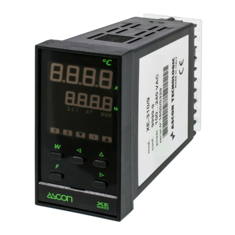
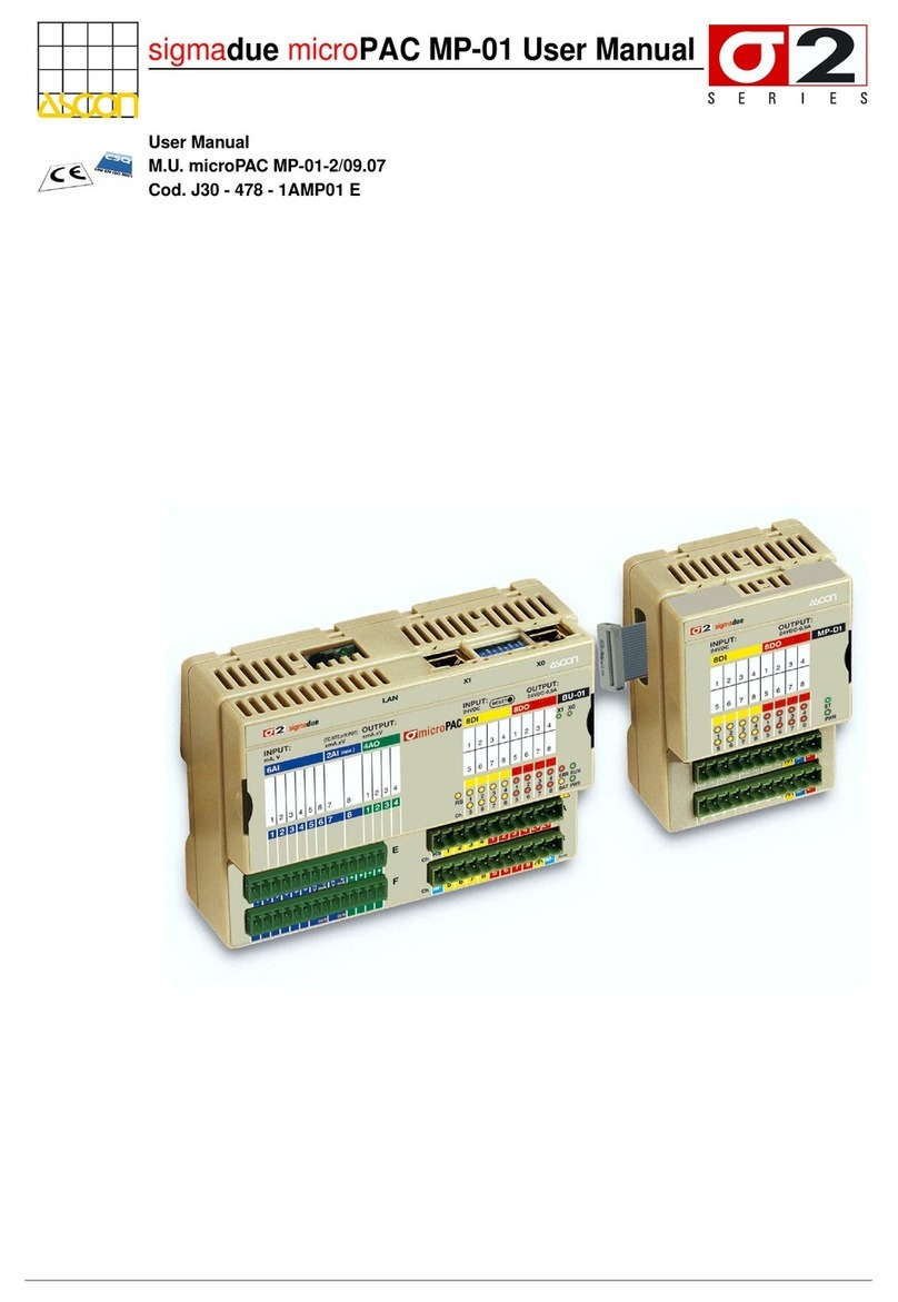
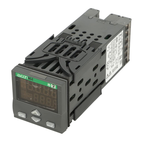
ascon G2 Series User manual

Process Controller
with Setpoint
Programmer
1/16 DIN - 48 x 48
M5 line cc
User Manual • M.I.U.M5-4/03.01 • Cod. J30-478-1AM5 IE
ASCON spa
20021 Bollate
(Milano) Italy
via Falzarego, 9/11
Tel. +39 02 333 371
Fax +39 02 350 4243
http://www.ascon.it
e-mail [email protected]
ASCON spa
ISO 9001
Certified
UL
CUS
LISTED
M5 UK•ed4 10-12-2004 16:20 Pagina 1

Process Controller
with Setpoint
Programmer
1/16 DIN - 48 x 48
M5 line cc
48.50
48.50
1
2
3
REM
SP 1
SP 2
RUN
MAN
A / M
UL
CUS
LISTED
M5 UK•ed4 10-12-2004 16:20 Pagina 1

2
Indications
cc
NOTES
ON ELECTRIC
SAFETY AND
ELECTROMAGNETIC
COMPATIBILITY
Please, read carefully these instructions before proceeding with the instal-
lation of the controller.
Class II instrument, real panel mounting.
This controller has been designed with compliance to:
Regulations on electrical apparatus (appliance, systems and installations)
according to the European Community directive 73/23/EEC amended by the
European Comunity directive 93/68/EEC and the Regulations on the essen-
tial protection requirements in electrical apparatus EN61010-1 : 93 + A2:95.
Regulations on Electromagnetic Compatibility according to the European
Community directive n089/336/EEC, amended by the European Community
directive n° 92/31/EEC, 93/68/EEC, 98/13/EEC
and the following regulations:
Regulations on RF emissions
EN61000-6-4 : 2001 industrial environments
Regulation on RF immunity
EN61000-6-2 : 2001 industrial equipment and system
It is important to understand that it’s responsibility of the installer to ensure
the compliance of the regulations on safety requirements and EMC.
The device has no user serviceable parts and requires special equipment
and specialised engineers. Therefore, a repair can be hardly carried on direct-
ly by the user. For this purpose, the manufacturer provides technical assistance
and the repair service for its Customers.
Please, contact your nearest Agent for further information.
All the information and warnings about safety and electromagnetic com-
patibility are marked with the Bsign, at the side of the note.
M5 UK•ed4 10-12-2004 16:20 Pagina 2

3
Table of Contents
TABLE OF CONTENTS 1INTRODUCTION....................................................................................................................................PAGE 4
1.1 PRODUCT CODING.................................................................................................................PAGE 5
2INSTALLATION ........................................................................................................................................PAGE 6
2.1 DESCRIPTION ...............................................................................................................................PAGE 6
2.2 OPERATING CONDITIONS..................................................................................................PAGE 7
2.3 INSTALLATION...............................................................................................................................PAGE 7
3ELECTRICAL CONNECTIONS.......................................................................................PAGE 8
3.1 TERMINATION UNIT ................................................................................................................PAGE 8
3.2 CABLING LAYOUT....................................................................................................................PAGE 8
3.3 ELECTRICAL CONNECTIONS .......................................................................................PAGE 9
4OPERATIONS.............................................................................................................................................PAGE 15
4.1 FRONT PANEL..............................................................................................................................PAGE 15
4.2 CONFIGURATION .......................................................................................................................PAGE 16
4.3 PARAMETER SETTING.........................................................................................................PAGE 20
4.4 ACCESS LEVELS ........................................................................................................................PAGE 27
5DISPLAYS.........................................................................................................................................................PAGE 29
6COMMANDS...............................................................................................................................................PAGE 30
6.1 COMMANDS FROM KEYBOARD ...............................................................................PAGE 31
6.2 COMMANDS FROM DIGITAL INPUTS ................................................................PAGE 33
6.3 COMMANDS FROM SERIAL COMMUNICATION
(PLEASE, REFER THE ADDENDUM ON THE SERIAL COMMUNICATION)
7SETPOINT PROGRAMMER ( OPTIONAL )..........................................................PAGE 34
7.1 PROGRAM ORGANISATION............................................................................................PAGE 34
7.2 OPERATING CONDITIONS ...............................................................................................PAGE 36
7.3 PROGRAM INPUT AND EDITING ................................................................................PAGE 37
7.4 RUN/STOP OF A PROGRAM........................................................................................PAGE 38
8TECHNICAL SPECIFICATIONS....................................................................................PAGE 39
M5 UK•ed4 10-12-2004 16:20 Pagina 3

4
1 - Introduction
1INTRODUCTION POWERFUL FEATURES AND A WIDE RANGE OF FUNCTIONALITIES
Congratulations for having chosen
these universal controllers. They are the
best result of our experience in design-
ing and manufacturing of smart, pow-
erful and high reliable controllers.
The process controllers of the M5
series have been designed for the
industrial environment, are provided
with a complete set of functions, as
a true universal instrument.
They can be used as Controllers-
Programmers with 1 Setpoint pro-
file of 16 segments.
Main universal input
Two digital inputs
Control Alarms
Retransmission
Resources
OP1PV
AUX
IL1
IL2
OP2
OP3
OP4
(option)
Modbus RS485
Parameterisation
Supervision
(option)
M5
Setpoint
Digital inputs (IL1, IL2) functions
Tuning
One shot
Auto tuning Adaptive
Auxiliary input
(option)
Operating mode
PV/SP
Memory Chip
Data Copy/Data Store
(option)
2Single OP4 OP1 OP2 OP3
action
3Double OP1 OP2 OP3 OP4
action
4Double OP1 OP4 OP2 OP3
action
5Double OP4 OP2 OP1 OP3
action
1Single OP1 OP2 OP3 OP4
action
6Valve OP1 OP2 OP3 OP4
M5 UK•ed4 10-12-2004 16:20 Pagina 4

5
1 - Introduction
1.1 PRODUCT CODING
The complete code is displayed on
the instrument label.
The information about product cod-
ing are accessible from the front panel
by mean of a particular procedure
described at section 5.1 pag 29
Power Supply A
100 - 240V~(- 15% + 10%) 3
24V~(- 25% + 12%) or 24V– (- 15% + 25%) 5
Outputs OP1 (OP2) B
Relay - Relay 1
Relay - Triac 2
Triac - Relay 4
Triac - Triac 5
Serial Comms. C
Not fitted
0
0
0
0
0
0
Options
None [2]
Auxiliary
Input
Feedback potentiometer [2]
Auxiliary
Output SSR drive/analogue + Remote Setpoint [1] [2]
SSR drive/analogue
Current Transformer
Remote Setpoint [1]
D
0
1
2
3
4
5
RS485
Modbus/Jbus
protocol
5
5
Auxiliary
Input 5
Feedback potentiometer [2]
5
5
0
1
None [2]
2
3
Current Transformer
Remote Setpoint [1]
4
SSR drive/analogue auxiliary output
Model:
Power Supply
Outputs
Serial comm.s/Options
–
Line Model Basic Accessories
Colour
Instruction handbook
Setpoint
0M5 A B C D E F G
C DB
3150
Hard
1
2
3
REM
SP 1
SP 2
RUN
MAN
A / M
P/N
CONF
S/N
V~(L-N).85÷264V 50/60 Hz - 3W
; M5-3150-0000
:
: A0A-9809/0011
Basic product code
Instrument label
[1] Not available with Setpoint programmer installed (E = 1)
[2] Second digital input (IL2) not available
Fitted 1
Instruction handbook F
Not fitted
Italian-English (std) 0
0
Setpoint Programmer E
French-English 1
German-English 2
Spanish-English 3
Front panel Colour G
Dark (std) 0
Beige 1
M5 UK•ed4 10-12-2004 16:20 Pagina 5

6
2 - Installation
2INSTALLATION
Installation must only be carried
out by qualified personnel.
Before proceeding with the installation
of this controller, follow the instructions
illustrated in this manual and, partic-
ularly the installation precautions
marked with the Bsymbol, relat-
ed to the European Community direc-
tive on electrical protection and elec-
tromagnetic compatibility.
B
To prevent hands or metal touching
parts that may be electrically live, the
controllers must be installed in an
enclosure and/or in a cubicle.
2.1 INSTALLATION DESCRIPTION
Product code label
Sealing front panel gasket
Mounting Clamps
Front Panel
IP65 protection
EN 60529 (IEC 529)
Panel surface
Memory Chip
connector
IP 20 Termination Unit
EN61010 - 1 (IEC1010 - 1)
2.1.1 DIMENSIONAL DETAILS
48 mm
1.89 in
150 mm
5.9 in
20 mm max
0.79 in max
48 mm
1.89 in
2.1.2 PANEL CUT-OUT
65 mm min
2.56 in min
45+0.6 mm
1.78+0.023 in
45+0.6 mm
1.78+0.023 in
65 mm min
2.56 in min
M5 UK•ed4 10-12-2004 16:20 Pagina 6

7
2 - Installation
2.2 ENVIRONMENTAL RATINGS B
Operating Conditions
MAltitude up to 2000 m
TTemperature 0…50°C
%Rh Relative Humidity 5…95 %Rh non-condensing
Special Conditions
MAltitude > 2000 m
TTemperature >50°C
%Rh Humidity > 95 %Rh
PConducting atmosphere Use filters
Warm up
Use forced air ventilation
Use 24V~supply version
Suggestions
Forbidden Conditions D
CCorrosive atmosphere
EExplosive atmosphere
1
1
1
2
2.3.1 INSERT THE INSTRUMENT
1Prepare panel cut-out
2Check front panel gasket position
3Insert the instrument
through the cut-out
2.3 PANEL MOUNTING [1]
2.3.2 INSTALLATION SECURING
1Fit the mounting clamps
2Push the mounting clamps towards
the panel surface to secure the
instrument
1
3
2
2.3.3 CLAMPS REMOVING
1Insert the screwdriver in the clips
of the clamps
2Rotate the screwdriver
1
2
2.3.4 INSTRUMENT UNPLUGGING
B
1Push and
2Pull to remove the instrument
Electrostatic discharges can damage
the instrument
Before removing the instrument the
operator must discharge
himself to ground
1
2
1
1MΩ
UL note
[1] For Use on a Flat Surface of a Type 2 and Type 3 ‘raintight’ Enclosure.
M5 UK•ed4 10-12-2004 16:20 Pagina 7

8
3 - Electrical Connections
3ELECTRICAL
CONNECTIONS
PRECAUTIONS
B
Despite the fact that the instrument
has been designed to work in an
harsh and noisy environmental (level
IV of the industrial standard IEC 801-
4), it is strongly recommended to fol-
low the following suggestions.
A
All the wiring must comply with the
local regulations.
The supply wiring should be routed
away from the power cables.
Avoid to use electromagnetic con-
tactors, power relays and high power
motors nearby.
Avoid power units nearby, especially
if controlled in phase angle
Keep the low level sensor input wires
away from the power lines and the
output cables.
If this is not achievable, use shielded
cables on the sensor input, with the
shield connected to earth.
UL note
[1] Use 60/70 °C copper (Cu) conduc-
tor only.
3.1 TERMINATION UNIT [1] B3.2 RECOMMENDED ROUTING OF WIRES B
0,5
Nm
6
5
4
3
2
1
12
11
10
9
8
7
18
17
16
15
14
13
Rear
terminal
covers
Wire size
1 mm2
(18 AWG
Solid/Stranded)
5.7 mm
0.22 in
6
5
4
3
2
1
12
11
10
9
8
7
18
17
16
15
14
13
6
5
4
3
2
1
12
11
10
9
8
7
18
17
16
15
14
13
Conduit for supply and output cables
Conduit for low level sensor cables
A
L
N
BB
CDE
A
L
N
BB
CDE
A= Supply
B= Relay/Triac Output
C= Analog Inputs
D= Serial
Communication
E= Auxiliary
Inputs/Outputs
F= Digital Inputs
FF
18 screw terminals
Option terminals
Holding screw 0.5 Nm
Positive screw
driver PH1
Negative screw
driver 0,8 x 4 mm
Terminals
Pin connector q1.4 mm
0.055 in max
Ø
Fork-shape AMP 165004
Ø 5.5 mm - 0.21 in
L
Stripped wire
L 5.5 mm - 0.21 in
M5 UK•ed4 10-12-2004 16:20 Pagina 8

9
3 - Electrical Connections
3.3 TYPICAL INSTRUMENT WIRING (valve control) B
Supervisory
RS485
6
OP1
V~
18V–
5
4
3
2
1
12
11
10
9
8
7
18
17
16
15
14
13
PTC
OP2
OP3 Supply V ~
L
N
L
N
PV
mA mV-V Tc Pt100
A
B
B
2 wires
transmitter
C
Alarm
V~
Fuse
2A ~T
[6]
V~
Fuse
Fuse
[6]
[6]
Digital
Input
PLC
Commands
Power switch
M
Positioner module
Buffer
relays
Raise
Lower
6
5
4
12
11
10
9
18
17
16
15
14
13
C
RS485
DIGITAL INPUT
mA V
18 V—
OUT
OP3
OP4
(REM)
N
L
NO
C
TC
CT
OP2
NO
C
NO
[5]
[5]
71
82
3
12
11
10
RTD POT
100%
0%
OP1
1
2
A
b
B
Option terminals
Notes:
1] Make sure that the power supply volt-
age is the same indicated on the
instrument.
2] Switch on the power supply only after
that all the electrical connections have
been completed.
3] In accordance with the safety regu-
lations, the power supply switch shall
bring the identification of the relevant
instrument. The power supply switch
shall be easily accessible from the
operator.
4] The instrument is PTC protected. In
case of failure it is suggested to return
the instrument to the manufacturer for
repair.
5] To protect the instrument internal cir-
cuits use:
- 2 A~T fuses for Relay outputs
- 1 A~T fuses for Triac outputs
6] Relay contacts are already protected
with varistors.
Only in case of 24 V ~inductive
loads, use model A51-065-30D7
varistors (on request)
M5 UK•ed4 10-12-2004 16:20 Pagina 9

10
3 - Electrical Connections
3.3.1 POWER SUPPLY B
Switching power supply with multiple
isolation and internal fuse
• Standard version:
nominal voltage:
100 - 240V~(-15% + 10%)
Frequency 50/60Hz
• Low Voltage version:
Nominal voltage:
24V~(-25% + 12%)
Frequency 50/60Hz
or 24V– (-15% + 25%)
• Power consumption 3Wmax
3.3.2 PV CONTROL INPUT B
A For J L T K S R thermocouple type
• Use always compensation cable of
the correct type for the thermo-
couple used
• Use always compensation cable of
the correct type for the thermo-
couple used
• The shield, if present, must be con-
nected to a proper earth.
B For PT100 resistance
thermometer
• If a 3 wire system is used, use
always cables of the same diame-
ter (1mm2min).
Maximum resistance/line 20 Ω
• If a 2 wire system is used, use
always cables of the same diame-
ter (1.5mm2min).
AWhen the distance between the
controller and the sensor is 15
meters, using a cable of 1.5mm2
diameter, produces an error in the
measure of 1°C .
B1 For ∆T (2x Pt100)
• Use wires of the same length.
Maximum resistance/line 20 Ω.
R1 + R2 must be <320Ω
6
5
150Ω/lead maximum
14
13
included PTC
L
N
6
5
4
A
b
B
When using a 2 wire
system, put a jumper
between terminals 5 and 6
6
5
4
A
B
A
R1
R2
M5 UK•ed4 10-12-2004 16:20 Pagina 10

11
3 - Electrical Connections
3.3.2 PV CONTROL INPUTS (cont.) B3.3.3 AUXILIARY INPUTS (OPTION) B
C For DC input
Input resistance = 30Ωfor mA
Input resistance = 10MΩfor mV
Input resistance = 10KΩfor Volt
A For current transformer CT
for the measure of the load current
• Primary coil 10A…100A
• Secondary coil 50 mA default
100mA jumper selectable
C1 For 2 wires transmitters
• Power supply to the transmitter
18V– ±10%
30mA max
Input resistance = 30Ω
C2 For 3 or 4 wires transmitters
• Power supply to the transmitter
18V– ±10%
30mA max
Input resistance = 30Ω
6
5
mA mV-V
Rj
6
5
Rj
18V–
3
PV
Transmitters
mA
6
5
Rj
18V–
3
PV
mA
Transmitters
12
11
10…100A50/100mA
load
CT
~
5 watt burden resistor
0.5Ωfor 1A secondary
transformer coil
0.1Ωfor 5A secondary
transformer coil
Option Module
for CT
Jumper for
100 mA
secondary
transformer coil
M5 UK•ed4 10-12-2004 16:20 Pagina 11

12
3 - Electrical Connections
3.3.5 OP1 OP2 OP3 AND OP4 OUTPUTS B
The functionality associated to each of the OP1 OP2 OP3 and OP4 outputs
is defined during the configuration of the instrument.
The possible choices are:
Note
[1] In case of OP4 analogue output, its status is not visualised by any red led
[2] When the OP4 SSR drive output is selected, the status of OP1 and OP2, as alarms,
is not displayed by any red led
where:
3.3.4 DIGITAL INPUTS B
• The associated function is active
when the digital input is ON
(see table on page 33)
• The second digital input (IL2) is
available only with the following
options:
Remote Setpoint (D = 2)
Current transformer (D = 3)
SSR drive / analogue output (D = 4)
OP1 - OP2
OP4
Relay or Triac output
Analogue output
Analogue or SSR drive output
OP4-C
9
10
15
TTL
open collector
NPN
open collector
Isolated
contact
Com.
IL 2
IL 1
C1
C2
C From Position Potentiometer
To read the real position of the motor
or the valve
12
11
10
100%
0%
Total
travel
distance
Operating
Travel
distance
pot.h
pot.I
0%
100% From 100Ωto 10KΩmax
3.3.3 AUXILIARY INPUTS (cont.) B
B From Remote Setpoint
Current
0/4…20mA
Input resistance = 30Ω
Voltage
1…5V, 0…5V, 0…10V
Input resistence = 300KΩ
eIf the analogue input is provided, the
terminals for the Remote Setpoint
are 10(+) and 9(-)
12
11
mAmV-V
Rj
OP3 Relay output
Alarms
OP1
Raise
Retransm.
OP1
Heat OP2 OP3 OP4-C
OP4
Heat OP1 OP2 OP3
OP1
Heat
OP2
Cool OP3 OP4-C
OP1
Heat
OP4 [1]
Cool
OP2
[2] OP3
OP4 [1]
Heat
OP2
Cool
OP1
[2] OP3
PV-SP
OP2
Lower OP3 OP4-C
Valve
Double
action
Double
action
Double
action
Single
action
Single
action
Control
6
5
4
3
2
1
M5 UK•ed4 10-12-2004 16:20 Pagina 12

13
3 - Electrical Connections
3.3.5-A SINGLE RELAY
OUTPUT (TRIAC) B
3.3.5-B SINGLE SSR DRIVE
OUTPUT (OPTION) B
OP1
17
16
V~
Load
OP4
12
11 Load
V~
OP1
18
17
16
OP2 Cool
Load
Load
Heat
V~
3.3.5-C SINGLE ANALOGUE
OUTPUT (OPTION) B
3.3.5-E HEAT COOL OUTPUT RELAY/RELAY (TRIAC/TRIAC) B
3.3.5-F HEAT COOL OUTPUT RELAY (TRIAC)/SSR DRIVE (OPTION)
B
3.3.5-H HEAT COOL OUTPUT RELAY(TRIAC)/ANALOGUE (OPTION)
B
3.3.5-G HEAT COOL OUTPUT SSR DRIVE (OPTION)/RELAY (TRIAC)
B
3.3.5-D VALVE OUTPUT
B
mA
12
11
Load
mV,V
OP1
17
16
V~
Load
Heat
OP4
12
11
LoadCool
mA mV,V
OP4
12
11 Load
V~
Heat
OP2
18
17
V~
Load
Cool
OP1
18
17
16
OP2
V~
Lower
Raise
M
~
OP1
17
16
V~
Load
Heat
OP4
12
11 Load
V~
Cool
1 NO contact
2 NO contacts
Output 0…22V–±20% (20mA max)
galvanic isolated
galvanic isolated
500 V~/ 1min
750Ω/ 15V max if current output
500Ω/ 20mA max if voltage output
3 pole output with NO contacts
(raise, lower, stop)
M5 UK•ed4 10-12-2004 16:20 Pagina 13

14
3 - Electrical Connections
3.3.5-I HEAT COOL OUTPUT DC (OPTION)/RELAY (TRIAC) B
3.3.6 ALARM OUTPUTS OP1, OP2, OP3 B
3.3.7 RETRANSMISSION OUTPUT (OPTION) B
3.3.8 SERIAL COMMUNICATION (OPTION) B
OP4
12
11
LoadHeat
mA mV,V
OP2
18
17
V~
Load
Cool
OP1
18
17
16
OP2
Load
Load
V~
2
1
V~
Load
OP3
mA
12
11
Load
mV,V
9
8
7
Common
Ground
2 NO contacts
1 NO contact
galvanic isolated
500 V~/ 1min
750Ω/ 15V max if current output
500Ω/ 20mA max if voltage output
eThe analogue/SSR drive output OP4
can be used for signal retransmis-
sion only if it is not used as control
output.
eThe relay/triac output OP1, OP2 and
OP3, can be used as alarm outputs
only if they are not used as control
outputs.
• Galvanic isolation 500V~/1 min
Compliance to the EIA RS485 stan-
dard for Modbus/Jbus
APlease, read:
gammadue® and deltadue®con-
troller series serial communication
and configuration
M5 UK•ed4 10-12-2004 16:20 Pagina 14

15
4 - Operation
4OPERATION
274.8
275.0
1
2
3
REM
SP 1
SP 2
RUN
MAN
A / M
Setpoint
setting Run/stop
of a program
5 Status LED’s (green):
REM - Remote setpoint active
SP1 - first stored setpoint active
SP2 - second stored setpoint active
RUN - program running
MAN - manual operating mode
Output status
LED’s
(reds):
OP1 output ON
OP2 output ON
OP3 output ON
Automatic/
manual
Menu
access Entry key for
selection and
value setting
confirmation
PV measure
in engineering units
Operating
Setpoint
(local/remote
or stored)
Parameter
setting
Entry key for
selection and
value setting
confirmation
Access to the menu for:
- configuration
- parameter setting
- access definition
Parameter value
Parameter mnemonic
35.0
p.b.
1
2
3
REM
SP 1
SP 2
RUN
MAN
A / M
4.1.A KEYS FUNCTION AND DISPLAY IN OPERATOR MODE
4.1.B KEYS FUNCTION AND DISPLAY IN PROGRAMMING MODE
4.1.1 NUMERIC ENTRY
(i.e. the modification of the value of a stored
Setpoint from 275.0 to 240.0)
4.1.2 MNEMONIC SETTING
(Way to modified configuration page 16 / 18)
Press $or %momentarily to
change the value of 1 unit every push.
Continued pressing of $or %
changes the value, at rate that dou-
bles every second. Releasing the but-
ton the rate of change decreases.
In any case the change of the value
stops when it has reached the max/min
limit set for the parameter.
s.p. 2
1253
s.p. 2
1100
s.p. 2
1350
Unit.
°C
Unit
°f
Unit
MA
Unit
ph
Press the $or %to display the
next or previous mnemonic for the select-
ed parameter. Continued pressing of
$or %will display further mnemon-
ics at a rate of one mnemonic every 0.5
seconds. The mnemonic displayed at the
time the next parameter is selected, is
the one stored in the parameter.
2nd stored
Setpoint
2nd stored
Setpoint
2nd stored
Setpoint
Centigrade Degrees
Engineering Units
Fahrenheit Degrees
Engineering Units
mA
Engineering Units
Ph
Engineering units
—lower
—raise
The new value is
entered when the next
parameter is selected
by mean of the R
key.
M5 UK•ed4 10-12-2004 16:20 Pagina 15

16
4 - Operation
4.2 CONFIGURATION PROCEDURE
Conf
Inp.
sC.dd
sc.lo
sc.Hi
sqr
CHar
Conf
rs.p.C
rs.In
C.pas
275.8 Menu
Unit
Inp
s.p.tM
s.p.
33
274.8 Conf
OK
é0=10
é 0
é 0
é9999
éno
éno
énone
éLoc
é4=20
éP:Sec
Input type
see table 1
N° of decimals
(linear input only)
0/ 1/2/ 3
Low range
(linear input only)
from min range up to
sc.Hi
High range
(linear input only)
from sc.lo to max
range
Square root
(linear input only)
no / yes
Linear inputs
characterisation
no / yes
Engineering Units
see table 2
Inputs
Configuration
Operator
Mode
Press the key until
YES
Enter the configuration
password
NO
Configuration
menu
Setpoint
Configuration
Setpoint selection
see Table 3
Remote Setpoint input
(remote input only)
see Table 4
Time units
and Setpoint slope
p.sec/ p.Min /.phr
Back to the
1st parameter
inp.=Conf
Back to the
1st parameter
s.p.=Conf
If the entered password
corresponds to the value set in
the parameter C.pas at pag. 27,
proceed to YES
from -999 to 9999
(33 as default from the factory)
If the configured hardware option is not installed, the display shows an
hardware error message
H.Err
100
100 Analog output not installed
101 Current trasformer not installed
102 Remote Setpoint input not installed
103 Potentiometer input not installed
104 Analogue output + Remote Setpoint not installed
M5 UK•ed4 10-12-2004 16:20 Pagina 16

17
4 - Operation
ConfConf
O.Ity
H.C.OP
s.Out
rtH
Conf
Il1 Al.1
AI.Ou
ltch
bloc
Al.2
A2.Ou
ltch
Al.3
A3.Ou
ltch
bloc
Al.4
A4.Ou
Il2
bloc
Out L.inP AlM
ltch
C.C.OP
O.r.ty
rt.lo
rt.Hi
éPid:r
éOFF
éOFF
énone
é4=20
é0
é9999
éOFF
éOFF
éOFF
éOFF
éOP1
éno
éno
éOFF
éOP1
éno
éno
éOFF
éOP1
éno
éno
éOFF
éOP1
éno
CONFIGURATION MENU
Output
Configuration
Digital inputs
configuration
Alarm s
configuration
Type of Control
see Table 5
Heat control output
see Table 6
Control output
safety value
Off/ -100…100%
Retransmission output
(available for DC output
only)
none / pU / s.p.
Retransmission output
type
(available for DC output only)
see Table 4
Retransmission
low range
whole range
Retransmission
high range
whole range
Cool control output
see Table 7
AL1 alarm type
see Table 9
AL1 addressing
(not available when AL1 is
OFF)
OpI / Op2/ Op3
AL1 latching
(not available when AL1 is
OFF)
no / yes
AL1 start-up disabling
(not available when AL1 is
OFF)
no / yes
AL2 alarm type
see Table 9
AL2 addressing
(not available when AL2 is
OFF)
OpI / Op2/ Op3
AL2 latching
(not available when AL2 is
OFF)
no / yes
AL2 start-up disabling
(not available when AL2 is
OFF)
no / yes
AL3 alarm type
see Table 9
AL3 addressing
(not available when AL3 is
OFF)
OpI / Op2/ Op3
AL3 latching
(not available when AL3 is
OFF)
no / yes
AL3 start-up disabling
(not available when AL3 is
OFF)
no / yes
AL4 alarm type
see Table 9
AL4 addressing
(not available when AL4 is
OFF)
OpI / Op2/ Op3
AL4 latching
(not available when AL4 is
OFF)
no / yes
AL4 start-up disabling
(not available when AL4 is
OFF)
no / yes
Back to the 1st parameter of Out=Conf
IL1 function
see Table 8
IL2 function
see Table 8
Back to the
1st parameter of
L.inp=Conf
M5 UK•ed4 10-12-2004 16:20 Pagina 17

Value
Description
18
4 - Operation
Conf
EHit
Ht.f.C
Ht.on
bloc
éno
é100
éOFF
Output
Configuration
CT High range
(available if at least one
alarm is Htr)
10…100
CT decimal point
(available if at least one
alarm is Htr)
Off / On
Back
to operator mode
Back to the
1st parameter
AlM=Conf
Tab. 4
Value Description
0=5 0…5 Volt
1=5 1…5 Volt
0=20 0…20 mA
4=20 4…20 mA
Tab. 5 Control type
Of.re Reverse action On - Off
Of.di Direct action
pid.d Direct action P.I.D.
pid.r Reverse action
U.dir Direct action Modulating
valves
U.reU Reverse action
H.C.ln Linear Heat/
Cool
H.C.Ol Oil charac.
H.C.H2 Water charac.
Tab. 6 Heat control output
Value Description éH.C.OP
Off Not used
rI Relay 1 Digital signal
log SSR drive
0=5 0…5 Volt
Analogue
signal
1=5 1…5 Volt
0=10 0…10 Volt
0=20 0…20 mA
4=20 4…20 mA
Rem. Setpoint
Value Description éOI.ty
Tab. 7 Cool control output
Value Description ééC.C.OP
Off not used
r2 relay 2 Digital signal
log SSR drive
0=5 0…5 Volt
Analogue
signal
1=5 1…5 Volt
0=10 0…10 Volt
0=20 0…20 mA
4=20 4…20 mA
Tab. 8 Digital Inputs function
éIl1
Value éIl2
Off Not used
l=r Local/remote
A.Man Auto/manual
s.p.1 1st stored Setpoint
s.p.2 2nd stored Setpoint
keb.I Keypad
slo.1 s.p. slope disable
H.pU Measure hold
r.=H.Run/stop of a program
Tab. 9 Alarm type
éAl1 éAl2
Off Not used
fs.H Active high Absolute
fs.l Active low
deU.H Active high Deviation
deU.l Active low
band Out active
Htr Active high
lba Loop break alarm (Al1 only)
Heater Break
Band
Tab. 1 Input type
éInp.
Value
Value
tc.j 0…600°C
Description
tc.l
éUnit
tc.K
tc.s
Tab. 2 Engineering units
none None
°C Centigrade Degrees
°f Fahrenheit Degrees
MA mA
MU mV
UVolt
bar bar
psI PSI
0=10
MU
tc.t
tc.r
rtd1
cuSt
1=5
0=5
rtd2
del.t
4=20
0=20
rh Rh
ph Ph
Tab. 3 Setpoint type
reM.t Remote - trim
loc.t Local - trim
l=r Local/remote only
reM Remote only
loc Local only
Value Description érs.p.C.
éAl3 éAl4
Description
Description
32…1112°F
4…20 mA
0…20 mA
0…10 Volt
1…5 Volt
0…5 Volt
0…50 mV
-50.0…50.0°C
-99.9...300.0°C
-200…600°C
Custom range on request
-200…400°C
0…1600°C
0…1600°C
0…1200°C
0…600°C
Engineering
units
-58.0…122.0°F
-99.9…572.0°F
-328…1112°F
-328…752°F
32…2912°F
32…2912°F
32…2192°F
32…1112°F
0=10 0…10 Volt
érs.In
Retransmission éO.r.ty
M5 UK•ed4 10-12-2004 16:20 Pagina 18

19
4 - Operation
It is possible to configure up to 4 alarms:
AL1, AL2, AL3, AL4 (see pag. 17), select-
ing, for each of them:
Athe type and the operating condition of
the alarm
(table 9 page 18)
Bthe functionality of the alarm acknowl-
edgement (latching) àltch
Cthe start-up disabling (blocking) àbloc
Dthe physical output of the alarm
àOpI àOp2 àOp3
The outputs can be used for alarms if
they are not used as control outputs
(see par. 3.3.5 page12)
It is possible to route up to 4 alarm to a sin-
gle output (OR of the alarms).
Alarm occurrence display
This function can be enabled by the
configuration software.
(please read the user instruction on
the "M5 LINE MODBUS /JBUS PRO-
TOCOL", supplied separately)
The range of the alarm threshold corre-
spond to the whole span and it is not lim-
ited by the SP Setpoint span.
[A] OPERATING CONDITIONS
4.2.1 AL1, AL2, AL3, AL4 ALARMS CONFIGURATION
[B] ALARM ACKNOWLEDGE
FUNCTION
The alarm, once occurred, is presented on
the display until to the time of acknowl-
edge. The acknowledge operation consists
in pressing any key.
After this operation, the alarm leaves the
alarm state only when the alarm condition
is no longer present.
ltch
yes
[C] START-UP DISABLING
[D] LOOP BREAK ALARM LBA
When the controller connection to the sen-
sor is discontinued or other faults are
detected in the control loop, the AL1 alarm
becomes active, after a predefined time of
1 to 9999 s, from the detection of the fail-
ure.
The alarm state ceases when the fault con-
dition is no longer present.
275.0
1
2
32f.5.H
The red led of the activated alarm output
is on.
The type of alarm is presented
flashing, on the front panel in
alternation with the PV value.
eIn case of ON-OFF control, the LBA
alarm is not active.
275.0
A / M
1
2
3Ilba
mA
°C
OP1
∆SP Disable
SP
On
Off
Start-up
ramp
down
ramp
up
∆SP
Threshold
=
SP ±range
SP
∆SP
On
Off
Disable
Start-up
Absolute alarm
active high
é-fsH
active low
é-fsl
hyd hyu
On
Off
On
Off
Alarm thresholdhigh rangelow range
Deviation alarm
active high
active low
é-del
hyd hyu
On
Off
On
Off
SP
Alarm threshold + range- range
é-deH
Band alarm
active out
é-bnd
hyd hyu
On
Off
SP
Alarm threshold
full scale
full scale
hyd hyu
∆SP
∆SP ∆SP
bloc
yes
M5 UK•ed4 10-12-2004 16:20 Pagina 19
This manual suits for next models
1
Table of contents
Other ascon Controllers manuals

ascon
ascon e33 User manual

ascon
ascon XE Series User manual

ascon
ascon Z31 User manual

ascon
ascon K31D User manual

ascon
ascon KX6 Installation and operation manual

ascon
ascon TLK72 B User manual

ascon
ascon X34S User manual

ascon
ascon M4 series User manual

ascon
ascon S2 Series User manual

ascon
ascon QP Series User manual