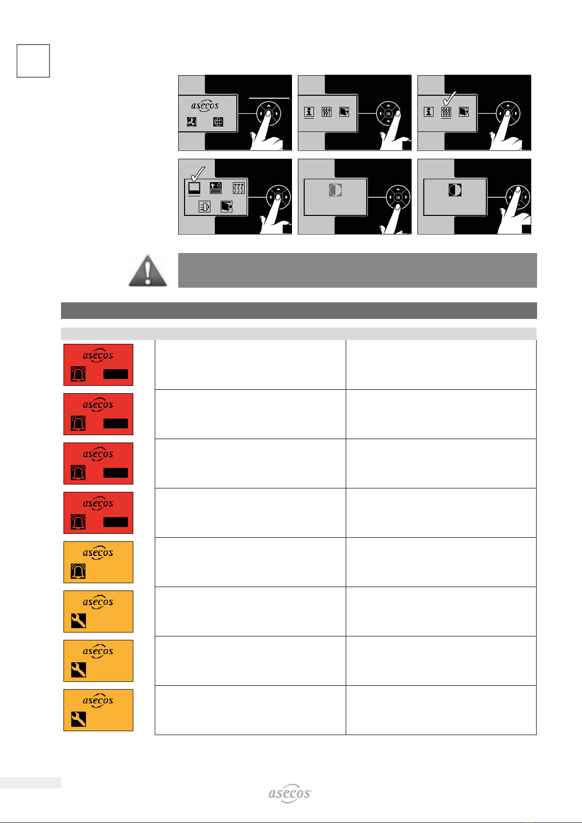
asecos UFA.025.030 User manual

EN
EP.V.34660.01 | 05/2022
USER MANUAL
Recirculating air filter unit
UFA.025.030(.XL)

2
EN
1. NOTES • GUIDELINES • GUARANTEE ............................................. 3
1.1. General safety notes ............................................ 3
1.2. Guarantee ..................................................... 3
1.3. Development and Manufacturer ................................... 3
1.4. Purpose of use ................................................. 3
2. CONSTRUCTION AND FUNCTION. . . . . . . . . . . . . . . . . . . . . . . . . . . . . . . . . . . . . . . . . . . . . . . . 4
2.1. Material ....................................................... 4
2.2. Accessories .................................................... 4
2.3. Mode of operation .............................................. 4
2.4. Ventilation setting / monitoring ................................... 4
2.5. Potential-free alarm contact ...................................... 5
3. ERECTION • COMMISSIONING .................................................. 5
3.1. Commissioning................................................. 5
3.2. Self-test....................................................... 6
4. DISPLAY AND MENU .......................................................... 6
4.1. Power indicator ................................................ 6
4.2. Overview of the menu icons ...................................... 7
4.3. Show system information ........................................ 7
4.4. Set display contrast ............................................. 8
5. MALFUNCTIONS • ACTIONS .................................................... 8
6. REPAIRS .................................................................... 9
7. FUNCTIONAL CHECK • MAINTENANCE • CARE ..................................... 9
7.1. Sensors and monitoring electronics ................................ 9
7.2. Cleaning ...................................................... 9
8. TECHNICAL DATA............................................................ 10
9. TECHNICAL DRAWING........................................................ 10
10. ATEX MARKING ..............................................................11

3
EN
1. NOTES • GUIDELINES • GUARANTEE
1.1. GENERAL SAFETY NOTES
• Observe applicable statutes and regulations, and the notes in these operating instructions, when handling
hazardous materials
• Only use the recirculation filter attachment when it is in proper condition
• Please follow the instructions of the safety experts, technical supervisory services (BG, GAA, pharmacy equip-
ment) of the construction supervision, etc.
• Observe accident prevention regulations and workplace ordinance
• Check the recirculation filter attachment regularly for proper function (exhaust air volume flow and filter satura-
tion by checking the indicators)
1.2. GUARANTEE
The guarantee for this product is agreed between you (the customer) and your dealer (the seller). As the
manufacturer, asecos guarantees the products listed in the operating instructions for a period of 24 months
from the date of delivery. All model safety equipment are subject to a compulsory annual inspection by spe-
cialised sta authorised by the manufacturer. Otherwise the customer’s guarantee claim against the manufac-
turer expires.
1.3. DEVELOPMENT AND MANUFACTURER
asecos GmbH, Weiherfeldsiedlung 16-18, 63584 Gründau, Germany
The type plate with the serial number is located on the outside of the unit’s housing
1.4. PURPOSE OF USE
The unit is used for technical ventilation from Ex zone 2 or no Ex zone of safety cabinets used for storing flam-
mable liquids. The recirculation filter attachment is particularly low-noise and therefore ideal for use directly in
the working environment.
Suitable for cabinet models:
UFA Model Suitable cabinet groups
UFA.025.030 S-LINE / Q-LINE / V-LINE / UB-LINE / CS.195.105.F / E.195.105.F
UFA.025.030.XL XL-LINE / S-CLASSIC-30
Set-up requirements
OK
OK OK OK
CAUTION:
The unit may only be installed in a non-hazardous area!
The integrated activated carbon filter removes 99.999% of the hydrocarbons from the exhaust air so that
it can be discharged directly into the room air. The pollutant-containing exhaust air stream does not come
into contact with electrical current-carrying components. The unit is therefore suitable for exhausting
cabinets that are defined in EN 14470 Part 1 or DIN 12925 Part 1. An exhaust duct leading to the outside
at a non-hazardous location can therefore be omitted. A CE certificate of conformity (also according to EC
Directive 2014/34/EU - ATEX Directive) is available.

4
EN 2. CONSTRUCTION AND FUNCTION
2.1. MATERIAL
RAL
7035
RAL
7016
OK
INFO:
The housing is made of powder-coated fine sheet steel
2.2. ACCESSORIES
• Activated carbon main filter incl. suspended matter pre-filter (order no. 40201), housing ABS/galvanised sheet
steel, filling activated carbon (approx. 3500 gr).
• Secondary filter (order no. 40202), ABS housing, ABEK activated carbon filling (140 g) incl. suspended matter
prefilter
2.3. MODE OF OPERATION
Fresh air
activated carbon filter
gases and vapours in
cabinet
CAUTION:
Filter can only retain
solvent vapours
(hydrocarbons). Please
consult us if other
materials are to be
stored.
Safe and faultless
function is shown by
the ventilation and filter
monitoring mechanism
which is fitted as
standard. (3.2)
ventilator
2.4. VENTILATION SETTING / MONITORING
The performance of the fan is sucient to achieve an air exchange rate of at least 10 times for the cabinet
models listed under point 1.3. The proper ventilation function is independently controlled by an electronic
monitoring system. The air volumes are monitored in the exhaust air shaft by means of pressure dierential
measurement. An optical and acoustic alarm is triggered when the air exchange rate falls below the set value.
The visual alarm only goes out when the setpoint is reached again, the acoustic alarm can be cancelled by
pressing the “OK button” be interrupted.

5
EN
2.5. POTENTIALFREE ALARM CONTACT
To use the potential-free alarm contact, the three-pole plug supplied must be used. The contact is designed
for a maximum direct voltage of DC 30 V or an alternating voltage of AC 230 V. The maximum current carry-
ing capacity is 10 A.
The plug is connected according to the following diagram:
L
2
1
11
1214
Internal alarm contact Connector External connection
Contact position
Normal operation: "L" and "1"
are connected
Alarm or mains failure: "L"
and "2" are connected
CAUTION:
The potential-free alarm contact must not be used to switch large loads. It is only intended to signal a
malfunction of the recirculation filter attachment by means of a signal light, horn or similar.
The connection must be carried out by a qualified electrician!
3. ERECTION • COMMISSIONING
3.1. COMMISSIONING
123
4
230 V
5
OK
6
ATTENTION:
Observe the instructions point 1.4 Intended use

6
EN 3.2. SELFTEST
12
OK
3
O
4
OK
5
OK
ok ok
6
ATTENTION:
The unit is designed for continuous operation!
PLEASE NOTE:
As soon as the unit is connected to the mains, a self-test begins during which all safety-relevant compo-
nents are checked. If there is a fault, the unit will not start. An error F7 is displayed alternating with the
relevant faulty safety element F1-F4.
4. DISPLAY AND MENU
4.1. POWER INDICATOR
OK
ok ok
Control element with arrow
keys and OK key
Display including error indication
IN THE EVENT OF A MALFUNCTION:
Measures see 6. malfunctions

7
EN
4.2. OVERVIEW OF THE MENU ICONS
Symbols in the active screen
Volume flow OK Filter saturation OK
Symbols in the main menu
Information Settings submenu Exit current display
Symbols in the Settings menu and sub-items
Set contrast Carry out filter change Set air monitoring
parameters
Replace sensor Exit current display
4.3. SHOW SYSTEM INFORMATION
ATTENTION:
For a simplified service procedure, please have the system information ready.
> 5Sec
1
1.
2
3
NOTE
The system automatically switches to the normal display when there is no activity or no input.

8
EN 4.4. SET DISPLAY CONTRAST
>
5
Sec
1
1.
2
1.
3
4
5
6
NOTE
The system automatically switches to the normal display when there is no activity or no input.
5. MALFUNCTIONS • ACTIONS
Malfunction Problem - Measure Note - be sure to observe!
AL 1AL 1
Pressure dierence across the filter too low.
(Fan defective or air outlet blocked).
Please check the air outlet.
Please contact your specialist dealeror our service hotline 01805 - 92
20 92
AL 1AL 2
Pressure dierence over the filter too high.
(filter too dirty, air flow rate too low).
Main filter change necessary!
Please contact your specialist dealer or our service hotline 01805 - 92
20 92.
AL 1AL 3
The filter is almost completely saturated,
a timely change is necessary.
Attention: Possible accident inside the cabinet! Eliminate
leakage professionally and change filter!
Please contact your specialist dealer or our service hotline 01805 - 92
20 92
AL 1AL 4
The filter is completely saturated and the fan has been
switched o.
It is now imperative to change the filter at short notice.
Main filter and secondary filter change necessary!
Please contact your specialist dealer or our service hotline 01805 - 92
20 92
1
W
The filter is close to its saturation limit,
a timely change is imperative.
Please contact your responsible specialist dealer
or to our service hotline 01805 - 92 20 9
Ser 1
Filter runtime longer than 8040 operating hours (11 months)
The permissible operating time of the filter has almost expired.The filter
must now be changed at short notice.
Please contact your responsible specialist dealer
or to our service hotline 01805 - 92 20 9
Ser 2
Filter runtime longer than 8760 operating hours (12 months)
The permissible operating time of the filter has expired. The filter must
now be changed at short notice.
Please contact your responsible specialist dealer
or to our service hotline 01805 - 92 20 9
Ser 3
Filter sensor runtime longer than 48 months
A sensor replacement should be carried out in the course of the next
safety inspection.
Please contact your responsible specialist dealer
or to our service hotline 01805 - 92 20 9

9
EN
Ser 4
Running time of the filter sensor longer than 54 months.
Sensor drift and thus safe operation can no longer be guaranteed. The
sensor must be replaced.
Please contact your responsible specialist dealer
or to our service hotline 01805 - 92 20 9
F 1
Dierential pressure sensor error Please contact your responsible specialist dealer
or to our service hotline 01805 - 92 20 9
F 2
Error temperature/humidity sensor Please contact your responsible specialist dealer
or to our service hotline 01805 - 92 20 9
F 3
Filter sensor defective Please contact your responsible specialist dealer
or to our service hotline 01805 - 92 20 9
F 4
Fan defective (blocked) Please contact your responsible specialist dealer
or to our service hotline 01805 - 92 20 9
F 7
Self test error
Display F7 alternating with the respective error F1 to F4
Please contact your responsible specialist dealer
or to our service hotline 01805 - 92 20 9
14 ct/called minute from the Deutsche Telekom AG fixed network, from mobile phones a maximum of 42 ct/minute.
6. REPAIRS
ATTENTION
Repairs are only to be carried out by specialists specifically trained for this.
Given damage the appliance is to be repaired or replaced by the manufacturer.
7. FUNCTIONAL CHECK • MAINTENANCE • CARE
To ensure safety, the recirculation filter attachment should be serviced at least once a year and its function
checked by a specialist. At the same time, the built-in filter unit must be replaced at least once a year, and
immediately when the saturation limit is reached.
The functionality is checked electronically by the integrated ventilation and filter saturation monitoring, so that
a function check of the recirculation filter attachment is carried out permanently during operation. The activat-
ed charcoal main filter of the recirculation filter attachment must be replaced with a new filter at short notice
if the corresponding maintenance indicator (red screen) is shown. The filter can only be replaced by one of
our trained service technicians and must be requested promptly on the service hotline. Filter replacement by
asecos service personnel ensures that the contaminated activated carbon is fed into a defined disposal chain.
7.1. SENSORS AND MONITORING ELECTRONICS
The UFA contains sensitive sensors and complex monitoring electronics. The device must be designed as a
“continuous 24/7" and was also designed for this purpose. The sensitive gas sensor system in particular is
heavily stressed by continuous operation and, according to experience, can deliver unreliable measurement
results after a certain period of operation (drift) after approx. 40,000 operating hours.
The UFA can then no longer be used safely (possible monitoring errors).
In this case, a visual warning is given. In this case, please contact the customer service for replacement of the
sensor unit.
7.2. CLEANING
For external cleaning of the recirculating air filter attachment, please use common, mild household cleaners
and a soft cloth. Disconnect your recirculating air filter attachment from the mains by unplugging
the power cable before cleaning! Make sure that no moisture gets into the inside of the recircu-
lating air filter attachment during cleaning.
CONTACT:
In the case of defects or complaints about our products (within and also after the warranty period), and for
requesting safety checks or taking out a service contract, please contact our service hotline on:
Tel: +44 1785 22 70-90 info@asecos.co.uk

10
EN 8. TECHNICAL DATA
UFA.025.030 UFA.025.030.XL
External dimensions W x D x H mm 308 x 555 x 256 308 x 555 x 256
Nominal voltage V 85-265 85-265
Frequency Hz 50/60 50/60
Weight kg 17 19
Power consumption in operation W 8,5 8,5
Maximum current consumption A 0.13 0.13
Max. volume flow m³/h 10 17
Min. volume flow m³/h 10 17
Emission sound pressure level dB 23.0 23.0
Potential-free alarm contact: maximum continous current A 10 10
Potential-free alarm contact: maximun nominal voltage AC V 230 230
Potential-free alarm contact: maximum nominal voltage DC V 30 30
Potential-free alarm contact: single-phase motor load W 185 185
Potential-free alarm contact: max. switching capacity (electromagnetic) VA 300 300
Potential-free alarm contact: max. switching capacity (ohmic) VA 1500 1500
* including adapter
PLEASE NOTE
The data are approximate values and as such are not to be used in the sense of guaranteed properties.
They correspond to the state of the art at the time of publication of the operating instructions. Further
technical development expressly permits changes to these values without prior notice.
9. TECHNICAL DRAWING
1
2
4
3
5
1
2
53
4
5
45
Ø 75
45
38
(256)
211
151
ventilator
Sensor
activated carbon filter
Activated carbon
secondary filter
Potential-free alarm
contact
Fresh air
Cleaned exhaust air

11
EN
10. ATEX MARKING
II 3/- G Ex ic nA IIB T4 Gc
1 2 3 4 5 6 7
1Marking of EX-protected units
2Equipment group according to RL 2014/34/EU
II Not underground operation
3Ignition protection types
Ex ic Intrinsic safety with the protection level “ic” - not capable of causing ignition in undisturbed operation
nA non-functioning
4Explosion groups according to EN 60079-0: 2019-09
IIB the group has a limiting gap width (MESG) 0.5-0.9 mm, suitable e.g. for use with ethylene
5Unit categories of the assemblies used
3/- Extraction from EX zone 2, installation exclusively in no EX zone
GGas
6Temperature class
T4 max. surface temperature of the operating medium 135 °C
7Protection level EPL according to EN 60079-0: 2019-09
3/- G Gc Suitability for extraction from EX zone 2

asecos GmbH
Safety and Environmental Protection
Weiherfeldsiedlung 16–18
DE-63584 Gründau
+49 6051 92200
+49 6051 922010
asecos Ltd.
Safety and Environmental Protection
5 Eastgate Business Centre
Eastern Avenue
Burton on Trent, Staordshire
DE13 0AT
+44 7880 435436
+49 6051 922010
asecos S.L.
Seguridad y Protección del
Medio Ambiente
CIM Vallès, C/ Calderí S/N
Oficinas 75 a 77
ES-08130 - Santa Perpètua de Mogoda
Barcelona
+34 902 300385
+34 902 300395
asecos bv
Veiligheid en milieubescherming
Tuinderij 15
NL-2451 GG Leimuiden
+31 172 506476
+31 172 506541
asecos
Safety and Environmental Protection Inc.
19109 West Catawba Avenue, Suite 200
Cornelius, NC 28031
USA
+1 704 8973820
+49 6051 922010
asecos Schweiz AG
Sicherheit und Umweltschutz
Gewerbe Brunnmatt 5
CH-6264 Pfanau
+41 62 754 04 57
+41 62 754 04 58
asecos SARL
Sécurité et protection de l’environnement
1, rue Pierre Simon de Laplace
FR-57070 Metz
+33 3 87 78 62 80
+33 3 87 78 43 19
This manual suits for next models
1
Table of contents
Other asecos Water Filtration System manuals