EXFO XTA-50 User manual

User Guide
XTA-50
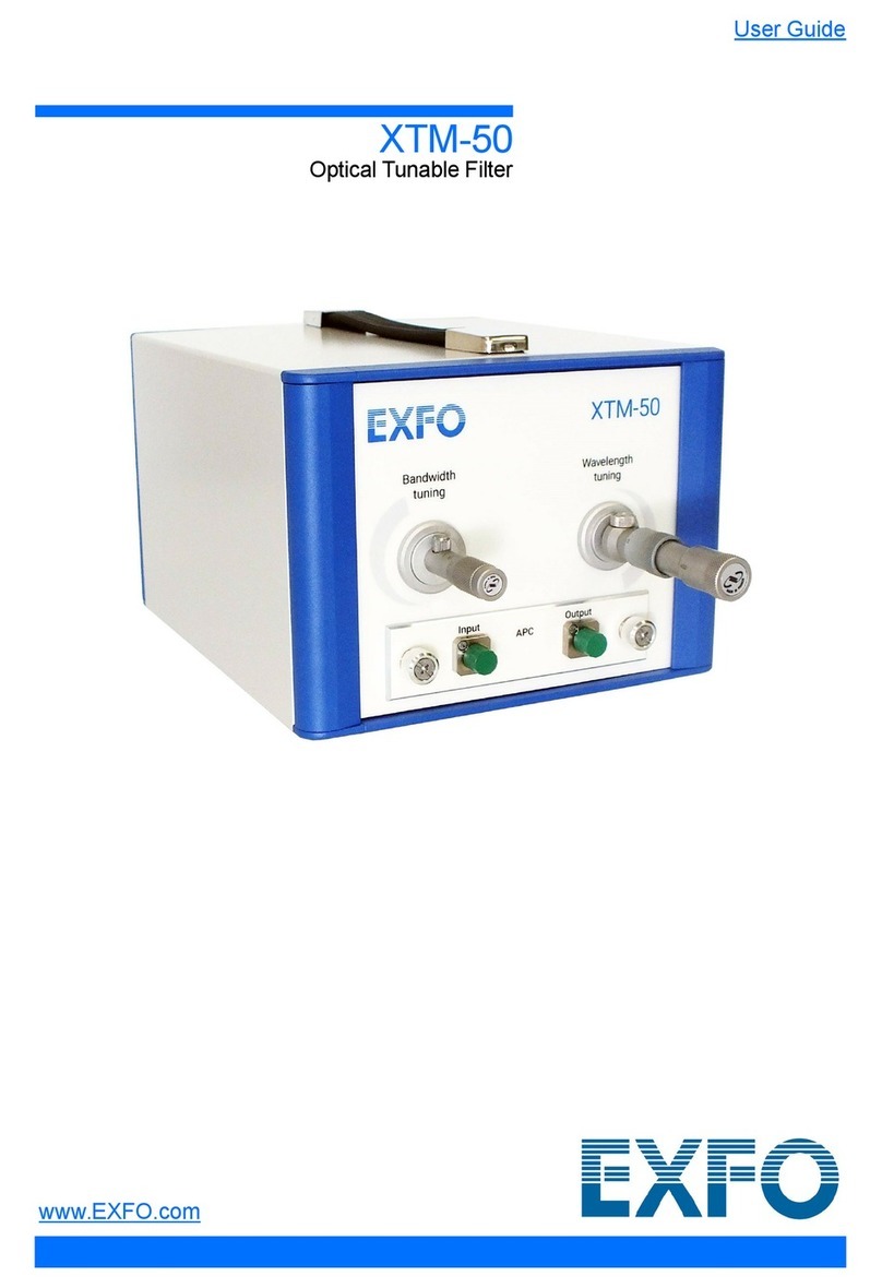
Optical Tunable Filter
www.EXFO.com

Copyright Information
ii XTA-50
Copyright Information
Copyright © 2021–2022 EXFO Inc. All rights reserved. No part of this publication may be
reproduced, stored in a retrieval system or transmitted in any form, be it electronically,
mechanically, or by any other means such as photocopying, recording or otherwise,
without the prior written permission of EXFO Inc.(EXFO).
Information provided by EXFO is believed to be accurate and reliable. However, no
responsibility is assumed by EXFO for its use nor for any infringements of patents or other
rights of third parties that may result from its use. No license is granted by implication or
otherwise under any patent rights of EXFO.
EXFO’s Commerce And Government Entities (CAGE) code under the North Atlantic Treaty
Organization (NATO) is 0L8C3.
The information contained in this publication is subject to change without notice.
Trademarks
EXFO’s trademarks have been identified as such. However, the presence or absence of
such identification does not affect the legal status of any trademark.
Units of Measurement
Units of measurement in this publication conform to SI standards and practices.
Patents
The exhaustive list of patents is available at www.EXFO.com/patent.
Version number: 3.0.0.2
Information in this document applies to the XTA-50 embedded software package
version 3.0.x

Contents
Optical Tunable Filter iii
Contents
Copyright Information .........................................................................................................................................ii
Regulatory Information .......................................................................................................................................v
1 Introducing the XTA-50 .........................................................................................................1
Technical Specifications .......................................................................................................................................1
XTA-50 Overview .................................................................................................................................................3
Conventions .........................................................................................................................................................8
2 Safety Information ................................................................................................................9
Other Safety Symbols on Your Unit ...................................................................................................................10
Electrical Safety Information ..............................................................................................................................11
3 Getting Started with Your XTA-50 ......................................................................................15
Unpacking and Installing the XTA-50 .................................................................................................................15
Connecting the XTA-50 to a Power Source ........................................................................................................16
Connecting a Mouse and Keyboard to the XTA-50 ............................................................................................17
Connecting Optical Devices to the XTA-50 .........................................................................................................17
Turning on the XTA-50 and Accessing the Operating Modes .............................................................................18
Setting the Screen Brightness ............................................................................................................................20
Connecting an External Screen to the XTA-50 .......................................................................................................21
Turning off the XTA-50 ......................................................................................................................................22
4 Setting the Wavelength/Frequency and FWHM Values .....................................................23
Manually Entering the Wavelength/Frequency and FWHM Values .....................................................................24
Selecting a Channel by Using an ITU Grid ..........................................................................................................26
Defining and Running a Sequence of Wavelength/Frequency and FWHM Values ..............................................30
Enabling/Disabling the Backlash Suppression Mechanism .................................................................................35
5 Remotely Controlling the XTA-50 .......................................................................................37
Installing/Updating and Starting the XTA-50 Remote Program ..........................................................................37
Switching Between Remote and Local Mode .....................................................................................................38
Remotely Controlling the XTA-50 via USB-B .......................................................................................................39
Remotely Controlling the XTA-50 via Ethernet ...................................................................................................42
Command/Answer Syntax ..................................................................................................................................46
6 Maintenance ........................................................................................................................49
Updating the XTA-50 Firmware Version .............................................................................................................50
Updating the Operating System Version (Security Updates) ..............................................................................51
Accessing the Operating System ........................................................................................................................52
Cleaning Optical Connectors ..............................................................................................................................53
Cleaning the XTA-50 ..........................................................................................................................................55
Replacing Fuses .................................................................................................................................................57
Recycling and Disposal ......................................................................................................................................58
7 Troubleshooting ..................................................................................................................59
Errors .................................................................................................................................................................59
Checking the Firmware Version .........................................................................................................................60
Displaying the User Documentation ..................................................................................................................60
Contacting the Technical Support Group ...........................................................................................................61
Transportation ...................................................................................................................................................61

Contents
iv XTA-50
8 Warranty .............................................................................................................................. 63
General Information ..........................................................................................................................................63
Gray Market and Gray Market Products .............................................................................................................63
Liability ..............................................................................................................................................................64
Exclusions ..........................................................................................................................................................64
Certification .......................................................................................................................................................64
Service and Repairs ............................................................................................................................................65
EXFO Service Centers Worldwide .......................................................................................................................66
A Command Reference .......................................................................................................... 67
General System Information ..............................................................................................................................68
Wavelength/Frequency and FWHM Control .......................................................................................................69
Remote Mode Control .......................................................................................................................................76

Regulatory Information
Optical Tunable Filter v
Regulatory Information
USA Electromagnetic Interference Regulatory Statement
Electronic test and measurement equipment is exempt from FCC part 15, subpart B
compliance in the United States of America. However, EXFO Inc. makes reasonable efforts
to ensure compliance to the applicable standards.
The limits set by these standards are designed to provide reasonable protection against
harmful interference when the equipment is operated in a commercial environment. This
equipment generates, uses, and can radiate radio frequency energy and, if not installed and
used in accordance with the user documentation, may cause harmful interference to radio
communications. Operation of this equipment in a residential area is likely to cause
harmful interference in which case the user will be required to correct the interference at
his own expense.
Modifications not expressly approved by the manufacturer could void the user’s authority to
operate the equipment.
Canada Electromagnetic Interference Regulatory Statement
This equipment generates, uses, and can radiate radio frequency energy and, if not
installed and used in accordance with the instruction manual, may cause harmful
interference to radio communications. Operation of this equipment in a residential area is
likely to cause harmful interference.
Cet équipement génère, utilise et peut émettre de l'énergie radio-fréquence et, s'il n'est pas
installé et utilisé conformément à la documentation de l'utilisateur, il peut occasionner une
interférence néfaste aux communications radio. L'utilisation de cet équipement dans une
zone résidentielle est susceptible d'occasionner une interférence néfaste.
Caution: This equipment is not intended for use in residential environments and may not
provide adequate protection to radio reception in such environments.
Attention: Cet appareil n'est pas destiné à être utilisé dans des environnements résidentiels
et peut ne pas assurer la protection adéquate à la réception radioélectrique dans ce type
d'environnements.
This is a class A, group 1 product.
³Class A equipment: Equipment that is, by virtue of its characteristics, highly unlikely to
be used in a residential environment, including a home business shall be classified as
class A and shall comply with the class A limits specified in the applicable ICES
standard. Characteristics considered in this assessment include price, marketing and
advertising methodology, the degree to which the functional design inhibits
applications suitable to residential environments, or any combination of features that
would effectively preclude the use of such equipment in a residential environment.
Classe A: Matériel qui, en raison de ses caractéristiques, ne sera fort probablement pas
utilisé dans un milieu domiciliaire ni par des entreprises établies à domicile. Parmi les
caractéristiques considérées dans cette évaluation, il y a le prix, les méthodes de
commercialisation et de publicité, la mesure dans laquelle les fonctions de l'appareil
font qu'il ne se prête pas à des applications convenant au milieu domiciliaire ou toute

Regulatory Information
vi XTA-50
combinaison de ces caractéristiques qui aurait pour conséquence d'en prévenir
effectivement l'utilisation à domicile. Utilisé également pour indiquer les limites
d'émission correspondantes qui s'appliquent à un tel matériel.
³Group 1 equipment: group 1 contains all equipment which is not classified as group 2
equipment, and includes equipment such as laboratory and scientific equipment,
industrial process, measurement and control equipment.
Group 2 equipment: group 2 contains all ISM RF equipment in which radio-frequency
energy in the frequency range 9 kHz to 400 GHz is intentionally generated and used or
only used locally, in the form of electromagnetic radiation, inductive and/or capacitive
coupling, for the treatment of material for inspection/analysis purposes, or for transfer
of electromagnetic energy.
Appareils du groupe 1 : le groupe 1 réunit tous les appareils compris dans le domaine
d’application de la présente Norme, qui ne sont pas classés comme étant des appareils
du groupe 2. Le groupe 1 inclut les appareils scientifiques et de laboratoire, les
processus industriels, appareils de mesure ou de contrôle.
Appareils du groupe 2 : le groupe 2 réunit tous les appareils ISM à fréquences
radioélectriques dans lesquels de l’énergie à fréquences radioélectriques dans la plage
de fréquences comprises entre 9 kHz et 400 GHz est produite et utilisée volontairement
ou uniquement utilisée localement sous forme de rayonnement électromagnétique, de
couplage inductif et/ou capacitif, pour le traitement de la matière, à des fins d’examen
ou d’analyse ou pour le transfert d’énergie électromagnétique.
Supplier's Declaration of Conformity (SDoC)
The SDoC for your product is as follows:
CAN ICES-001 (A) / NMB-001 (A)
EU and UK Electromagnetic Compatibility Regulatory
Statement
Warning: This is a class A product. In a domestic environment, this product may cause radio
interference in which case the user may be required to take adequate measures. Your
product is suitable for use in industrial electromagnetic environments.
EU and UK Declaration of Conformity
The full text of the declaration of conformity is available at the following Internet address:
www.exfo.com/en/resources/legal-documentation.
EU Economic Operator
EXFO Solutions SAS
2, rue Jacqueline Auriol,
Saint-Jacques-de-la-Lande,
35091 Rennes Cedex 9
FRANCE

Optical Tunable Filter 1
1 Introducing the XTA-50
The XTA-50 is a flat-top tunable filter for fiber-optic component and system testing. It is
designed for closely-spaced channel selection and extraction in DWDM applications.
When an optical signal is detected at the XTA-50 input port, the input wave is directed
towards the output port after passing through the XTA-50 monochromator, which is tuned at
the center wavelength via the XTA-50 software.
Each XTA-50 provides on-board touchscreen controls and user interface to drive both
system common controls and parameters. All system operations are software-controlled
from the XTA-50 user interface.
The XTA-50 system may also be remote-operated via an external screen or standard USB-B
or Ethernet interfaces.
Technical Specifications
The following table lists the technical specifications of all XTA-50 models.
Optical Specifications
All specifications are given at 21°± 3°C after 30 minutes warm-up.
IMPORTANT
The following technical specifications can change without notice. The information
presented in this section is provided as a reference only. To obtain this product’s
most recent technical specifications, visit the EXFO Web site at www.exfo.com.
Standard Ultrafine O-bandaWide
Wavelength Range 1450–1650 nm 1480–1620 nm 1260–1360 nm 1525–1610 nm
Wavelength Resolution 1 pm 1 pm 1 pm 1 pm
Wavelength Accuracyb±30 pm ±30 pm ±30 pm ±30 pm
Wavelength Tuning
Speed
1 s 1 s 1 s 1 s
Minimum Bandwidth
(FWHM)
50 pm
(6.25 GHz)
32 pm
(4 GHz)
50 pm
(8 GHz)
50 pm
(6.25 GHz)
Maximum Bandwidth
(FWHM)
950 pm
(120 GHz)
650 pm
(80 GHz)
900 pm
(160 GHz)
5000 pm
(625 GHz)
Bandwidth Resolution 1 pm 1 pm 1 pm 1 pm
Bandwidth Tuning
Speed
1 s 1 s 1 s 1 s
Filter Edge Roll-off 500 dB/nm
typicalc800 dB/nm
typical
500 dB/nm
typicalc500 dB/nm
typicald
Insertion Loss 5 dB
(
4.5 dB typical
)e,f 5 dB
(4.0 dB typical)f,g 5 dB
(4.5 dB typical)f,h 5 dB
(4.5 dB typical)i,j
Flatness 0.2 dBk0.2 dBl0.3 dBk,m 0.2 dBn
Polarization Dependent
Loss
±0.2 dBe±0.2 dBg±0.2 dBh±0.2 dBi
Out-band Suppression
(crosstalk)
40 dB
(60 dB typical)o40 dB
(50 dB typical)o40 dB
(60 dB typical)o40 dB
(45 dB typical)o
Maximum Input Power 30 dBm 27 dBm

Introducing the XTA-50
2XTA-50
Technical Specifications
Interface and Electrical Specifications
a Specifications apply for wavelengths not equal to any water absorption line.
b With "Backlash Suppression" setting enabled.
c Between -3 and -40 dB for FWHM <800 pm.
d Between -3 and -40 dB. Typically 550 dB/nm @ FWHM=50 pm, 450 dB/nm @ FWHM=1 nm, 225 dB/nm @
FWHM=5 nm.
e From 1500 to 1600 nm & FWHM >100 pm.
f At lowest FWHM the insertion loss is 7 dB typical.
g From 1500 to 1600 nm & FWHM >60 pm.
h From 1280 to 1340 nm & FWHM >100 pm.
iForFWHM>100pm.
j At lowest FWHM the insertion loss is < 7.0 dB.
k Centered width of FWHM - 150 pm. For 150 pm < FWHM < 650 pm.
l Centered width of FWHM - 100 pm. For 100 pm < FWHM < 500 pm.
m From 1280 to 1340 nm.
n Centered width of FWHM - 150 pm. For 150 pm < FWHM < 2000 pm.
o Measured 1 nm away from the -3 dB points.
Standard Ultrafine O-band Wide
Optical interfaces
Optical Connector FC/PC or FC/APC
Optical Fiber Type SMF or PMF SMF
Remote interfaces
Ethernet RJ45 (x2) 1 Gb/s max. A shielded Ethernet cable is required.
USB-B 115 kb/s max.
Display and interfaces for external devices
Display 7 inch resistive touch-screen (res. 800x480) color TFT-LCD
External Display HDMI and DisplayPort
Mouse, keyboard USB-A 3.2 (x3), USB-A 2.0 (x1)
Electrical specifications
Input Power see Electrical Safety Information on page 11
Fuse Type (x2) 2 A Slow-acting,High-breaking, 250 V, Ø5x20 mm
(T2AH250V)
Internal clock battery 3V CR2032 (replacement by service personnel only)
Size
Dimensions (W x D x H) 254 x 385 x 154 mm (10 in x 15 1/8 in x 6 in)
Weight 6.5 kg (14.33 lb)

Introducing the XTA-50
Optical Tunable Filter 3
XTA-50 Overview
XTA-50 Overview
The XTA-50 is delivered with the following accessories:
³A power supply cord
³The calibration certificate and the test report
³A USB key containing the available drivers and user documentation
Cables for fiber-optic input/output are not provided.
Front Panel
Touch Screen
The touch screen enables you to perform all possible operations on the XTA-50.
To select a parameter, command or function on the screen, touch the corresponding
command with the tip of your finger or a touch screen stylus device.
If you apply simultaneous pressure with two or more fingers, the touchscreen will not
function properly.
Optical Connectors
The two following optical connectors, protected by a dust cap, are located on the front
panel:
³IN: channel filter input port.
³OUT: channel filter output port.
The two optical connectors are mounted on a drawer, which enables you to access the
internal optical connectors for cleaning (see Cleaning Optical Connectors on page 53).
Connector’s
drawer
Touch screen
On switch
Retractable Leg
Optical
connectors

Introducing the XTA-50
4XTA-50
XTA-50 Overview
On Switch
The label identifies the on button that enables you to turn on the XTA-50 (see Turning
on the XTA-50 and Accessing the Operating Modes on page 18).
Retractable Legs
The retractable legs enable you to tilt the XTA-50 upward for convenient purpose, so that it
stands on both front legs and the rear feet (see Unpacking and Installing the XTA-50 on
page 15).

Introducing the XTA-50
Optical Tunable Filter 5
XTA-50 Overview
Rear Panel
Cooling Fan
The cooling fan extracts warm air from inside. Ventilation holes for air input are located on
the top and bottom sides of the XTA-50.
Power Input
The XTA-50 is equipped with a self regulating power supply.
The fuse holder contains two fuses to protect the XTA-50 from overcurrent (see Technical
Specifications on page 1 for fuse type).
USB Ports
³USB-A ports enable you to connect a USB keyboard and a USB mouse. Do not connect
a computer to this port.
The label identifies the USB-A 3.0 ports, the identifies the USB-A 2.0
ports.
³USB-B port enables you to connect a computer for remote control via USB.
For more details, see Remotely Controlling the XTA-50 via USB-B on page 39.
Ethernet Ports
The label identifies the Ethernet RJ45 port, which enables you to connect a
computer/network for Ethernet remote control.
³Ethernet port #1:
This port is associated with a DHCP server. It can be used to connect directly a
computer that will be assigned automatically an IP address.
³Ethernet port #2:
USB-A
ports (x4)
Ethernet port #1
(DHCP)
Audio port
(unused)
Cooling fan USB-B port
HDMI port
Fuse holder
Ethernet port #2
Power switch
Power cord
connector
DisplayPort

Introducing the XTA-50
6XTA-50
XTA-50 Overview
You can configure this port manually or automatically through a remote DHCP server.
For more information, see Remotely Controlling the XTA-50 via USB-B on page 39.
External Screen Connectors
You can connect two external screens to the following ports:
³DisplayPort port (x2)
³HDMI port (x2)
For more details, see Connecting External Screens to the XTA-50 on page 21.

Introducing the XTA-50
Optical Tunable Filter 7
XTA-50 Overview
Labels and markings
Label Description
Identification of the product.
Indicates serial number, model, options (if any) and date
of manufacture.
Manufacturer identification.
Indicates contact information of the manufacturer.
Indicates an injury hazard. It appears on a location that
requires special instructions for proper use: see Safety
Information on page 9.
Fuse type.
See Technical Specifications on page 1.
EFUP label (RoHS China).
See Chinese Regulation on Restriction of Hazardous
Substances (RoHS) on page 81.
WEEE symbol for recycling.
See Recycling and Disposal on page 58.
Safety certification label.
Canadian certification.
See Regulatory Information on page v.
UK conformity assessment.
See Regulatory Information on page v.
CE marking.
See Regulatory Information on page v.
Windows license label
The XTA-50 embeds Windows 10.
Warranty seal.
The XTA-50 cover must not be open, otherwise the
warranty is not valid anymore.
MANUFACTURED
OPTIONS
MODEL
SERIAL NUMBER
Made in France
xxxxxxxx xxxx
XTA-50
xxxxxxxxxxxx
xxxxxxxxxxxx

Introducing the XTA-50
8XTA-50
Conventions
Conventions
Before using the product described in this guide, you should understand the following
conventions:
WARNING
Indicates a potentially hazardous situation which, if not avoided, could result in
death or serious injury. Do not proceed unless you understand and meet the
required conditions.
CAUTION
Indicates a potentially hazardous situation which, if not avoided, may result in
minor or moderate injury. Do not proceed unless you understand and meet the
required conditions.
CAUTION
Indicates a potentially hazardous situation which, if not avoided, may result in
component damage. Do not proceed unless you understand and meet the required
conditions.
IMPORTANT
Refers to information about this product you should not overlook.

Optical Tunable Filter 9
2 Safety Information
WARNING
Do not install or terminate fibers while a light source is active. Never look directly
into a live fiber and ensure that your eyes are protected at all times.
WARNING
The use of controls, adjustments and procedures, namely for operation and
maintenance, other than those specified herein may result in hazardous radiation
exposure or impair the protection provided by this unit.
WARNING
If the equipment is used in a manner not specified by the manufacturer, the
protection provided by the equipment may be impaired.
WARNING
Use only accessories designed for your unit and approved by EXFO. For a complete
list of accessories available for your unit, refer to its technical specifications or
contact EXFO.
IMPORTANT
Refer to the documentation provided by the manufacturers of any accessories used
with your EXFO product. It may contain environmental and/or operating conditions
limiting their use.
IMPORTANT
When you see the following symbol on your unit , make sure that you refer
to the instructions provided in your user documentation. Ensure that you
understand and meet the required conditions before using your product.
IMPORTANT
When you see the following symbol on your unit , it indicates that the unit is
equipped with a laser source, or that it can be used with instruments equipped
with a laser source. These instruments include, but are not limited to, modules and
external optical units.

Safety Information
10 XTA-50
Other Safety Symbols on Your Unit
One or more of the following symbols may also appear on your unit.
IMPORTANT
Other safety instructions relevant for your product are located throughout this
documentation, depending on the action to perform. Make sure to read them
carefully when they apply to your situation.
Symbol Meaning
Direct current
Alternating current
The unit is equipped with an earth (ground) terminal.
The unit is equipped with a protective conductor terminal.
The unit is equipped with a frame or chassis terminal.
On (Power)
Off (Power)
OR On/off (Power)
Fuse

Safety Information
Optical Tunable Filter 11
Electrical Safety Information
This unit uses an international safety standard three-wire power cable. This cable serves as
a ground when connected to an appropriate AC power outlet.
The color coding used in the electric cable depends on the cable. New plugs should meet
the local safety requirements and include:
³adequate load-carrying capacity
³ground connection
³cable clamp
WARNING
³If you need to ensure that the unit is completely turned off, disconnect the
power cable.
³Use only the certified power cord that is suitably rated for the country where
the unit is used.
³Replacing detachable MAINS supply cords by inadequately RATED cords may
result in overheating of the cord and create a risk of fire.

Safety Information
12 XTA-50
Electrical Safety Information
WARNING
³Use this unit indoors only.
³Do not remove unit covers during operation.
³Operation of any electrical instrument around flammable gases or fumes
constitutes a major safety hazard.
³To avoid electrical shock, do not operate the unit if any part of the outer
surface (covers, panels, etc.) is damaged.
³Only authorized personnel should carry out adjustments, maintenance or
repair of opened units under voltage. A person qualified in first aid must
also be present. Do not replace any components while the power cable is
connected.
³Your unit is equipped with an internal replaceable clock battery to keep time
and date accurate. Only authorized personnel can replace this battery.
Attempting to replace it yourself could seriously compromise your safety.
³Use only fuses with the required rated current and specified type
(T2AH250V). Do not use repaired fuses or short-circuited fuse holders. For
more information, see the section about replacing the fuses in this user
documentation.
³Unless otherwise specified, all interfaces are intended for connection to
Safety Extra Low Voltage (SELV) circuits only.
³Capacitors inside the unit may be charged even if the unit has been
disconnected from its electrical supply.
CAUTION
Position the unit so that the air can circulate freely around it.

Safety Information
Optical Tunable Filter 13
Electrical Safety Information
Equipment Ratings
Temperature Operation +15 °C to +35 °C (+59 °F to +95 °F)
Storage -20 °C to +60 °C(-4 °F to 140 °F)
Performance guaranteed temperature 21°± 3°C after 30 minutes warm-up
Relative humidity 80 % for temperatures up to 31°C decreasing
linearly to 50 % relative humidity at 40°C
Maximum operation altitude < 2000 m (6562 ft)
Pollution degree 2
Overvoltage category II
Measurement category Not rated for measurement categories II, III, or IV
Input powera
a. Not exceeding ± 10 % of the nominal voltage.
100–240 V ; 50/60 Hz; 1.2–0.5 A
CAUTION
³The use of voltages higher than those indicated on the label affixed to your
unit may damage the unit.

Table of contents
Other EXFO Water Filtration System manuals
Popular Water Filtration System manuals by other brands

Philips
Philips AUT7006 user manual

Frizzlife
Frizzlife G Series owner's manual

Thermo Scientific
Thermo Scientific 1403 Series operating manual

SunSun
SunSun CUV-1 Series Operation manual

PREMIER TECH
PREMIER TECH REWATEC OM0006 Owner's manual and installation guide

Watts
Watts OneFlow OFTWH Installation, operation and maintenance manual