HIOS CL-9000 User manual

高トルク電動ドライバー
CL-9000
プッシュスタート方式
(ショックレススタンド付き)
取 扱 説 明 書
(2019 年 5 月現在 )
日本語 P1-P3
中文 P4-P6
English P7-P9
株式会社
〒131-0045 東京都墨田区押上 1-35-1
TEL:03-6661-8777
FAX:03-6657-0888
取扱説明書 No.WT-A014
19A

- 1 -
■ 安全に使用するための注意
1. ビットを着脱する時は、ドライバーが通電していないことを確認して行って下さい。
プッシュ式スタートはちょっとした加圧でもすぐにドライバーは回転します。不用意な加圧によりビット部の高速回
転で思わぬ事故を招く場合がありますので、ビット部に触れる前に、ドライバー本体の⑨FOR/OFF/REV スイッチを必
ず OFF(中立)の位置に設定するか、又は電源スイッチを「切」にして、ドライバーが通電していない状態で行って
下さい。
2. 高トルクはかなりの衝撃があります。⑩スタンド台は安定した作業テーブル等にしっかりボルトで固定してドライバー
を稼働させて下さい。
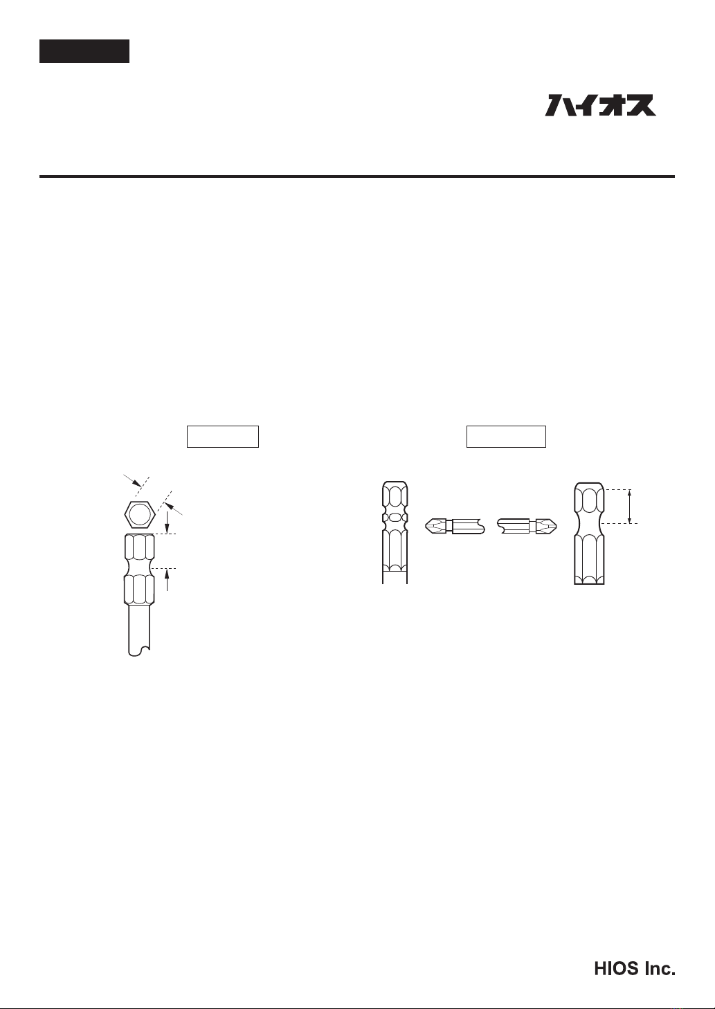
3. 安全使用のため、下記規準に準じたビットをご使用下さい。
(ご注意)市販ビットの不適合とするタイプは、CL-9000 には絶対に使用しないで下さい。
4. ドライバー及び電源はその機能と安全を維持するため、水や油等が入りやすい所での使用は絶対に避けて下さい。
5. 落下やその他の衝撃は故障及び機能低下の原因になります。ドライバー及び電源の取扱いには十分にご注意下さい。
6. 回転方向を切り替える時は、⑨ FOR/OFF/REV スイッチを一旦 OFF(中立)に入れ、必ずモーターの回転を完全に停止
させて切換えて下さい。
7. CL-9000 は外部カーボン式ですが、お客様側での交換はできません。
カーボンブラシの摩耗粉による絶縁低下を防ぐ為、交換の目安として下記を参照して弊社サービス部までお出し下さ
い。
①使用目安 100 万回、又は1年間の使用時点においてドライバーの保守点検を行って下さい。
②使用中、回転ムラ、異音、過熱、パワー不足等の症状がありましら、使用を中止して修理にお出し下さい。
8. アースは必ずお取り下さい。
日 本 語 高トルク電動ドライバー
CL-9000
プッシュスタート方式
(ショックレススタンド付き)
株式会社
東京都墨田区押上 1-35-1
TEL:03-6661-8777
FAX:03-6657-0888
適合ビット 不適合ビット
6.35
9.0
9.0
適合ビットは六角ビットの
対辺 6.35mm、ビ ッ ト エ ン
ドから溝までの長さが 9mm
規格です。
ビットエンドからの
長さが 9mm の規格
でないタイプ
Wビット
2本溝ビット

- 2 -
■ 取扱い手順
1. ⑩スタンド台を作業台等に固定して下さい。
スタンド台は衝撃を受けますので、3ヶ所の取付孔でしっかりと固定して下さい。
2. ⑥ショックレスホルダーを①支柱に通して、⑫スライドアームの高さを設定して下さい。
⑦蝶ねじをゆるめ、⑧ショックレス受止めを上下に動かし、作業のしやすい高さの位置で固定して下さい。⑦蝶ねじ
で固定して下さい。
(ご注意)
固定するねじは衝撃でゆるむ事がありますので、定期的に点検を行って下さい。
3. ビットの先端形状が締付けねじの溝に対して適合しているか、確認して下さい。
※作業中のねじ頭の損傷を避けるために確認して下さい。
4. ビットをドライバーに装着して下さい。
⑮ジョイントシャフトカラーをボデイ側に押し込み、ビットを装着します。
※ビットが確実に装着していることを確認して下さい。
5. ③ドライバーコード(5芯)をドライバーと②電源に接続して、電源コードを AC100V コンセントに接続して下さい。
電源側の入/切スイッチを「入」に入れて、スイッチランプが点灯することを確認して下さい。
6. 作業に必要な出力トルクを設定して下さい。
トルク調整ナットを目盛の位置に設定するだけで、表示してあるトルク値が得られ
ます。
⑯トルク調整ナットストッパーを緩め⑭トルク調整ナットを回転させておおよその
目盛の位置(イラスト)にセットします。
※ トルク調整の位置が決まったら、⑯調整ナットストッパーをしっかり締め付けて
固定させて下さい。
(ご注意)
「出力トルクの数値」はおおよそのトルク値を得る目安として、ご利用下さい。
7. 次に1本のねじをテストとして締付けて下さい。
ドライバーの⑨FOR/OFF/REV スイッチを FOR(正転)に入れ、ビット先端部をね
じ頭に軽く押しつけて、ドライバーを起動させて下さい。ねじが締まったところで、
ねじ頭からビット先端を離します。
8. 締付けたねじをハイオストルクメーターを使ってねじの緩み、増締めを測定します。ねじの締付けが弱ければトルク
調整ナットを締め上げ、強ければ少しゆるめます。
このような微調整で、作業に適したトルク調整目盛の位置を見つけて下さい。
9. 固く締まったねじをゆるめるときは、⑨FOR/OFF/REV スイッチを REV(逆転)に入れ、ドライバーを逆回転させて下
さい。固く締まったねじでも数回のインパクトが働き、緩んできます。
(ご注意)
FOR / REV 方向の切換をする時、ドライバーが回転している場合はモーターを一旦停止させて、行って下さい。
ねじ締めのトルクチェック及びドライバーのトルク設定にはハイオス計測器のご利用をお薦めします。
● ねじの緩みトルク、増締めトルクの計測には…HDP シリーズをご利用下さい。
● 電動ドライバーのトルク設定や、トルクドライバー、トルクレンチ等の測定具のチェックには…HP シリーズが
あります。
・ホームページでトルク計測器をご覧いただけます。 ハイオスホームページ:www.hios.com
目盛は出力トルク値を
表示しています。
N•m
- 3 -
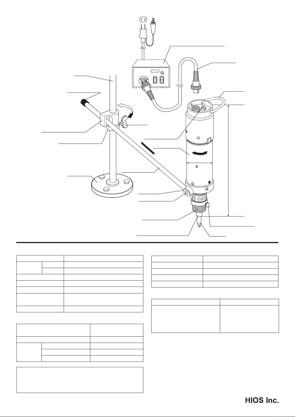
■ CL-9000 ショックレススタンド
構成図
(ご注意)
⑰タレット固定ねじは衝撃でゆるむことがあります。
定期的に点検を行って下さい。
52
250 mm
HIOS
I
o
2
1
I
ON
O
OFF
POWER SUPPLY
①支柱
④アームキャップ
⑥ ショックレ ス ホ ルダ ー
⑧ ショックレ ス 受 止 め
⑦蝶ねじ
⑫スライドアーム
⑩スタンド 台
⑨FOR/REVスイッチ
(中立付)
⑪回転グリップ
⑬ タ レ ット
⑰タレット固定ねじ
⑤ハンガー
③5芯コード
②専用電源(別売)
⑭トルク調整ナット
⑮ジョイントシャフトカラー
⑯調整ナットストッパ ー
ビ ット
■ ドライバー仕様
CL-9000
管理トルク
範囲
N•m 1.2 - 5
(kgf•cm) (12 - 50)
トルク切替 無段階調整
無負荷回転速度 (r.p.m) 530
締付可能ねじ目安(mm) 4.0 - 6.0
重さ (g) 2,360
( ドライバーコードとスライドアーム含む )
適合ビット 六角ビット 対辺 6.35mm
■ ショックレススタンド仕様
スライドアーム(mm)
()内は有効スライド範囲 530 (475)
支柱の高さ(mm) 570
スタンド台 台の高さ(mm) 8
取付ボルト孔内径(mm) 6
取付ボルト距離(mm) 52(正三角形1辺の長さ)
部品の構成 各1ヶ
●スタンド ASSY:支柱、スタンド台、ショックレス受止め、蝶ねじ
●アーム ASSY:ショックレスホルダー、アームキャップ付スライド
アーム、タレット、タレット固定ねじ
■ CLT-80(専用電源)仕様
一次側入力電源 AC 100-240V 47-63Hz
二次側出力 HI:DC30V LOW:DC20V(2 段切替式)
サイズ(mm) 114 (W)×215 (D)×52 (H)
重量(kg) 1.6
AC コード長(m) 1.8 ( アース付インレットコード )
■ 添付品
ビット ドライバーコード
六角ビット
対辺 6.35 mm
⊕ #2 ∅ 7 × 100 mm
⊕ #3 ∅ 7 × 100 mm
各1本
2 m (5P)
1本
- 4 -
使用安全上的注意
1.拆装刀头时、请确认螺丝刀是否处在绝源状态。
按压起动式只需轻轻一按就可起动。由于不注意按压会使刀头部高速旋转引起意外事故、所以在触摸刀头部前、
螺丝刀本体⑨ FOR/OFF/REV 开关必须设定在 OFF(中间)的位置、或关闭电源开关
(“切”的位置)使螺丝刀处在绝源状态。
2.大扭矩型会有相当的冲击、请用螺栓把⑩支座结实地固定在稳定的操作台等以后使用螺丝刀。
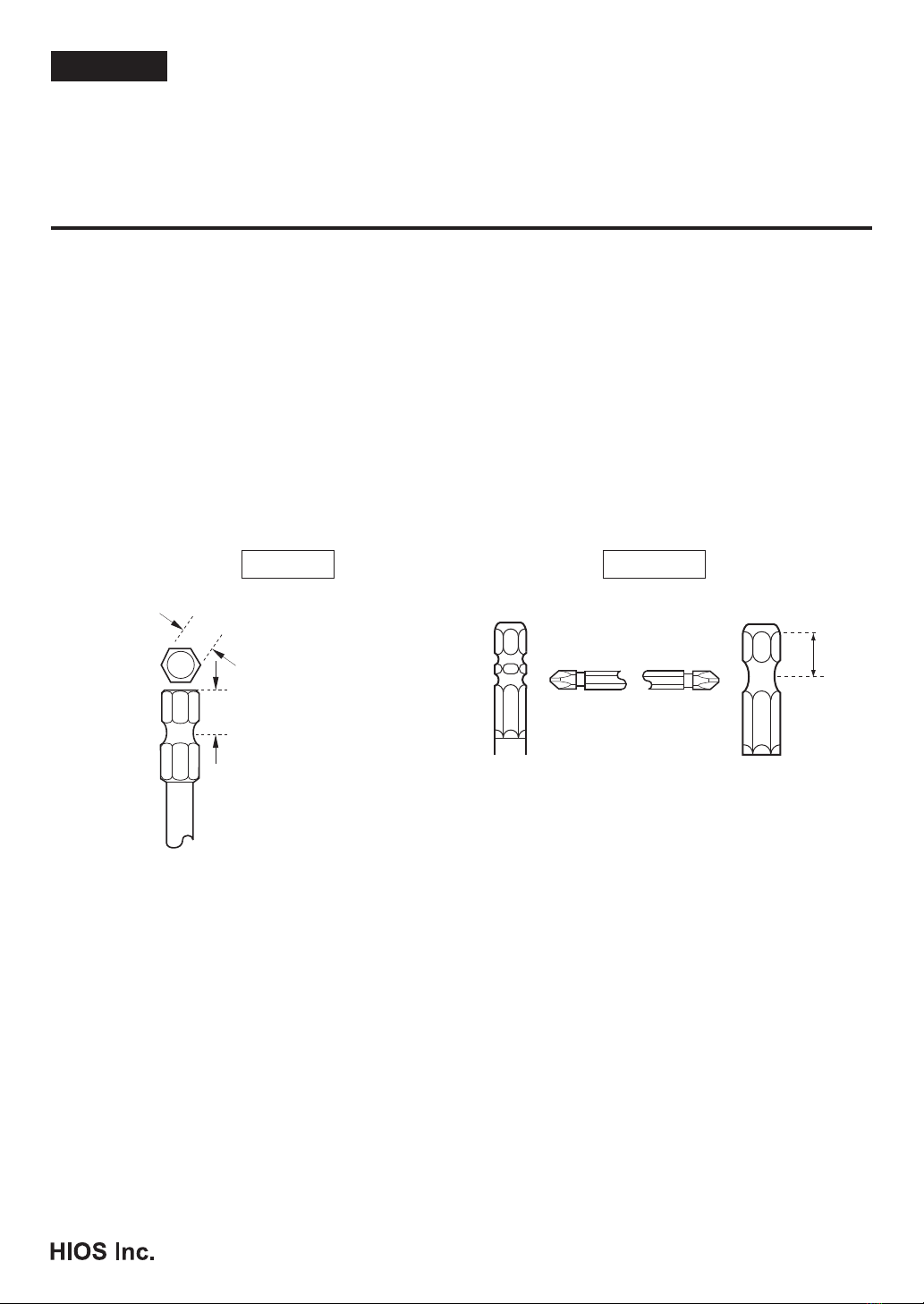
3.为了安全、请按照下面规格的刀头进行使用。
(请注意)若市售的刀头型号不符、CL-9000 不能使用。
4.为了维持螺丝刀以及电源的机能和安全、请绝对避免在易进水或油等场所使用。
5.坠落或其它的冲击是导致故障和机能低下的原因。请充分注意螺丝刀以及电源的使用。
6.切换旋转方向时、⑨ FOR/OFF/REV 开关一旦处在 OFF(中间)部位、请必须使发动机完全停止后进行切换。
7.CL-9000 是外部碳刷式、客户方不能交换。
为防止碳刷的磨耗粉引起的绝缘低下、作为交换基准请参照以下的内容、提交弊社营业部。
①使用基准为 100 万回,另外请以一年使用为时点进行螺丝刀的检侧。
②使用中如发生旋转紊乱、异音、过热、能量不足等情况,请停止使用并提交修理。
8.请务必取下接地线。
中 文 大扭矩型电动螺丝刀
CL-9000
按压起动式
( 付吸震支架 )
株式会社 HIOS
总公司邮编 131-0045
东京都墨田区押上 1-35-1
TEL:81-3-6661-8821
FAX:81-3-6661-8828
适用刀头 不适用刀头
6.35
9.0
9.0
适用刀头是六角对边距
6.35mm、刀头末端到凹部长
度 9mm 规格的刀头。
刀头末端到凹部长度
不为 9mm 规格的不能
安装。
W刀头
2个凹部刀头

- 5 -
使用顺序
1.⑩请将支座固定在操作台上。
因支座承受冲击、请用三处安装孔来稳固地进行固定。
2.请将⑥吸震托架通过①支柱、设定⑫滑动臂的高度。
拧松⑦蝶形螺丝、上下移动⑧吸震托环、在操作轻松高度处固定。用⑦蝶形螺丝固定。
(请注意)
用于固定的螺丝会因冲击而松动、请定期进行检测。
3.请确认刀头的先端形状是否与适用螺丝的凹部吻合。
※ 为避免操作中螺丝头的损坏请进行确认。
4.请将刀头安装到螺丝刀上。
⑮将接合轴按进主体侧、装上刀头。
※ 安装后、确认刀头是否确实已安装好。
5.③请将螺丝刀电源线(5芯)与螺丝刀
②电源 CLT-80 连接、电源线与 AC220V 插座进行连接。
电源侧开/关的开关处于「开」、请确认开关指示灯是否亮灯。
6.请设定操作所需的输出扭矩。
只需将扭矩调节螺母设定在所需分度的位置上
就可得到所表示的扭矩值。
(请注意)
请把「输出扭矩值」作为大概扭矩值的基准来利用
・拧松⑯扭矩调节螺母固定螺丝⑭扭矩调节螺母调节到大约基准的位置
※ 扭矩调节决定后、⑯调节螺母固定螺丝固定好。
7.然后将1个螺丝试验性地拧紧。
将螺丝刀⑨ FOR/OFF/REV 开关拨到 FOR(正转)处、刀头先端部轻轻按接到螺丝头处、起动螺丝刀。当螺丝拧紧时、
将刀头先端从螺丝头处离开。
8.拧紧的螺丝使用 HIOS 扭矩测试仪测量螺丝的松缓度、拧紧度。螺丝旋紧程度如果弱可将扭矩调节螺母拧紧、若强
可稍拧松。请这样通过微调节找到适合操作的扭矩调节基准。
9.旋开拧紧的螺丝时、将⑨ FOR/OFF/REV 开关拨到 REV(逆转)处、使螺丝刀逆旋转。拧紧的螺丝也会通过数次有
效的冲击变松。
(请注意)
切换 FOR / REV 方向时、螺丝刀在转动的情况下请先暂时停止发动机、再进行操作。
螺丝旋入的扭矩检测和螺丝刀的扭矩设定建议利用 HIOS 测量仪。
●螺丝的旋出扭矩、增旋入扭矩的计测 ...请利用 HDP 系列。
●电动螺丝刀的扭矩设定、扭矩螺丝刀、扭矩扳手等测定具的检测 ...有 HP 系列
在主页上可浏览到扭矩测量仪。
HIOS 主页:www.hios.com
分度表示扭矩的值
N•m

- 6 -
■CL-9000 吸震支架构成图
( 请注意)
⑰旋转座固定螺丝会因受冲击而松动。
请定期进行检测。
■规格
CL-9000
输出扭矩
范围
N•m 1.2-5
ibf•in 10-43
(kgf•cm) (12-50)
扭矩切换 无级调节
无负载转速(r.p.m) HI:544
LOW:360※
适用螺丝规格(mm) 4.0-6.0
重量(g) 2,360
( 重量包括螺丝刀线和滑动臂 )
适用刀头 (1/4HEX) 六角形对边距6.35mm
吸震支架
滑动臂长 (mm)
()内是有效活动范围 530(475)
支柱高度 (mm) 570
支座 座高 (mm) 8
固定螺栓孔内
(mm) 6
固定螺栓孔间
距离 (mm)
52
(正三角形边长)
※ 请只用机用小螺丝使用 20V 的输出。
■ CLT-80 规格
一次側输入 AC100V - 240V47-63Hz
二次输出 2:(30V),1:(20V)2 挡切替
外观尺寸 (mm) 114×215×52(H)mm
重量 (kg) 1.6kg
AC 电线长度 1.8m( 内接线 )
配件 备用金属配件 2 个
备用螺丝 4 个
部件构成 各1个
●支座 ASSY:支柱、支座、吸震部托架、蝶型螺丝
●滑动臂 ASSY:吸震部托架、带臂帽的滑动臂、旋转
座、旋转座固定螺丝
■附件
刀头 螺丝刀电源线
六角形对边距 6.35mm
⊕ #2∅7 ×100mm
⊕ #3∅7 ×100mm
各1个
2m(5P)
1根
52
250 mm
HIOS
I
o
2
1
I
ON
O
OFF
POWER SUPPLY
①
④
⑧
⑥
⑩
⑦
⑨
⑪
⑬
⑰
⑯
⑭
⑮
⑫
②
③
⑤
- 7 -
Precautions for Safe Operation
1. Check that the power is off before changing the bit. It takes only a slight amount of pressure for a push-to-
start driver to go into operation. Accidental pressure on the tool could result in the high-speed bit causing
unexpected damage. Before touching the bit always check to see that the power is turned off or the power
switch (FOR/OFF/REV) is set to the off position in the middle.
2. This high-torque tool delivers considerable punch. It should be operated only when the stand base is
securely bolted to a sturdy work bench.
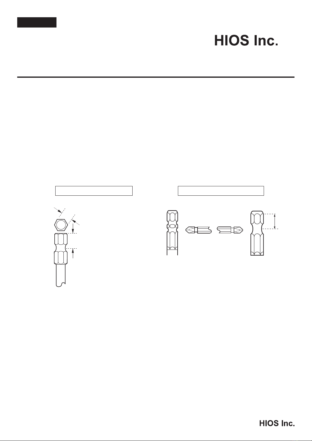
3. For safe operation use bits conforming to the standards indicated in the diagram on the left below. The
diagrams on the right indicate bits that cannot be used with the CL-9000 driver.
English
High Torque Electric Screwdriver
CL-9000
Push-to-Start Type
(comes with shockless stand)
1-35-1 Oshiage, Sumida-ku Tokyo,
Japan
TEL: 81-3-6661-8821
FAX: 81-3-6661-8828
Bits for use with CL-9000 Bits unsuitable for CL-9000
6.35
9.0
9.0
Use size 6.35 mm hexagonal
bits whose length from the
point to the bearing groove
are 9 mm.
Bits whose length from
the point to the bearing
groove is not 9 mm.
W bit
Double recess
bearing groove
4. To protect the functioning of the tool and transformer and insure their safe operation, never use them in an
environment where they might be penetrated by water, oil, etc.
5. Dropping the tool or subjecting it to strong impacts can harm it. Please exercise care it handing it and the
transformer.
6. Whenreversingdirectionofrotation,rstsetthepower switch to the off position between FOR (forward)
and REV (reverse) and wait until the driver has completely stopped turning.
7. The CL-9000 driver uses external carbon brushes that cannot be replaced by the user. In order to avoid
deterioration of insulation from brush wear, we recommend that the tool be sent to your Hios dealer for
replacement (1) after about 1 million operations, (2) when your Hios repairman recommends replacement
upon an annual maintenance check, (3) when the tool begins to show irregular rotational movement, the
motor sound is abnormal, there is overheating or the tool is no longer operating at full strength.
8. Be sure to ground the tool.
- 8 -
Operating Procedure
1. Fasten the stand base to the work bench securely, employing all three holes provided so that it will
withstand the torque delivered by the tool.
2. Pass the slide arm through the shockless holder and adjust the desired height of the arm on the stanchion
by loosening the wing screw and moving the collar. Re-tighten the wing screw.
Caution: Vibration may loosen the wing screw. Please check it periodically.
3. Checktoseethepointofthebittsthetypeofscrewtobeturned.Neglectingthischeckcanresultin
damage to screw heads.
4. Attach the bit to the driver by pushing the joint shaft collar into the body. Check that bit is firmly
attached.
5. Connect the 5-core driver cord to the CLT-80 Power Pack. Then connect
the power cord to an AC outlet. Turn the power switch of Power Pack on and
check that the power lamp lights.
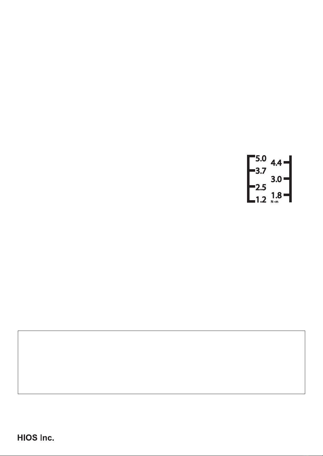
6. Use the torque adjustment nut to make the desired output torque level scale
setting.Notethatthissettingshouldbetakenasanapproximatevalue.
Make the setting by loosening the adjustment nut stopper and adjusting
the torque adjustment nut.Thegureattherightshowsthetorquescale.
When the setting has been made, re-tighten the torque adjustment nut stopper
securely.
7.Next,trytighteningonescrewasatest.Setthepower switch to the forward
(FOR) position and turn the screw by lightly applying the point of the bit to
the head of the screw. When the screw is tightened, remove the bit from the
screw head.
8. Using a Hios torque meter HDP Series*, loosen the screw, measuring the amount of torque. If the screw
wasn't tight enough, increase the driver's torque setting, or if not tight enough, decrease the torque setting.
Usethisproceduretondtherighttorquesettingforthefasteningjob.
9. To loosen a screw, set the power switch to the reverse (REV) position. The tightest screw can be loosened
by tapping the bit to the screw head a number of times.
Caution: When switching between forward and reverse drive always stop the operation of the motor by
setting the power switch to the middle position and waiting until rotation stops completely before
proceeding to the opposite drive setting.
* We recommend Hios torque meters for use in measuring tightening torque of screws and making
driver torque settings.
● UsetheHiosHDPtorquemeterseriesformeasurementoflooseningandtighteningtorqueofthe
fastened screw.
● TheHPseriesoftorquemeterscanbeusedforcheckingtorquesettingsofscrewdrivers,torque
drivers or torque wrenches.
These instruments are displayed on the Hios home page: www.hios.com
The scale indicates
output torque.
N•m

- 9 -
Parts of the CL-9000 Shockless Stand
Caution
Vibration may loosen the
turret fastening screw
over time. Please check its
tightness periodically.
■ Specications
CL-9000
Controllable
Torque Range
N•m 1.2 - 5
lbf•in 10 - 43
(kgf•cm) (12 - 50)
Torque Switching Stepless adjustment
Unloaded Rotation Speed (r.p.m)HI:544,
LOW
:360*
Screw Size (mm)4.0 - 6.0
Weight (g)
2,360
(Includes the weight of the
screwdriver cord and slide arm)
Bit Type 6.35 mm HEX bit
* DC20V output is only for Machine screw.
■ Specications of Shockless Stand
Slide arm (mm) (effective sliding range in parenthesis) 530 (475)
Height of pole(mm)570
Stand base Height of base (mm) 8
Attachment bolts inner diameter of
bolt holes(mm)6
Respective distances between
attachment bolts(mm)52
■ Specications of CLT-80 power pack
Input voltage AC100V-240V 47-63Hz
Output voltage 2:(30V), 1:(20V)Two stage settings
Size (mm) 114(W)×215(D)×52(H) mm
Weight(kg) 1.6kg
AC Cord Length 1.8m (inlet cord)
Accessories Attachment plates 2 pieces
Attachment screw 4 pieces
ASSY of Parts (one of each)
●Stand ASSY: Pole, Stand base, Collar (for shockless
holder), Wing screw.
●Arm ASSY: Slide arm, Shockless holder, Slide arm with
slide cap, Turret, Turret fastening screw.
■ Specications
Bits Power cord
6.35 mm HEX bit
⊕ #2 ∅7 x 100 mm
⊕ #3 ∅7 x 100 mm
(one of each)
2 m (5P)
1 piece
52
250 mm
HIOS
I
o
2
1
I
ON
O
OFF
POWER SUPPLY
Pole
Arm cap
Shockless holder
Collar (for shockless holder)
Stand base
Wing screw
Power switch (FOR/REV)
(off setting is the middle)
grip
Turret
Turret fastening screw
Adjustment nut stopper
Bit
Torque adjustment nut
Joint shaft collar
Slide arm
Power pack (sold separately)
5-core driver cord
Hanger

Table of contents
Other HIOS Power Screwdriver manuals

HIOS
HIOS JUKUREN BLG-BC2 series User manual

HIOS
HIOS DCD-40L User manual

HIOS
HIOS BLG Series User manual

HIOS
HIOS VZH-1820 User manual

HIOS
HIOS JUKUREN BLG-BC2 series User manual

HIOS
HIOS BLF-2000 User manual

HIOS
HIOS CL-2000 Installation manual

HIOS
HIOS CL-9000NL User manual

HIOS
HIOS VB Series User manual

HIOS
HIOS BL-2000 User manual


Popular Power Screwdriver manuals by other brands


KS Tools
KS Tools Brilliant Tools BT160100 operating instructions

Bosch
Bosch GSR/GSB 12 VE-2 PROFESSIONAL operating instructions

RODEX
RODEX RDX3365 instruction manual

ADEO Services
ADEO Services ML-CS24-36-A Assembly, Use, Maintenance Manual

Senco
Senco DS212-18V operating instructions

Parkside
Parkside PKGA 20-Li C2 Translation of the original instructions