ASGCO CHEVRON Guide

Check us out at
www.asgco.com
Customer Service
Customer Service
800-394-2358
800-344-4000
ASGCO Mfg., Inc.
301 Gordon Street
Allentown, PA 18102
610-821-0216
FAX 610-778-8991
© 2003 Copyright ASGCO Manufacturing, Inc.
24 Hour Emergency
Service and Parts
610-821-0210
®
CHEVRON
BELT CLEANERS
INSTALLATION, OPERATION
& MAINTENANCE INSTRUCTIONS
INSTALLATION, OPERATION
& MAINTENANCE INSTRUCTIONS

ASGCO Mfg., Inc. 2 CHEVRON
Important
Safety
Notice
Always observe the basic rules of safety when
working with any conveyor system. To avoid
injury and equipment damage, be sure that all
controls to the conveyor are locked out and the
power source is disconnected at all times
during installation.
Installation
Tools
Selecting a
location
for the
Chevron
In addition to the items provided by ASGCO, the following will be needed to
install the Chevron Cleaner:
1. Heavy duty file 5. Tape measure
2. Drill with 1” and ½” bits 6. Carpenter’s square
3. Cutting or burning equipment 7. Straight edge
4. Adjustable wrench 8. Allen wrench set
To ensure the most efficient cleaning operation possible, ASGCO supplies a
wide range of Chevron assemblies.
ASGCO Chevron Cleaners:
SOLID or NOTCHED
• Solid version could have 6”, 8” or 10” diameter discs
• Notched version is only supplied with 8” diameter discs
• Custom-made shafts in various lengths and with a varying number of discs
The Chevron assembly is designed to remove the fine carryback
material. When choosing a mounting location for the Chevron, it is
important to consider the space available. The Chevron assembly can
be mounted on the arc of a pulley or any section of the belt that is flat
and tight.
The belt length required is determined by the diameter of the discs
and the number of shafts. The following chart provides the distance in
inches required to install the various assemblies.
Head
Pulley
Belt Travel
Chevron Assembly mounted on arc of
pulley or flat section of belt
Snub
Pulley

ASGCO Mfg., Inc. 3 CHEVRON
Disc Four Three Shaft Two Shaft
Diameter Assembly Assembly Assembly
10” 57” 43” 29”
8” 50” 38” 26”
6” 43” 33” 23”
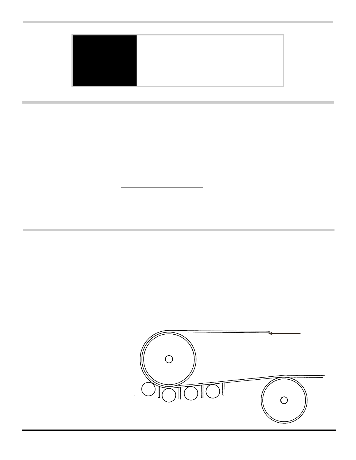
NOTE: The center point of the last shaft must be at least 10" away from any
pulley or idler that is mounted below the belt.
It is also important that the mounting location is adequate to allow the
scraped material to fall back into the main discharge chute or a dribble
chute. To ensure sufficient flow of the scraped material down the chute, an
unlined chute should have at least a 75° angle (to the horizontal); and
UHMW plastic lined chute should have at least a 65° angle (to the
horizontal).
BELT TENSION REQUIREMENTS - Because of the unique design of the
Chevron, the shafts must be mounted in a flat, tight area of the belt. The
Chevron cannot operate to its maximum effectiveness on a belt that is
loose or bowed.
ADDING IDLERS OR PULLEYS - If a sufficient mounting location cannot
be found between the head and snub pulleys, the Chevron can be located
elsewhere, provided that the proper steps have been taken to prevent the
belt from loosening or troughing in the contact area. This can be done by
mounting standard return idlers or small pulleys above the belt.
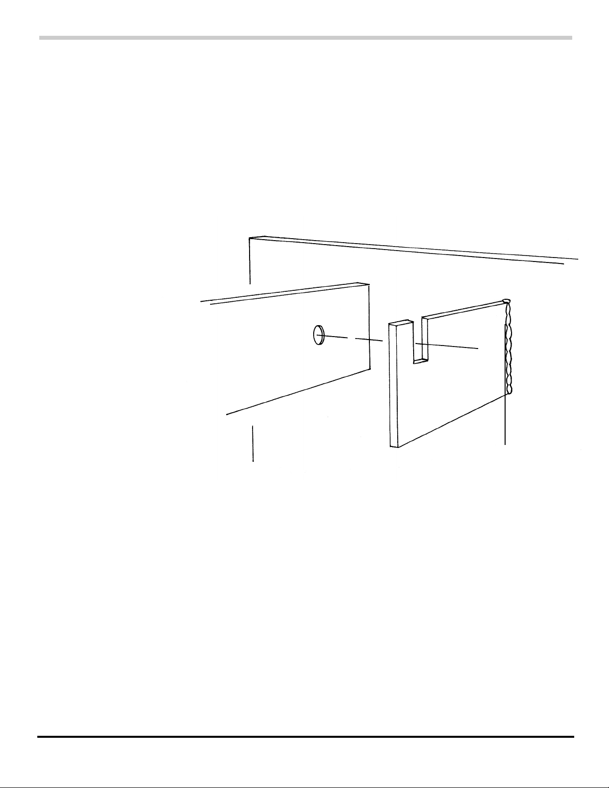
FABRICATING MOUNTING PLATES - If a chute is not present in the
desired mounting location, mounting plates can be fabricated to simulate
the sides of the chute and provide a mounting base for the Chevron shafts.
These plates are made from 1/4" to 3/8” flat stock steel and should
measure 12" to 16" high. Extend the plates the length of the Chevron
installation, with an extra 6" on each end.
Once a suitable mounting location has been chosen, the initial setup work
can begin. Proceed as follows:
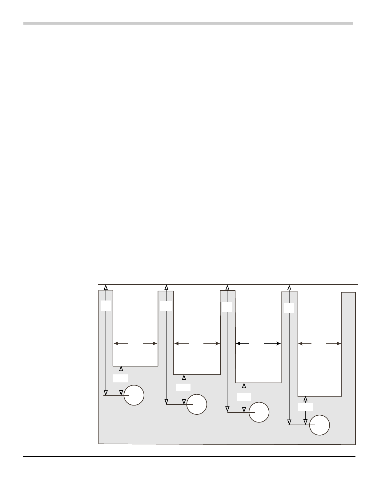
1. The first measurement will vary, depending on the disc diameter and
the size of the bearings within the pillow blocks:
A. IF USING 6" DISCS WITH I " BEARINGS, measure the distance to a
point 6" down from (perpendicular to) the belt on the chute wall.
Mark this point "X'.
B. IF USING 8" DISCS WITH 1 " BEARINGS, measure the distance to a
point 61/2" down from (perpendicular to) the belt on the chute wall.
Mark this point "X".
C. IF USING 8" DISCS WITH 13/8" OR 1 1/2" BEARINGS, measure the
distance to a point 7" down from (perpendicular to) the belt on the
chute wall. Mark this point "X'.
Initial
Setup

Head
Pulley
Belt Travel
Snub
Pulley
x
10”
ASGCO Mfg., Inc. 4 CHEVRON
D. IF USING 10" DISCS WITH 1-3/8" OR 1-1/2" BEARINGS, measure the
distance to a point 8" down from (perpendicular to) the belt on the
chute wall. Mark this point "X'.
2. Transfer point "X' to the other side of the chute wall, making sure that the
two marks are in the exact same location on both sides. These marks
represent the location points of the mounting bracket bolt of the last
Chevron shaft. Keep in mind that they must be at least 10" away from
any pulleys or idlers mounted below the returning belt.
3. Use the illustration to determine the center to center distance of the
remaining Chevron bracket mounting points. The distance between
mounting points is determined by the diameter of the Chevron discs.
10” diameter discs require a 14” center to center distance between
mounting points. 8" diameter discs require a 12" center to center
distance. 6" diameter discs require a 10" center to center distance.
While moving towards the head pulley, mark the remaining mounting
point locations on both chute walls with "X" marks as was done in Step
1, following the course of the belt for the distance that the Chevron's will
be mounted.
4. On both chute walls, scribe a line parallel to the belt and connecting
each of the "X" end points. The intersecting points are the mounting
points for the Chevron assembly and must be identical on both chute walls.
14”
10”
12”
14”
10”
12”
14”
10”
12”

IMPORTANT
For brackets mounted INSIDE
the chute wall go to Page 6
For brackets mounted OUTSIDE
the chute wall go to Page 7
ASGCO Mfg., Inc. 5 CHEVRON

ASGCO Mfg., Inc. 9 CHEVRON
To adjust the Chevron to its proper cleaning pressure, push both Chevron
mounting brackets up until the discs start to compress against the belt.
Run your hand across the top of the Chevron where it touches the belt and
bend all of the discs in the same direction. Stop adjusting upwards on the
brackets when there is a 1/1 6" to 1/8" gap between the discs across the
width of the belt.
CAUTION: Over-adjustment of the Chevron against the belt will result in
premature wear and under-adjustment will result in poor cleaning action.
Do not allow the discs to touch each other when bending them into
position.
When the Chevron has been properly adjusted, tighten the two nuts with a
slugger wrench so that vibration during operation will not cause the
adjustment to be altered.
Install a bearing cover on each bearing by stretching the 4" X 14" Neoprene
sheet over the top and under the pillow block Secure the cover by using
the bottom bolt extensions as locating pins. The bolts should protrude
through the holes in the Neoprene.
1/16” to 1/8” gap between discs when they are compressed against the belt.
14”
Neoprene sheet
Pillow Block
Note: the 1/8” gap should be measured with solid or notched disc on
surface of a Chevron.
Note: Make sure gap is measured on top of Chevron, NOT on base belt.

Chute Walls
Chevron Mounting Brackets
Head Pulley
Chute Wall
Chevron Mounting Bracket
Conveyor Belt
Pillow
Block
ASGCO Mfg., Inc. 6 CHEVRON
5. Burn or drill a 1" diameter hole at each of the "X" points on both chute
walls.
6. Insert a ¾" x 2" long bolt into each of the 1" diameter holes. Be sure to
insert the bolts from the outside of the chute wall, then place a nut and
washer on each bolt from the inside. Only hand tighten the nuts at this
time.
7. Tack weld the heads of each of the bolts on both sides of the chute wall.
When all of the bolt heads have been welded, the Chevron
installation can begin. Start with the last shaft installation and
work forward toward the head pulley.
1. Install a Chevron mounting bracket on each of the bolts. To do
this, loosen the nut, slide the bracket into position, then snug up
the nut by hand tightening. Be sure that the top of the bracket
(the part with two notches) is facing up as shown.
2. Position a Chevron shaft on top of the facing mounting brackets.(The
pillow block and bearing are shipped already mounted on the shaft.)
Fasten both pillow blocks to the bracket with 3/8" X 1½" long bolts and
hardware (flat washer, locking washer, and nut). [Don't worry about the
direction of the discs at this point.
GO TO PAGE 9
Chevron
Installation

ASGCO Mfg., Inc. 10 CHEVRON
Chute Wall
Vibro Band
Vibro Band
Mounting Bracket
Vibro Band and
Bearing Cover
Installation
Before installing the remaining Chevron shafts, the Vibro Band must be
located and installed on this shaft. Proceed as follows:
1. Position a Vibro Band mounting bracket on each side of the chute wall.
The bracket should be located with its top edge approximately 1" below
the belt and perpendicular to the ground (not the belt). The notched
end of the bracket should face up toward the belt and the center of the
chute.
IMPORTANT: There should be a 2" distance between the Vibro Band
mounting bracket and Chevron discs.
2. Weld the Vibro Band mounting brackets into position.
3. Take one of the Vibro Bands and hold it up to but not touching the belt
while resting it against the front of the brackets. From the back, mark
the two slot locations on the plastic. Drill a ½” diameter hole at the
bottom of the slot location on each side.
4. Install the Vibro Band on the side of the mounting bracket facing the
head pulley with two 3/8" X I” long bolts and hardware. Adjust it so that
it just kisses the belt across the full width.
CAUTION: The Vibro Bands do not provide cleaning action; their function
is to direct the scraped material away from the next Chevron
and direct it down into the chute. Adjusting the Vibro Bands too
tightly will cause premature wear.

ASGCO Mfg., Inc. 7 CHEVRON
5. The next measurement also varies, depending on the outside diameter
of the Chevron shaft:
A. IF THE OUTSIDE DIAMETER OF THE SHAFT IS 1 ", use a
soapstone and straightedge to scribe a vertical line 1½" up from
each of the "X" end points. Mark each of these end points "N'.
B. IF THE OUTSIDE, DIAMETER OF THE SHAFT IS 1½”, use a
soapstone and straightedge to scribe a vertical line 1¾” up from
each of the "X" end points. Mark each of these end points "A".
6. Scribe a horizontal line 21/2" long, with its center intersecting point "A”
, on both chute walls. Mark the end points of these lines "Al" and "A2".
7. Scribe vertical lines from points "Al" and "A2" to the top of each chute
wall.
8. Repeat this marking procedure on the remaining "X" points on both
chute walls.
9. Burn or drill a 1diameter hole at each of the "X” points on both chute
walls.
10. Burn or cut along the horizontal and vertical lines scribed in Steps 6-8.
Remove the chute wall material; the result will be rectangular cutouts
above each 1 diameter hole.
11. Insert a ¾" x 2" long bolt into each of the 1” diameter holes. Be sure to
insert the bolts from the inside of the chute walls. Place a flat washer,
lock washer, and nut on each bolt. Only hand tighten the nuts at this
time.
12. Tack weld the heads of each of the bolts on the inside of the chute walls.
2½” 2½” 2½” 2½”
6” 8”
7”
6½”
A1 A A2
A1 A A2
A1 A A2
A1 A A2
“X”
“X”
“X”
“X”
1½”
1½”
1¾”
1¾”
6” Disc 1” Bearing 8” Disc 1” Bearing 8” Disc 1-3/8” or
1½” Bearing
10” Disc 1-3/8” or
1½” Bearing
BELT

ASGCO Mfg., Inc. 8 CHEVRON
When all of the bolt heads have been welded, the Chevron installation can
begin. Start with the last shaft installation and work forward toward the
head pulley.
1. Install an Chevron mounting bracket on each of the bolts. To do this,
loosen the nut, slide the bracket into position, then snug up the nut by
hand tightening. Be sure that the top of the bracket (the part with two
notches) is facing up as shown.
2. Flats must be filed at the set screw locations on the end of the Chevron
shaft. To do this, position the shaft inside the pillow block and remove the
two set screws using an Allen wrench. Insert a punch into the set screw
holes and mark their positions on the shaft. Replace the set screws and
remove the shaft from the pillow block, and file the flats as indicated by
the marks.
Chevron Mounting Brackets
Head Pulley
Chevron
Installation
3. Position one end of the shaft, then the other, through the rectangular
cutouts in the chute wall.
4. Slide the pillow blocks over the shaft with the flats facing the set screws.
Tighten the set screws with an Allen wrench.
5. Fasten both pillow blocks to the bracket with3/8 " x 1 1/2" long bolts and
hardware (flatwasher, locking washer and nut).
Chute Wall
Chevron
Mounting
Bracket
Chevron Shaft
Conveyor Belt
Pillow
Block
Chute Walls

ASGCO Mfg., Inc. 12 CHEVRON
Information
Components
Diagram
2
1
3
Shaft assembly -
includes shaft, spacers,
discs and collars
Bearing - specify 1” diameter
specify 1.5” diameter
Mounting Bracket
- for 1” bearing
- for 1.5” bearing
8” notched 1” shaft
8” notched 1.5” shaft
6” plain 1” shaft
8” plain 1” shaft
8” plain 1.5” shaft
10” plain 1.5” shaft
3
2
1
4
4
1 Shaft Assembly w/o Bearings Call Customer Service w/original part number of cleaner
2 Bearing - 1” Diameter ASG-FOD-BR1
Bearing - 1½” Diameter ASG-FOD-BR2
3 Mounting Bracket for 1” Bearing ASG-FOD-MB1
Mounting Bracket for 1.5” Bearing ASG-FOD-MB2
4 Disc 8” Diameter - Notched 1” Shaft ASG-FOD-8.0D-N
Disc 8” Diameter - Notched 1.5” Shaft ASG-FOD-8.5D-N
Disc 6” Diameter - Plain 1” Shaft ASG-FOD-6.0D
Disc 8” Diameter - Plain 1” Shaft ASG-FOD-8.0D
Disc 8” Diameter - Plain 1.5” Shaft ASG-FOD-8.5D
Disc 10” Diameter - Plain 1.5” Shaft ASG-FOD-10.5D
Key Description Part Number
Call your ASGCO Distributor for any questions or replacement parts

ASGCO Mfg., Inc. 11 CHEVRON
The second shaft is installed with all of the discs bending in the opposite
direction. Continue to alternate the direction of the discs in each
subsequent shaft installation.
Maintenance
Head
Pulley
Snub
Pulley
Move on to the next Chevron shaft installation, using this same step-by-
step procedure. Remember that the direction of the discs must be
alternated on each subsequent installation.
• When used in a 24-hour operation, the Chevron must be adjusted every
four months. Grease hoses should be installed if the Chevron mounting
location prevents easy lubrication.
• Grease the bearing periodically.
• Operation of the conveyor belt without material should be kept to a
minimum.
Table of contents
Popular Ultrasonic Jewelry Cleaner manuals by other brands

General Pipe Cleaners
General Pipe Cleaners Mini-Rooter XP operating instructions

Hobot
Hobot 198 user manual

Makita
Makita DCL184 instruction manual

Vibrograf
Vibrograf Portescap Mark V operating instructions

Makita
Makita CL104DWYX instruction manual

Ribimex
Ribimex PRCEN001/1530 Instruction manual and maintenance