© Ashcroft Inc. 2022, 250 East Main Street, Stratford, CT 06614-5145, USA, Tel: 203-378-8281, Fax: 203-385-0357, www.ashcroft.com
All sales subject to standard terms and conditions of sale. ZT12_Transducer_I&M011-10307_RevA_11-16-22 6
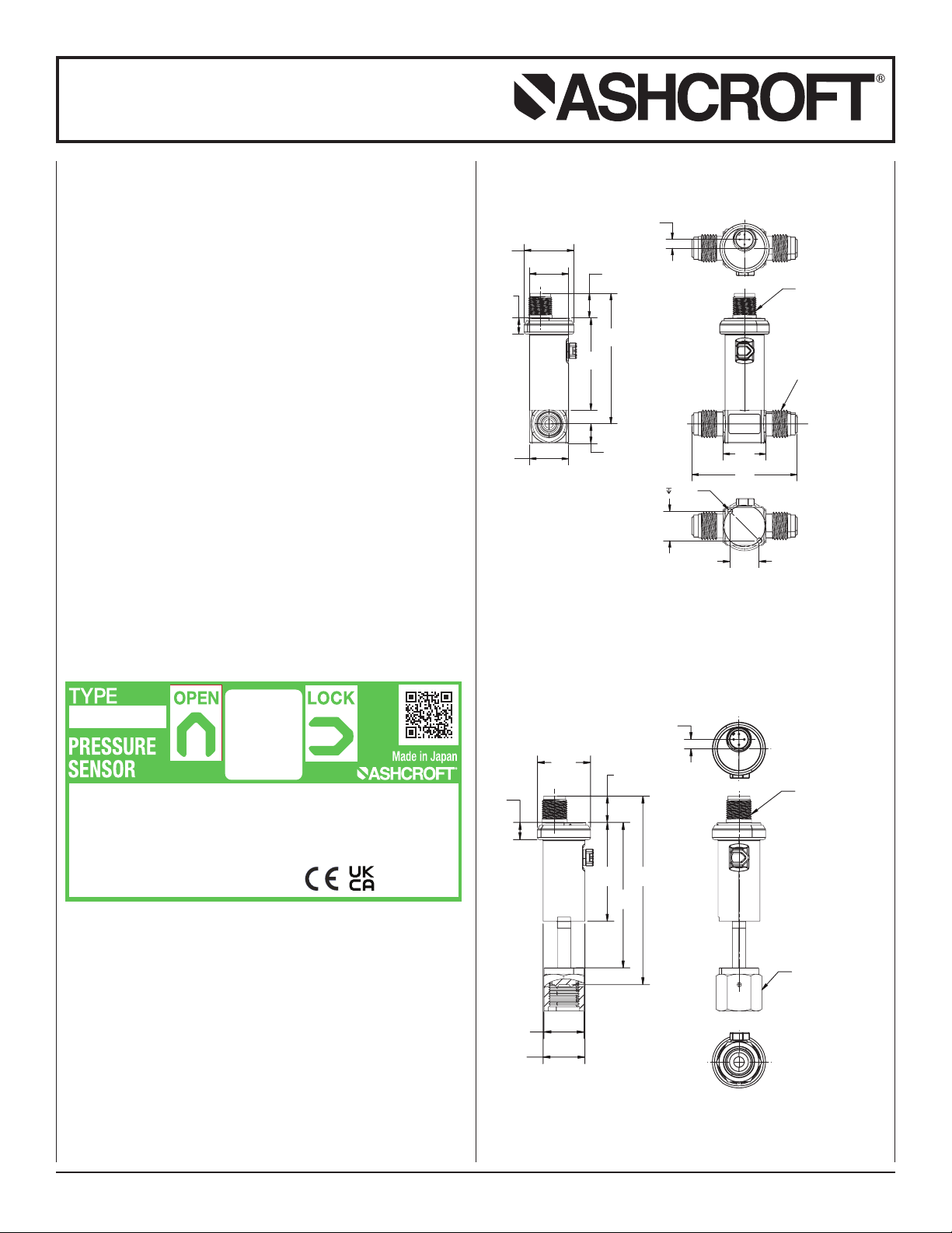
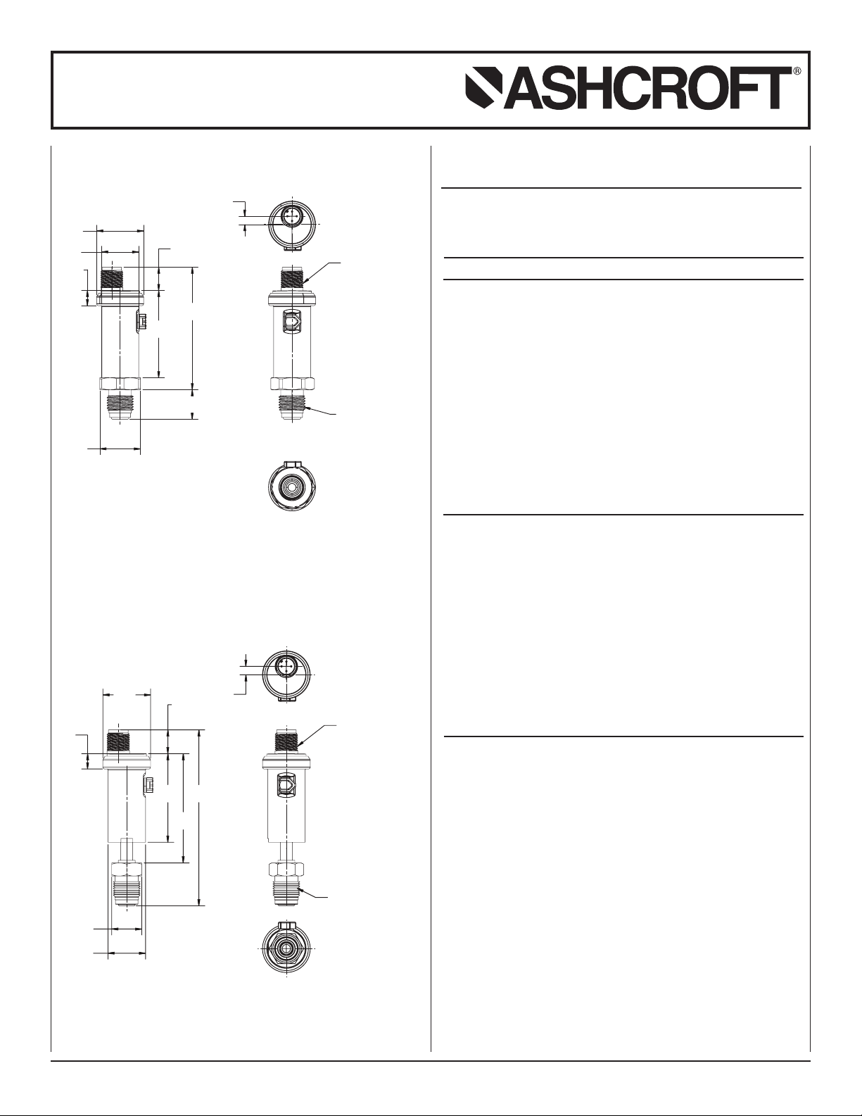
Installation and Maintenance Instructions
for ZT12 High Purity Transmitter
• Zero and span adjustment are performed
by rotating zero/span potentiometer with
resin or ceramic Phillips screwdriver. Be
careful not to mistake the position and
orientation of each adjustment.
• Avoid placing an excessive load [within 5N,
10 sec.] on the zero/span adjustment poten-
tiometer as this can lead to damage.
• Be extremely careful not to cause a short
circuit with the screwdriver.
• Use properly calibrated and traceable
instrumentation to verify adjustments.
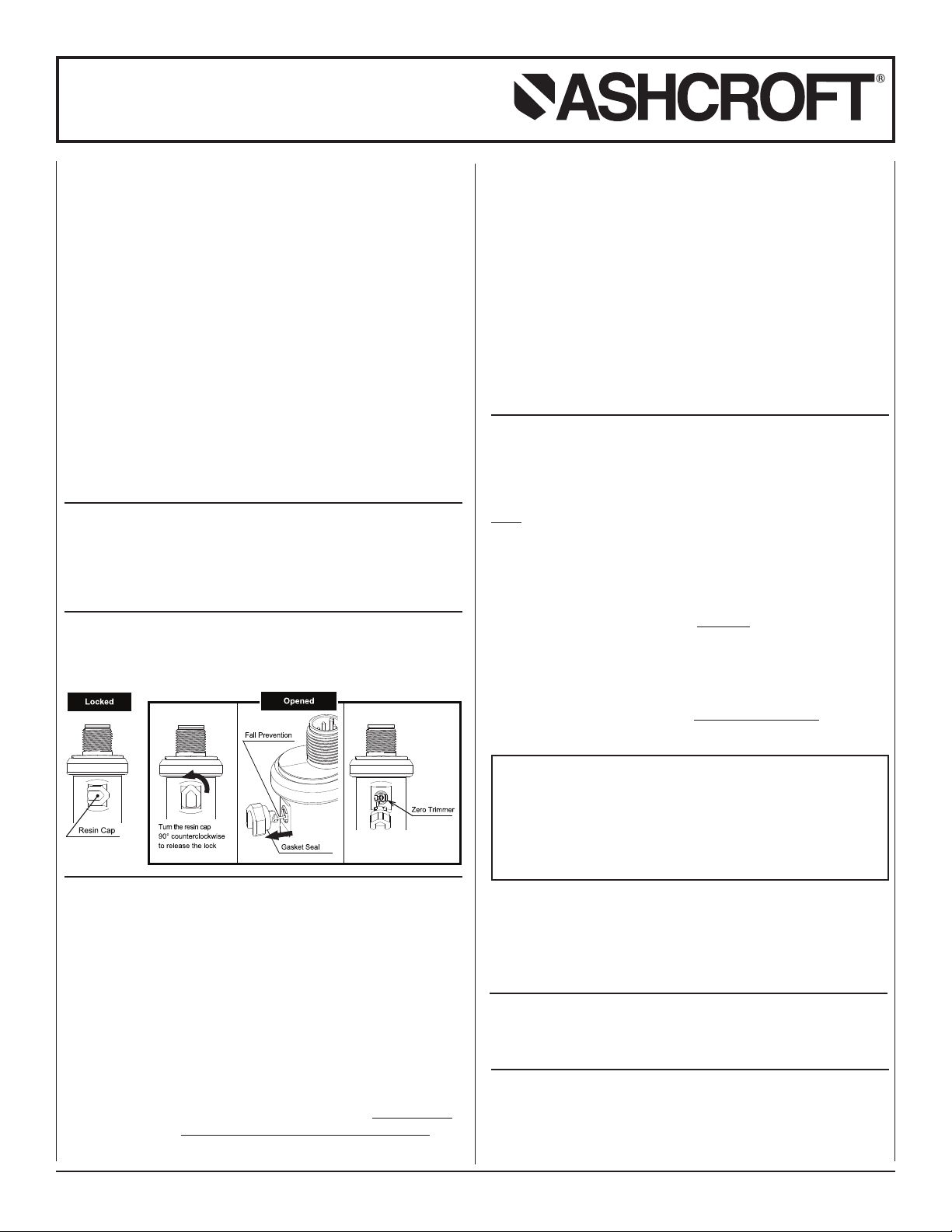
(1) Zero adjustment
Zero adjustment is performed by rotating zero/span adjust-
ment potentiometer shown in the figure (Page 9) with Phillips
screwdriver.
Note: Refer to the following directions as the adjustment
method for absolute and compound ranged products differ.
[Positive pressure range]
Be sure that the applied pressure to the sensor has been
returned to atmospheric pressure (no pressure) state; adjust
the sensor output at this time to 4 mA dc.
[Compound range]
Be sure that the applied pressure to the sensor has been
released to atmospheric pressure (no pressure) state; adjust
the sensor output at this time to the value calculated by the
following:
• Output 4 to 20 mA dc (current output)
[Output mA DC in atmospheric pressure state] = [16 mA dc]
/ ([Upper limit output in range (MPa)] - [-0.1 MPa]) x 0.1 +
[4 mA dc]
e.g. (0.5MPa, Compound range: 6.67 mA dc) / (1.0 MPa,
Compound range: 5.45 mA dc)
(Absolute range)
At vacuum (using a vacuum pump or other means) adjust the
sensor output to the approximate output value based on the
degree of vacuum you are able to achieve. Approximately 4mA
• Avoid putting an excessive load, >44 in. lb.,
10 sec., on the zero adjustment potentiome-
ters as this may result in damage.
m CAUTION:
m CAUTION:
m CAUTION:
m CAUTION:
m CAUTION:
Be sure to recalibrate the device using a set method or reca-
libration standards. Take special care not to effect the explo-
sion-proof performance of the instrument when inspecting in a
hazardous area. The following is a routine inspection checklist
for your reference and use
Routine Inspection Checklist
• Physical appearance (scratches, cracks, warping,
corrosion, etc.)
• Corrosion status of pressure inlet
• Clogging of the air inlet
• Leak test for the connection points and re-tightening of
connecting screw
• Check and tighten all instrument screws
• Insulation resistance between each terminal and case
(at 100MΩ or more/50 Vdc or less)
• Output check by a pressure reference device and measuring
instrument
• Avoid electrostatic discharge.
• Use a soft cloth moistened with water to
only clean the external parts of the instru-
ment. Do not use thinner, benzene, etc.
which cause deterioration and failure.
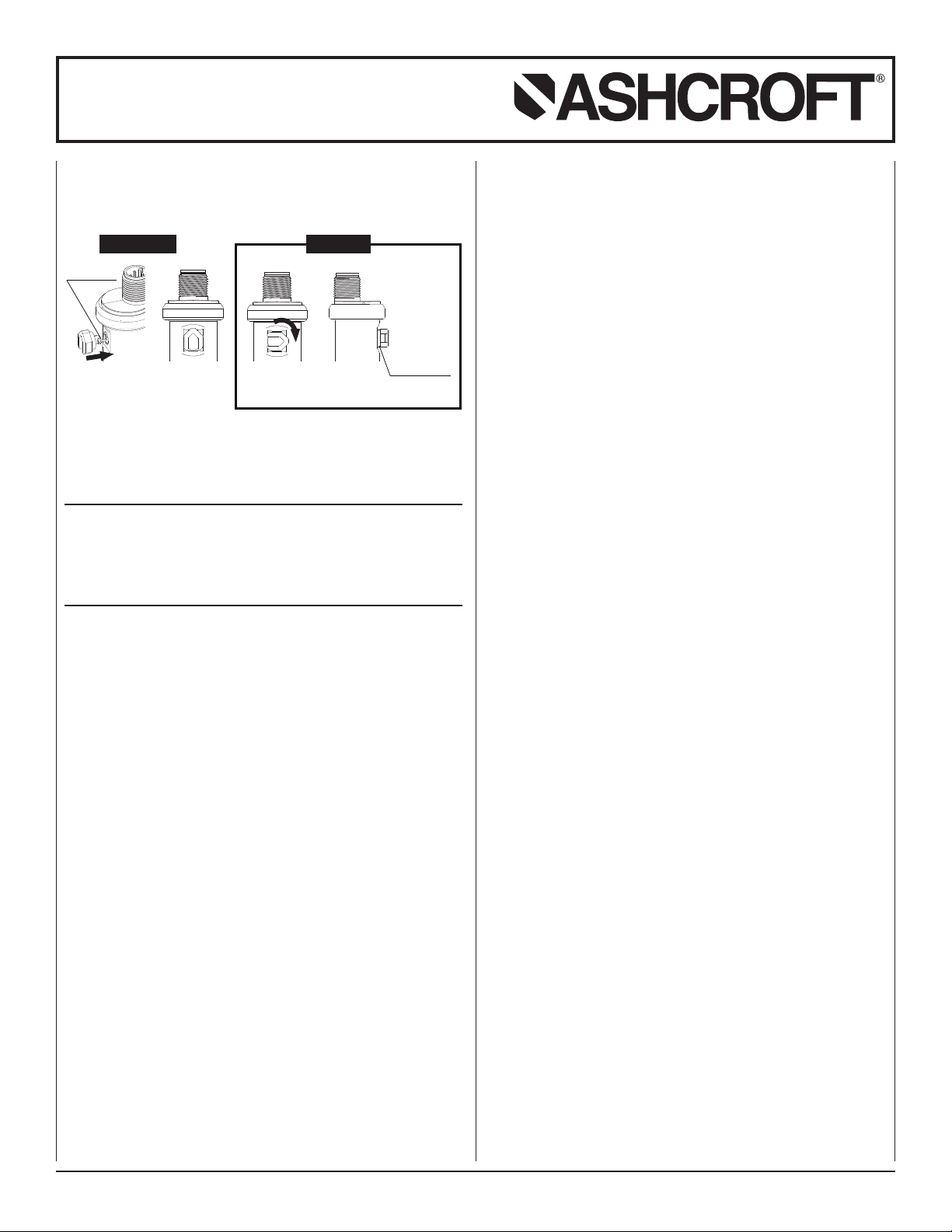
9.2 Adjustment
Remove the rubber plug (tethered plug) mounted at the side of
the enclosure.
• The rubber plug is equipped with a simple
tethering function, however if it is pulled
too strongly, it may be damaged. Please
be careful not to use more force than
necessary [<17 in. lb.].
• Do not attempt adjustments if product is
wet. Do not allow water to enter the product
as this can lead to damage and/or
accidents.
• Make adjustments once the product has
been powered and allowed to warm up for
15 minutes (recommended 30 minutes).