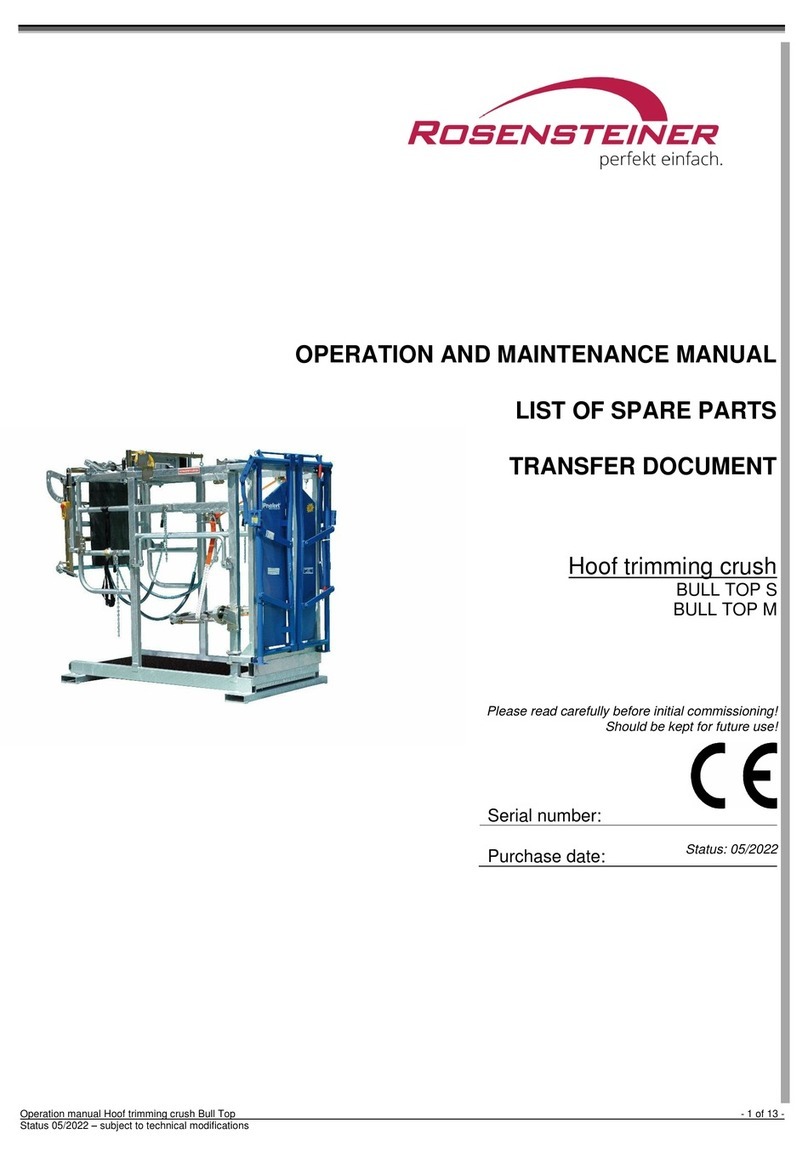
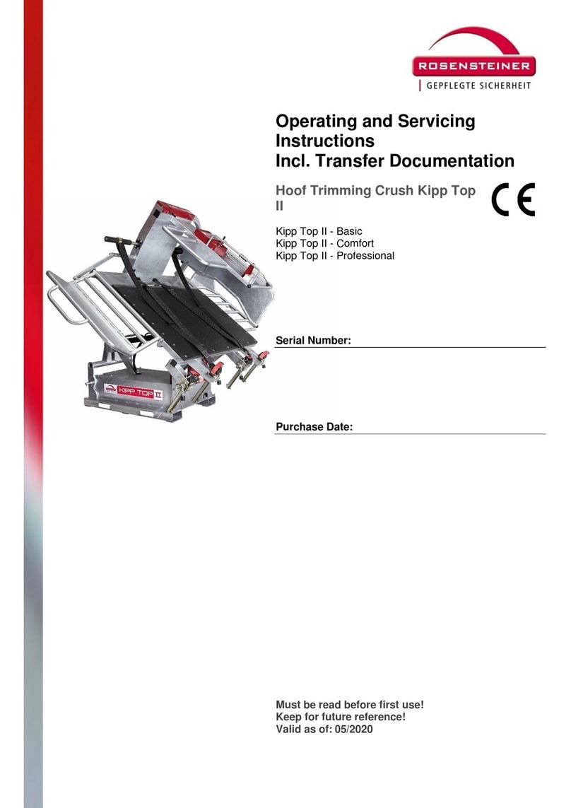
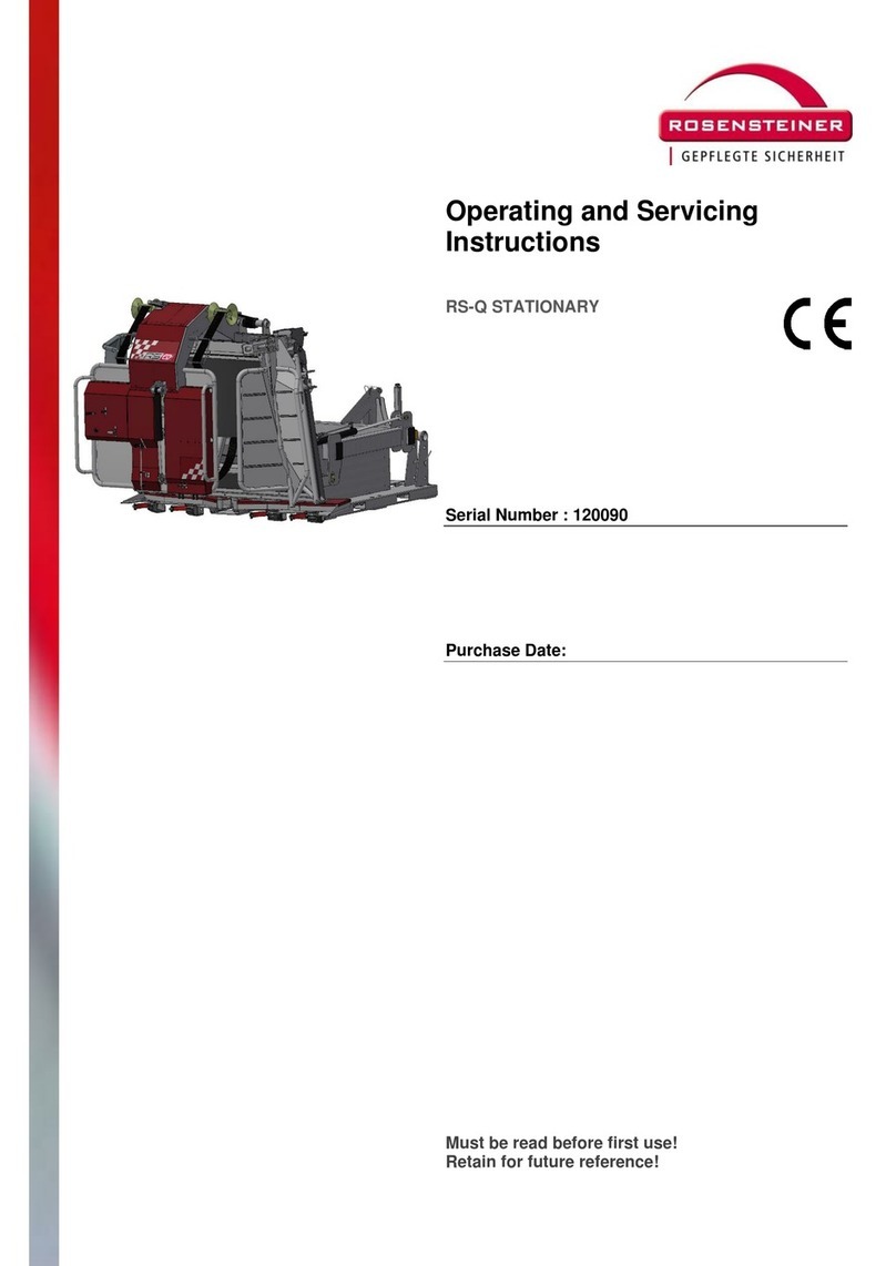
Rosensteiner Red 5 User manual

Operation and
maintenance manual
Red 5 hoof trimming chute
Red 5 –Basic
Red 5 –Comfort
Red 5 –Professional
Serial number:
Date of purchase:
Read this manual before commissioning.
Retain this manual for future reference.
Stand: 01/2022

Operation and maintenance manual
Hoof trimming chute operation manual - 2 von 22 -
Rev.: 01/2022 –We reserve the right to make technical modifications
Contents
1INTRODUCTION.................................................................................................. 3
1.1 Product information ............................................................................................................................ 3
1.2 Intended use........................................................................................................................................ 4
1.3 Examples of improper use ................................................................................................................... 4
1.4 Information on reducing noise and vibrations ..................................................................................... 4
1.5 EC Declaration of Comformity..............................................................................................................5
1.6 Warranty Statement............................................................................................................................ 5
1.7 Specifications....................................................................................................................................... 6
1.8 Type plate............................................................................................................................................ 6
1.9 Operating manual structure and scope................................................................................................6
1.9.1 Document structure ................................................................................................................. 6
1.9.2 Target group............................................................................................................................ 6
1.9.3 Modifications on the operation manual.................................................................................... 7
1.9.4 How to store this operation manual......................................................................................... 7
1.9.5 Space limitations...................................................................................................................... 7
1.9.6 Time limitations........................................................................................................................ 7
1.9.7 Working place for the hoof trimming chute.............................................................................. 7
1.9.8 Erklärung der Informations- und Gefahrenhinweise................................................................ 8
1.9.9 Operating manual and machine safety symbols ..................................................................... 8
2TRANSPORT....................................................................................................... 9
2.1 Transport with tractor on three-point linkage .....................................................................................9
2.1.1 Mounting the hoof trimming chute to a tractor......................................................................... 9
2.1.2 Moving the hoof trimming chute with a tractor....................................................................... 10
2.1.3 Detach the hoof trimming chute from the tractor and park it................................................. 11
2.2 Transport with hand transport device ............................................................................................... 11
2.3 Transport with pallet truck ................................................................................................................ 11
3INSTALLATION / OPERATION ......................................................................... 12
3.1 Device overview / main controls ....................................................................................................... 12
3.2 Safety advice before Installation ....................................................................................................... 14
3.3 Operating the hoof trimming chute ................................................................................................... 15
3.4 Procedure in case of electrical power failure or malfunction ............................................................. 18
3.5 Animal welfare and natural motion sequences.................................................................................. 19
4CLEANING......................................................................................................... 19
5MAINTENANCE / SERVICING / REPAIR.......................................................... 20
5.1 Electricial danger ............................................................................................................................... 20
5.2 Maintenance and care ....................................................................................................................... 21
6SPARE PARTS.................................................................................................. 22
7PERIODIC INSPECTION................................................................................... 22
8SCOPE OF DELIVERY / ACCESSORIES......................................................... 22

Operation and maintenance manual
Hoof trimming chute operation manual - 3 von 22 -
Rev.: 01/2022 –We reserve the right to make technical modifications
1 Introduction
1.1 Product information
Your new Rosensteiner RED 5 hoof trimming chute is a quality product featuring innovative
technology for animal hoof care. This hoof trimming chute is intended to be used for periodic,
qualified, efficient hoof care while enabling the user to assume ergonomic, appropriate, non-
fatigue posture.
For this manual, this hoof trimming chute will also be referred to as the ‘product.’
At the time of marketing, this product and its equipment represent state-of-the-art technology.
However, certain residual risks do remain. We have designed the product to minimise any
user-related health or safety risks which may be caused by such hazards.
This document contains important information on both the safe use of this product and all
required activities such as operation, maintenance or repair work. By following all relevant
instructions, you will help avoid any hazards and increase the service life of the product. You
are not permitted to modify the product in any way.
The documentation provided by our suppliers and, most importantly, the information and
instructions contained therein are fully applicable and should also be followed.
The manufacturer accepts no liability for damage caused by inappropriate action or by failure
to follow the information or instructions as mentioned in the manuals.
While we have taken utmost care to make sure the information within this manual is correct
and up to date, there may be minor discrepancies with regard to its contents. Please advise
us of any such errors.
CAUTION
The manufacturer accepts no liability for any unauthorised (constructional, functional or
process-related) modifications or any use of parts or attachements on the product.
WARNING
Any modifications or alterations made to the product described in this document require a
new hazard analysis and risk evaluation to be performed. The genuine parts and accessories
we offer have been specifically designed for this product. Please note that any parts or
accessories not provided and/or specified by us have not been tested nor approved by us.
Installing and/or using such parts or accessories may negatively affect or restrict the
functionalities this product was originally designed for. The manufacturer accepts no liability
for damage arising from the use of any non-genuine parts or accessories.

Operation and maintenance manual
Hoof trimming chute operation manual - 4 von 22 -
Rev.: 01/2022 –We reserve the right to make technical modifications
1.2 Intended use
The RED 5 hoof trimming chute is solely intended for hoof care work performed on animal
hoofs.
This hoof trimming chute is suitable for cattle weight from 450 kg up to a
maximum of 1000 kg.
Any activities contrary to the product’s intended use are considered improper and, as such,
not permitted. This also applies to the product’s components.
1.3 Examples of improper use
Any operation or use contrary to or going beyond the product’s intended use.
Any use of the product contrary to the safety and hazard requirements or any other
instructions contained in the operating manual. This also applies to errors caused by
poorly executed, improper or unauthorised work performed on the product or while
using the product.
Any modification, by-passing or decommissioning of any product devices ensuring
the product’s correct operation or contributing to active or passive user safety.
Operating the product in a technically incorrect state.
Failure to amend faults affecting user safety before operating the product.
Use of non-permitted auxiliary equipment or tools.
The manufacturer accepts no liability for any damage caused by improper use of the
product!
1.4 Information on reducing noise and vibrations
The maximum emission sound pressure level occurring at the machine is 71 dB(A).
In general, ear protection is recommended, especially when claw care is carried out with disc
grinders.
To reduce vibrations, place the hoof trimming chute on a level surface and, if possible, also
mount it on the ground (for example with the help of concrete anchors).

Operation and maintenance manual
Hoof trimming chute operation manual - 5 von 22 -
Rev.: 01/2022 –We reserve the right to make technical modifications
1.5 EC Declaration of Comformity
Manufacturer and responsible for documentation::
ROSENSTEINER
Landmaschinenbau GmbH
Zehetner 26a
A-4596 Steinbach / Steyr
Telefon +43(0)7257/7071
declares that the following product:
Type: RED 5 Basic
RED 5 Comfort
RED 5 Professional
Bezeichnung: Klauenpflegestand RED 5
Fabrikat: Rosensteiner
as described in the attached operating manual, complies with the provisions set forth in the
2014/35/EU Machinery Directive.
Steinbach, den 30.03.2021
Andreas Rosensteiner, Inhaber
1.6 Warranty Statement
Rosensteiner Landmaschinenbau GmbH grants the purchaser a product warranty in
accordance with the following provisions:
•The warranty shall cover the product’s functionality and quality. No warranty is
granted for signs of wear.
•The warranty period is 2 years, beginning at the date of delivery to the customer. The
manufacturer considers any warranty claims received by the dealership or by our
factory (Zehetner 26a, A-4596 Steinbach, Austria) within the warranty period.
•If within the warranty period the product suffers any defects in material or
workmanship, the customer shall immediately assert the relevant warranty claims with
their dealership or manufacturer.
•The customer shall present the defective device or part to the dealership. Any
subsequent repair or replacement work may not be performed without the approval
from Rosensteiner. The manufacturer will not incur any expenditure without their
express consent. Any defective parts shall be stored at the dealership or sent to
Rosensteiner as agreed: The customer has to bring the device to the dealer freight
paid.
•Warranty claims cannot be accepted if the device is damaged or destroyed by force
majeur. Caution: Please note that warranty claims are not accepted for damage
caused by improper use, overload, attaching the product to carrier vehicles of
disproportionate size, or failure caused by not paying attention to maintenance work!
•Warranty can just be accepted when the device is presented along with the purchase
contract, invoice or delivery note as well as the device serial number.
•The warranty is performed in a way that the device is repaired or replaced by a
functional equivalent.

Operation and maintenance manual
Hoof trimming chute operation manual - 6 von 22 -
Rev.: 01/2022 –We reserve the right to make technical modifications
•Any further claims, particularly damage or loss caused by the regular use and/or
operation of the devices are not accepted.
•Provided that we replace the device or product in question under this warranty, any
warranty claims against the selling dealership are not excluded.
1.7 Specifications
Machine Type RED 5 hoof trimming chute
Dimensions 2450(2300)/1220/2200 (L/W/H)
Recommended animal weight 450-1000 kg
Product weight 625-725 kg
Attachment pallet truck, forklift truck (both sides)
preparation for manual transport devices
preparation for 3-point linkage
Frame surface galvanised, powder-coated
1.8 Type plate
The type plate is attached on the left side of the head catching wing.
1.9 Operating manual structure and scope
1.9.1 Document structure
This operating manual was created in accordance with the 2014/35/EU Machinery Directive
and the relevant MSV 2010 machine safety regulation applicable in Austria. This operation
manual will help you become familiar with the product’s technical details, enabling you to
properly operate and maintain the product in a safe way and make use of its intended
applications.
1.9.2 Target group
The operation manual is intended for people who are familiar with the handling of a hoof
trimming chute, with the commissioning and operation of such and have the appropriate
qualifications for their activities and functions, i.e. who, based on their technical training, their
knowledge and experience, can assess and evaluate the work identify potential hazards.
Every person who works with this hoof care device must be familiar with the handling of the
animals/cattle to be treated.
Every person working with this machine (e. g. operation, servicing, transport) has to:
•Read and understand this operating manual before working on the machine.
•Follow all instructions and safety guidelines contained in the manual.

Operation and maintenance manual
Hoof trimming chute operation manual - 7 von 22 -
Rev.: 01/2022 –We reserve the right to make technical modifications
1.9.3 Modifications on the operation manual
This operation manual represents the design of the product at the time of creating this
operating manual.
1.9.4 How to store this operation manual
Always keep this operating manual in the same location where the product is operated. The
manual should be accessible any time for any person associated with the work performed
using the product. If this manual is lost, please contact your dealership for a replacement
manual. If you decide to re-sell your hoof trimming chute, please remember to pass this
operating manual on to its new owner. The manual is a legally required component of the
machine. This operating manual is ready for download at www.rosensteiner.at.
1.9.5 Space limitations
The product is designed for both stationary and mobile use at various locations.
1.9.6 Time limitations
Due to the mechanical strain acting on the product during use, periodically check the
components for reliability, susceptibility to failure and limits of use over the product’s service
life.
The following phases in service life are not covered in this operating manual:
•Manufacture and transport (to the customer/user)
•Service work on the product and its components as performed in workshops
•Any work requiring the qualification and skill levels of the person performing the work
(e. g. welding, electrical work, …).
1.9.7 Working place for the hoof trimming chute
Recommended space requirements for the Red 5:

Operation and maintenance manual
Hoof trimming chute operation manual - 8 von 22 -
Rev.: 01/2022 –We reserve the right to make technical modifications
1.9.8 Erklärung der Informations- und Gefahrenhinweise
Any additional information provided in this manual is identified by the above information
symbol.
SIGNAL WORD
Identifies the type and source of the hazard and any associated risks.
Potential consequences for people, machine parts, tools and work pieces (residual risk).
Action taken to avoid the danger to life and to reduce any residual risks.
SIGNALWORD
Explanation
NOTE
Indication of a potentially harmful situation which may result in damage to the equipment or
nearby property.
CAUTION
Indication of a potentially dangerous situation which may result in minor injury or property
damage.
WARNING
Indication of a potentially dangerous situation which may result in major injury or death.
DANGER
Indication of an immediate danger which will result in major injury or death.
1.9.9 Operating manual and machine safety symbols
Never stand between the implement and the tractor.
Crushing hazard!
Read and follow the operating manual and all safety instructions before use!
Stop the engine and disconnect power before performing any repair, maintenance or
cleaning work.
Keep a safe distance to high-voltage power lines.!

Operation and maintenance manual
Hoof trimming chute operation manual - 9 von 22 -
Rev.: 01/2022 –We reserve the right to make technical modifications
Before disconnecting or parking the machine use chocks to prevent it from rolling off.
Avoid bumpy terrain or slopes which may cause the device to slip, tip over or overturn.
2 Transport
Three different possibilities are provided for changing the location of this hoof trimming chute.
Other variants that deviate from the ones described offer a high potential of danger and are
not permitted!
2.1 Transport with tractor on three-point linkage
The following describes the procedure for transporting the hoof trimming chute with a tractor
and the risks to be observed.
The three-point hitch on the hoof trimming stand is not fitted as standard.
2.1.1 Mounting the hoof trimming chute to a tractor
To transport the hoof trimming chute with the tractor, the head catch must first be brought
into the catching position (power supply necessary!).
Lower linkage Cat. II is achieved when the catching
doors are almost parallel to the outer bars of the
ground.
Then the chute is attached to the lower link of the
tractor's hydraulics using the optional lower link pins
and to the upper link mount of the tractor using the
optional 3-point linkage chain. At least two chain links
must hang down inwards on the chain slots in which
the chain is suspended on the claw care stand!
WARNUNG
Reverse the tractor to the chute, making sure that there are no persons in the danger zone
between the tractor and the chute!

Operation and maintenance manual
Hoof trimming chute operation manual - 10 von 22 -
Rev.: 01/2022 –We reserve the right to make technical modifications
Take care when mounting:
Before attaching the hoof trimming chute make sure the front of the tractor is
sufficiently ballasted and the parking brake is locked.
Never step between the tractor and the hoof trimming chute when attaching the
product - crushing hazard!
Use suitable locking pins to mount the hoof trimming chute to the lower links and top-
link chain.
When operating the tractor’s hydraulic system (top and lower links), make sure the
tractor is stable. Keep a safe distance to any hazardous moving parts. Never step on
any parts of the tractor (lower links, ...) or on the hoof trimming chute.
Never step between the hoof trimming chute and the tractor while the tractor is
running.
WARNING
Check transport position:
The front leg winch must be swinged inwards and all safety ropes must be fastened in
the bollard clamps..
The service arm and cable must be brought into the transport position and fixed with
the catch at the stop.
The hind leg retention bracket must be swinged to the lowest lockable position.´
2.1.2 Moving the hoof trimming chute with a tractor
WARNING
When transporting, keep a sufficient distance from electrical high-voltage cable
When transporting on public roads, observe the road traffic regulations of your
country and attach the legally prescribed lights or warning signs to the chute
Maximum speed when transporting the chute is 25 km/h.
When driving during the day, two warning plates must be attached to the rear of the
chute on the left and right so that the rear lighting of the tractor is not obscured. When
driving at night, a lighting strip with complete lighting (lamps on the left and right as on
the tractor) must be fitted to the rear of the chute.

Operation and maintenance manual
Hoof trimming chute operation manual - 11 von 22 -
Rev.: 01/2022 –We reserve the right to make technical modifications
2.1.3 Detach the hoof trimming chute from the tractor and park it
To park the hoof trimming chute take care of:
WARNING
Drive onto a level parking space.
Secure tractor against rolling (handbrake, brake wedge).
Lower the hoof trimming chute. When parking the hoof trimming chute, make sure
that it cannot tip over or slip, especially if it is placed in an elevated position on
stacks, pallets, etc.
First loosen the upper link chain, then the lower link.
2.2 Transport with hand transport device
The lifting axle incl. the hand transport wheels are
not included in the scope of delivery as standard!
This variant is used exclusively for establishing the
end position of the implement before claw care, not
for general transport over longer distances!
First secure the service arm and cable feed
and swing in the front leg winch!
Engage the ball of the lifting axle in the hole
provided and lift the claw care stand with
the crank.
Insert the push-on wheels and turn the lock.
Place the unit with the wheels back on the ground by pushing the lifting axle towards
the unit!
Place the lifting axle on the opposite side, lift it up and drive.
-The lifting axle develops a strong pull in the direction of the implement as soon
as the lifting axle is pressed above the centre point!
Hold the axle firmly and support yourself if necessary to avoid injuries!
-Never place hands and feet under the chute - risk of crushing!
2.3 Transport with pallet truck
-Serves exclusively to establish the end position of the unit before hoof care and to
load the hoof trimming chute.
-Front and rear transport possible
-Ensure that the forks are sufficiently long and that there is an increased risk of
tipping over the chute!

Operation and maintenance manual
Hoof trimming chute operation manual - 12 von 22 -
Rev.: 01/2022 –We reserve the right to make technical modifications
3 Installation / Operation
3.1 Device overview / main controls
Variant Basic/Comfort:
Ref. Description Ref. Description
01 Pressure roller safety crank 02 Hind leg retention bracket Basic/Comfort
03 Head catch control 04 Front foot strap
05 Locking rod 06 Rear leg winches (1 piece. at Basic)
07 Ankle strap 08 Knee rope
09 Rope clamp 10 Rear foot strap
11 Front leg winch 12 Switchbox
13 Head catch 14 Belly strap
15 Rubber mat 16 Mounting holes for hand transport wheels
17 Front leg winch control 18 Power connection
19 Service arm 20 rear leg winch control
21 Pressure roller safety crank 22 Idler pulley
23 Winding shaft
23

Operation and maintenance manual
Hoof trimming chute operation manual - 13 von 22 -
Rev.: 01/2022 –We reserve the right to make technical modifications
Variant Professional:
Ref. Description Ref. Description
01 Pressure roller safety crank 02 Hind leg retention bracket Professional
03 Head catch control 04 Front foot strap
05 Locking rod 06 Rear leg winches
07 Ankle strap 08 Knee chain with protective hose
09 Electr. belly strap control 10 Rear foot strap
11 Front leg winch 12 Switchbox
13 Head catch 14 Belly strap
15 Rubber mat 16 Mounting holes for hand transport wheels
17 Front leg winch control 18 Power connection
19 Service arm 20 Rear leg winch control
21 Belly strap winch 22 Belly strap arm
23 Winding shaft
1
2
3
4
5
6
7
8
9
10
11
12
13
14
15
16
17
18
19
20
22
21
23

Operation and maintenance manual
Hoof trimming chute operation manual - 14 von 22 -
Rev.: 01/2022 –We reserve the right to make technical modifications
3.2 Safety advice before Installation
NOTE
When installing the product, ask for the assistance of a person experienced in using
the hoof trimming chutes.
Never trim hoofs immediately after feeding the cattle!
WARNING
Read and follow the instructions in this operating manual before installing and
operating the product.
The product should only be operated by persons familiar with the intended application
and the correct handling of cattle.
Before operation, visually check the hoof trimming chute for any defects.
Ensure that the hoof trimming chute is placed on an even surface.
Check the hoof trimming chute for loose bolts or other parts.
Check belts and ropes for wear.
Check the condition of all protective devices.
Check the screw connections and retighten it if necessary.
The hoof trimming chute may only be operated with suitable protective measures
against excessive contact voltage. Earth leakage circuit breaker interrupts at 30mA.
The power supply to the chute must contain an electrical neutral conductor.
(Sockets and any intermediate cables too)
A maximum total power of 1.9 kW is permitted at the sockets of the service arm
(19)! Therefore, pay attention to the power consumption of your connected
devices (e.g. disc grinders).
If the thermal protection fuse interrupts the power supply to the head catching or the
front leg winches, the head catching can still be opened or the front leg winches can
still be lowered. After waiting for approx. 3 to 5 minutes, all motors can be operated
again in both directions.
Visually inspect the electrical equipment for damage.
Check whether the electrical inspection is within the annual interval. (annual
inspection of the electrical installation by an expert is required).
Check the work area and ensure no other unauthorised persons are present. This
particularly applies to children.
Use suitable personal protective equipment.

Operation and maintenance manual
Hoof trimming chute operation manual - 15 von 22 -
Rev.: 01/2022 –We reserve the right to make technical modifications
3.3 Operating the hoof trimming chute
For subsequent numbering see device overview(s)
1) Place the hoof trimming chute on a level, easily accessible place with a non -slip floor. For
freestall barn animals, the use of pushing gates is highly recommended!
2) All parts protruding into the chute must be swinged or cleared out of the inner area. The
rear hind leg retention bracket (2) must be swinged up and the belly strap (14) must rest
on the rubber mat at the bottom. For variants Basic and Comfort, hook the side barrier
chain tightly to the side of the head catching doors (13).
3) Release the emergency stop switch on the head catch control
(3).
4) Check whether the direction of rotation of the front leg winch
(17) is correct (arrows on the button indicate the direction of
correct rotation). If this is not the case, correct the direction of
rotation by switching the phase inverter at the power
connection (18).
5) Bring the head catch in catching position (head catching doors
and frame parallel to the ground) using the "Auf" (Open) and
"Zu" (Close) buttons on the head catch control (3).
6) Drive the cattle in the chute, preferred using pushing gates.
7) Close the head catch with the "Zu" (Close) button on the head
catch control (black button (3)), the head catch stops
automatically at 160 mm safety width! For animals with a very
wide neck, the safety catch must be stopped earlier to avoid
squeezing the animal! Additional positioning disc with 210 mm
catching width included in delivery! If necessary, have it
mounted by competent personnel!
The animal should be as close as possible to the neck frame
with its shoulders. Check that the head is securely fixed. Do
not squeeze the neck area! If necessary, open the safety catch
slightly!
8) Fixing the animal in the chute:
Basic/Comfort:
Place the knee rope (8) horizontally at the height of the knee
joint, tighten it as much as possible and fasten it to the bollard
clamp (9) according to the sticker.
Professional:
There is no need to put on the knee rope, as the integrated
knee chain (8) of the hind leg retention bracket (2) takes over
this function.
Pull the lever on the left side of the hind leg retention bracket
(2) and swing it to the appropriate working height or push it as far as
possible towards the cow. When the lever is released, the hind leg
retention bracket locks automatically.
The hind leg retention bracket (2) must be fully locked on both sides!

Operation and maintenance manual
Hoof trimming chute operation manual - 16 von 22 -
Rev.: 01/2022 –We reserve the right to make technical modifications
9) Putting on the securing elements:
Basic/Comfort:
Hang the belly strap (14) on the idler pulley (22), pull the strap
tightly by hand through the winding bolt and tighten it with the
DS crank (21) 1-2 turns clockwise. This belt prevents the
animal from going down in the chute. Do not lift the animal off
the ground!
Fasten the rear leg above the hock with the help of the ankle
strap (7) and secure it by slightly tightening the rope of the rear
leg winch(es) (6). Secure the second rear leg in the variant
Comfort as well.
Professional:
Put on the belly strap (14) by pressing the button (9).
As far as the belly strap encloses the animal’s chest tightly.
This belt prevents the animal from falling to the ground in the
chute. Do not lift the animal off the ground!
Fasten both rear legs above the hock with the help of the ankle
strap and secure them by slightly tightening the rope of the
rear leg winches (6).
10) Lifting a rear leg:
Basic/Comfort:
Swing the hind leg retention bracket down to the appropriate
working height and lock the position in the locking rod (5).
Lift the rear leg close to the V-Shape. Pay attention to the
optimal tension of the knee rope (8)
Professional:
Lift the rear foot close to the V-shape. Pay attention to the
optimal tension of the knee chain (8). The tension of the knee
chain can be adjusted by hand.
11) Fixing a rear foot.
Place the foot strap (10) above the dewclaw once around the
rear foot and hang the end of the foot strap on the holding
mushroom on the winding shaft (23). (see picture right side)
With the help of a few turns of the DS crank (1) pull the rear
foot into the V-shape so that it lies firmly in it.

Operation and maintenance manual
Hoof trimming chute operation manual - 17 von 22 -
Rev.: 01/2022 –We reserve the right to make technical modifications
12) Fixing a front foot:
Attention! Always work on a front foot only when the
rear foot is secured on this side!
Place the front foot strap (4) between the claw and the
dewclaw.
Swing the front foot holder in until the foot is between the
two plastic winding bodies. Hook in the small bolt of the foot
belt between the plastic winding bodies and wind up the
foot electrically ((17) black button). Do not overwind the
animal's foot - risk of injury to the animal!
Swing out the front foot holder (11) until the claw is outside
the main frame and thus easily accessible.
Perform hoof care
Swing the foot holder back into the frame and then lower
the leg. This gives the animal a better balance.
Press the green button (17) to release and remove the front
foot strap (4). Swing out the foot holder completely to the
front.
13) After the claw care, loosen all fasteners and securing
elements, the head catch at the end!
14) Open the head catch using the green button on the control
panel (3).
15) Disc grinders may only be used with protection!
16) It is only allowed to put the disc grinder in the grinder holder
on the service arm (19) after the wheel has come to a
complete standstill!
17) When the hoof trimming chute is not in operation, the
emergency stop switch (red) at the head catch control (3) must
be pressed!
All work has to be done sideways, never bend under the body, in front of or behind the
feet of the animal!

Operation and maintenance manual
Hoof trimming chute operation manual - 18 von 22 -
Rev.: 01/2022 –We reserve the right to make technical modifications
3.4 Procedure in case of electrical power failure or malfunction
If, during the use of the hoof trimming chute, there is a electrical power failure on the power
supply side or a malfunction on the device, so that it is not possible to put down the safety
elements and release the animal within a time that is not harmful to the animal, proceed as
follows:
NOTE
Head catch:
To unlock the head catch on the left and right,
remove the screws and take out the cans.
Manually pull the two wings of the head catch
on the left and right outward and free the
animal.
NOTE
Front foot winches:
Remove the screws of the outer plastic winder body and pull
the winder body off the shaft.
Remove the front foot strap and free the front foot.
NOTE
Rear leg winch:
If possible, unhook the ankle strap from hook on one side.
In a time-critical emergency, cut the rope.
NOTE
Electric belly strap system (Professional):
If possible, remove the idler pulleys on the left and right
of the head catch, unhook the rope and then loosen the
link on the chest strap. Caution! Rope may be under
tension! In a time-critical emergency, cut the rope.

Operation and maintenance manual
Hoof trimming chute operation manual - 19 von 22 -
Rev.: 01/2022 –We reserve the right to make technical modifications
3.5 Animal welfare and natural motion sequences
Take care not to cause pain or injury to the cattle by unnatural movements. This is especially
true when lifting the feet and swinging out the front feet.
To make it easier to understand, an overview of the entire musculoskeletal system is
included in the operating manual. The most important points are marked (picture below).
The securing elements belly strap and ankle strap serve to secure the animal so that it
cannot fall to the ground. Don’t let the animal hang in the straps for a long time, as this can
cause paralysis with permanent consequences. If the animal gets caught in the harnesses,
the work must be interrupted immediately, and the animal must be brought back to its feet by
taking appropriate measures. If the animal does not react to this, you must loosen all foot
attachments, lower the animal to the ground and, if necessary, open the head catch.
4 Cleaning
NOTE
Observe the safety instructions in the safety data sheet of the cleaning / disinfecting
agents!
Dispose of cleaning waste water according to the regulation in the country of use!
Wear safety glasses!
•Do not spray or jet water (high-pressure cleaner) onto electrical components!
Elbow joint
Elbow joint
Fetlock joint
Ankle Joint
Knee Joint
Hip Joint

Operation and maintenance manual
Hoof trimming chute operation manual - 20 von 22 -
Rev.: 01/2022 –We reserve the right to make technical modifications
5 Maintenance / Servicing / Repair
WARNING
Maintenance work may only be performed by qualified and trained personnel or by
the manufacturer itself.
Maintenance and repair work may only be carried out if suitable lighting is available
for the work to be carried out.
DANGER
Maintenance work may only be carried out when the machine is shut down.
5.1 Electricial danger
DANGER
Contact with energized parts.
Effects of electric current on humans
Compliance with legal requirements for installation, operation, maintenance and
testing of electrical equipment.
Work may only be carried out by qualified electricians!
Damaged installations must be repaired immediately by qualified personnel!
Use of suitable plugs, couplings!
Recurring tests!
Before opening electrical equipment housings, it is essential to disconnect them from
the power supply and secure them against being switched on again!
The maintenance personnel must be familiar with all technical standards and rules!
Other manuals for Red 5
1
Table of contents
Other Rosensteiner Farm Equipment manuals

Rosensteiner
Rosensteiner RED Q Guide

Rosensteiner
Rosensteiner 901557 User manual

Rosensteiner
Rosensteiner Kipp Top II Basic User guide

Rosensteiner
Rosensteiner RS-Q STATIONARY User guide

Rosensteiner
Rosensteiner Red 5 User manual

Rosensteiner
Rosensteiner BULL TOP S User manual

Rosensteiner
Rosensteiner VET PRO STATIONARY User guide