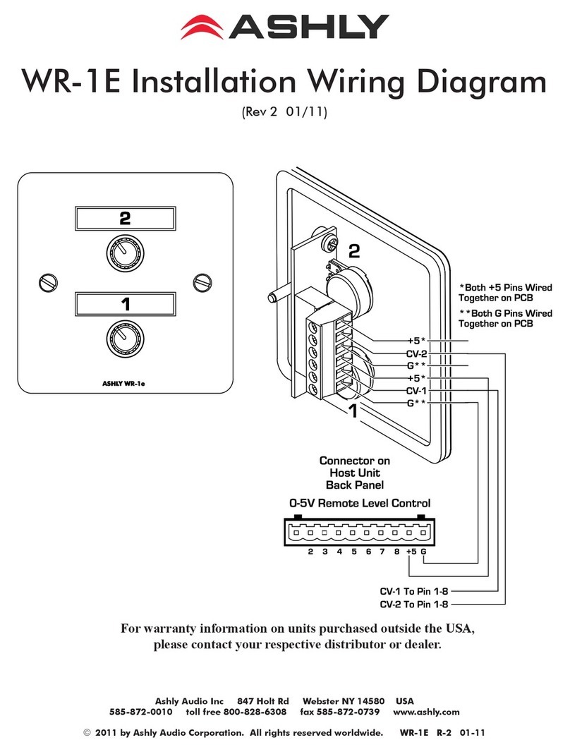
Ashly VCX-80 User manual

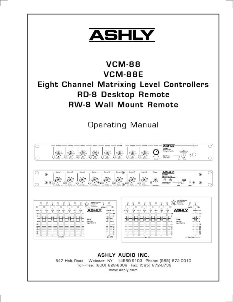
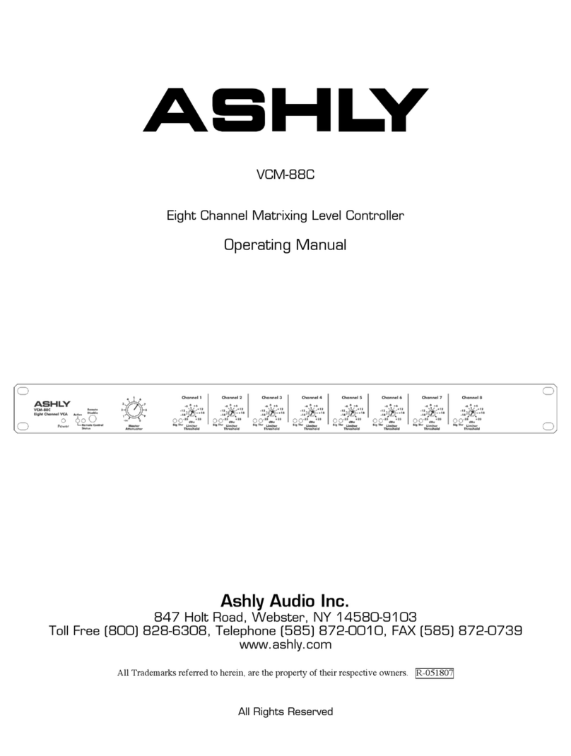
VCX-80
Eight Channel VCA/Limiter
RD-8/RW-8
Digital Remote Controller
Operating Manual
ASHLY AUDIO INC.
847 Holt Road Webster, NY 14580-9103 Phone: (716) 872-0010
Toll-Free: (800) 828-6308 Fax: (716) 872-0739 Internet: http://www.ashly.com/

2
Operating Manual - VCX-80 Master VCA/Limiter, RD-8 and RW-8 Remote Controller
Table Of Contents
1 INTRODUCTION ..........................................................3
2 UNPACKING .............................................................3
3 ACPOWERREQUIREMENTS ..............................................3
4 SECURITYCOVERS .......................................................3
5 CONTROLS-VCX-80 ......................................................4
5.1 Limiter Threshold ........................................................4
5.2 Master Attenuation .......................................................4
5.3 Remote Active Indicator ...................................................4
5.4 Remote Disable Switch....................................................5
5.5 Power Switch............................................................5
6 CONTROLS-RD-8/RW-8 ...................................................5
6.1 Channel Or Master On Switch ..............................................5
6.2 Channel Or Master Fader ..................................................5
6.3 Remote Disable Indicator ..................................................5
7 CONNECTIONSANDCABLES .............................................6
7.1 Balanced vs. Unbalanced Audio Connections. . . . . . . . . . . . . . . . . . . . . . . . . . . . . . . . . . .6
7.2 Inputs..................................................................6
7.3 Channel Outputs .........................................................6
7.4 Master Output ...........................................................6
7.5 Digital Connection - VCX-80...............................................6
7.6 Digital Connection - RD-8/RW-8 ............................................7
7.7 DC Control Voltage Connection .............................................7
8 APPLICATIONS ...........................................................8
8.1 Remotely Controlled 8-Channel Mic Mixer . . . . . . . . . . . . . . . . . . . . . . . . . . . . . . . . . . . .8
8.2 Remote Control of Stereo Sources ...........................................8
8.3 Remotely Controlled Stage Monitor Mix . . . . . . . . . . . . . . . . . . . . . . . . . . . . . . . . . . . . . .9
8.4 Master Control Of Large Distibuted Sound System . . . . . . . . . . . . . . . . . . . . . . . . . . . . . .9
8.5 DC Remote Control.......................................................9
9 CHANGINGFACTORYCONFIGURATIONS ................................10
10 TROUBLESHOOTINGTIPS................................................10
11 WARRANTYINFORMATION ..............................................11
12 DIMENSIONALDRAWINGS ..............................................11
13 TECHNICALSPECIFICATIONS ...........................................12
14 SCHEMATICDIAGRAMS .................................................13

3
Operating Manual - VCX-80 Master VCA/Limiter, RD-8 and RW-8 Remote Controller
1.INTRODUCTION
One of the many useful circuits to be developed for
audio use is the VCA, or voltage controlled amplier. A VCA
circuit allows for accurate, low distortion level control with-
out signal degradations sometimes encountered when using
mechanical controls or long signal paths. VCA circuits can
be found in compressor/limiter/expanders, noise gates, noise
reduction systems, automatic mixers, VCA-Bus consoles, and
other places where remote control or fast automatic system
response is required. Designers at Ashly felt there was still a
need for high quality VCA control which could be incorporated
into professional sound systems without unnecessarily high
cost or complication.
The Ashly VCX-80 contains eight fully-independent
VCA channels in a single unit capable of limiting, remote
level control, and mixing. By itself, the VCX-80 functions as
a precise eight-channel limiter with recessed threshold adjust-
ments on each channel. When connected to the Ashly RD-8
Remote Controller, DC control, or even computer control, the
VCX-80 can control individual channel and master levels with
a range of +20dB to -75dB. Each VCA channel comes con-
figured with separate input and output jacks for patching into
line-level signal paths, and can be reconfigured to use single
jack TRS insertion for easily patching into mixing consoles.
The VCX-80 has a master output jack providing a
summed output of all eight channels, allowing the unit to
function as a fully-contained eight-channel remote controlled
line level mixer. DC control of channel and master level uses
a simple potentiometer circuit connected to a dedicated con-
nector on the rear of the unit.
The RD-8 remote controller is a compact slide-fader
remote level controller which can be desk-top situated or
rack-mounted into two rack spaces (3.5 inches) using the
RD8-RM optional mounting bracket. This remote controller
is also available as the RW-8 for wall-mounting into a standard
4-gang electrical box. The RD-8 controls the audio levels of
the VCX-80 digitally over a standard XLR snake cable or mic
cable. The RD-8 is powered entirely by the VCX-80 over the
XLR data cable.
The RD-8 can communicate to the VCX-80
over a 24 gauge snake cable in excess of 1/4 mile. The RD-8 also
pulse-shapes the digital waveform to eliminate digital crosstalk
noise into adjacent audio channels.
2.UNPACKING
As a part of our system of quality control, every Ashly
product is carefully inspected before leaving the factory to
ensure flawless appearance. After unpacking, please inspect
for any physical damage. Save the shipping carton and all
packing materials , as they were carefully designed to reduce
to minimum the possibility of transportation damage should
the unit again require packing and shipping. In the event that
damage has occurred, immediately notify your dealer so that
a written claim to cover the damages can be initiated.
The right to any claim against a public carrier can
be forfeited if the carrier is not notified promptly and if the
shipping carton and packing materials are not available for
inspection by the carrier. Save all packing materials until the
claim has been settled.
3.ACPOWERREQUIREMENTS
A standard IEC-320 AC inlet is provided on the
rear panel of the VCX-80 to accept the detachable power
cord shipped with the unit. Units distributed within the
United States are preselected for 120VAC, 60Hz and should
be plugged into a standard NEMA 5-15 3-wire grounded AC
receptacle. Most units distributed outside the US are prese-
lected and labeled for 240VAC, 50-60Hz and are shipped with
the appropriate power cord.
The VCX-80 will perform normally from 98 to 125
volts AC. An internal line fuse is used. In the event of fuse
failure, refer to a qualified service technician for servicing.
Power consumption of the VCX-80 is 18 watts.
4.SECURITYCOVERS
For installations where it is desirable to protect the
front panel controls from tampering or accidental misadjust-
ment, use the Ashly security cover, which is available in both
single and double rack space sizes. Installation is simple and
does not require removal of the equipment from your rack.
See your Ashly dealer for details.
Ashly Security Cover

4
Operating Manual - VCX-80 Master VCA/Limiter, RD-8 and RW-8 Remote Controller
5.CONTROLS-VCX-80
5.1 Limiter Threshold
This recessed trimpot adjusts the signal threshold above
which the limiter will become active. The units of this threshold dial
are dBu where 0dBu = 0.775Vrms. The limiter is a peak-detecting
true VCA-type limiter with very low distortion. The input to output
ratio of the limiter is approximately 10 to 1 with a relatively fast
attack and moderate release time behavior. The adjacent yellow
threshold LED indicates when the limiter circuit has been activated
by an audio signal above the threshold level. To disable the limiter
on any given channel, simply rotate its threshold adjustment fully
clockwise to +23dBu, which is the maximum input signal of the unit.
5.2 Master Attenuation
This control attenuates all eight channels uniformly.
This control was designed as a simple means of turning-down
all eight audio channels at the VCX-80 location in the event
of feedback or other sound system problems. Normally this
control should be set fully clockwise at 0dB attenuation.
5.3 Remote Active Indicator
This green LED indicates when the VCX-80 is receiving
data from the RD-8 or RW-8. If this light goes out, it means the
VCX-80 is no longer receiving data, due to a disconnection of
the control data signal. In the event of remote control data inter-
ruption, the VCA channel levels will "remember" their settings
just before the data reception stopped and continue to operate as if

5
Operating Manual - VCX-80 Master VCA/Limiter, RD-8 and RW-8 Remote Controller
there were no changes happening. Reconnecting the remote data
signal with the VCX-80 still operating will silently but instantly
change the channel level settings to wherever the controller is
currently set. If the VCX-80 AC power is switched on with no
data reception, all eight channels and the master level will be set
to unity gain (0dB).
5.4 Remote Disable Switch
This switch disables the RD-8 remote controller and
returns all eight channels to unity gain. The adjacent red LED
indicates when this switch is depressed. The nearby green Re-
mote Active indicator will go off when the remote is disabled
because the RD-8 does not send any data when it is disabled.
After releasing the remote disable switch, all channels return
to their respective levels set by the RD-8 remote controller.
5.5 Power Switch
This front-panel push-button switches the AC power
to the unit. The adjacent green LED indicates when the unit is
powered on. If the green LED does not light, check to see if
the unit is plugged into a live outlet. If there is still no light,
refer the unit to a qualified service technician for possible fuse
replacement.
6.CONTROLS-RD-8
The RD-8 and RW-8 are functionally the same. The difference is that the RW-8 is designed to mount as a wall plate using a
standard 4-gang electrical box.
6.1 Channel or Master On Switch
These push-buttons switch the respective VCX-80 channel on or off. When switched on, the channel gain is controlled by the
setting of the respective channel fader on the RD-8. When switched off, the respective VCX-80 channel is muted to approximately
-75dB by the internal VCA circuit. The adjacent green LED is lit when the channel is switched on.
6.2 Channel or Master Fader
These slide faders control the gain (volume) in dB of their respective channel in the VCX-80. The Master fader controls the
gain of all eight channels together. That is to say, the master fader can raise or lower all eight channels uniformly without affecting
the “mix” just like the master fader on a mixing console.
6.3 Remote Disable Indicator
This red LED illuminates when the RD-8 has been disabled by the Remote Disable Switch on the VCX-80. When the Remote
Disable LED goes off, the RD-8 remote controller will resume normal operation. Avoid dramatically changing the level settings of
the controller when disabling it or disconnecting the data line, as the VCX-80 master will immediately respond to any changes made
to the controller upon re-connecting

6
Operating Manual - VCX-80 Master VCA/Limiter, RD-8 and RW-8 Remote Controller
7.CONNECTIONSANDCABLES
7.1 Balanced vs. Unbalanced Audio Connections
Balanced signal connections are preferred in pro
audio applications because of their improved immunity to
induced hum and noise. A properly shielded and wired bal-
anced input stage on any product will by design reject most
unwanted noise picked up by the cable as well as minimize
ground loop problems. Therefore it is always advantageous
to use balanced connections when running signal more than
ten or fifteen feet, although particularly noisy environments
(high RFI, EMI, etc.) may require that even short cabling be
balanced. Ashly TRS (tip-ring-sleeve) balanced connections
use the tip as (+) and the ring as (-) signal, with sleeve used
for ground. Ashly XLR connectors use pin 2 (+) and pin 3 (-)
with pin 1 ground.
Unbalanced connections are used mostly for short
distance, high level signals (0dBu nominal). Most external
EMI noise pick-up will be masked under the noise floor of
the signal, assuming there is little or no gain following the
unbalanced signal. If a gain stage does follow a signal, or if
externally sourced noise persists, use balanced connectors.
The main advantage of unbalanced connectors is cost, as an
unbalanced (tip-sleeve) plug costs less and is easier to wire
than a balanced (TRS) plug.
The VCX-80 is factory configured for separate input
and output 1/4 inch tip-ring-sleeve (TRS) jacks. Used this
way, inputs and outputs can be wired balanced or unbalanced.
An internally selected single jack TRS insert is also available
(see section 9.1).
7.2 Inputs
The inputs are 20K ohm active balanced or 10K ohm
unbalanced on 1/4 inch TRS jacks.
If the single jack TRS insert mode is selected inter-
nally (see section 9.1), the In jack serves as the single TRS
insert point. In this case, the VCX-80 input is on the tip and
the output is on the ring of the In jack. This convention is
compatible with most mixing consoles equipped with single
TRS insert jacks, but check your mixer specifications before
assuming this to be true.
7.3 Channel Outputs
The outputs are 200 ohm pseudo-balanced (balanced
impedance but signal drive on tip only) on 1/4 TRS jacks.
If the single TRS insert jack mode is selected inter-
nally (see section 9.1), the output signal is taken from the ring
of the In jack and the Out jack must not be used.
7.4 Master Output
This 1/4 inch TRS jack provides a 200 ohm pseudo-
balanced output which is a summed mix of all eight channel
outputs. The gain from any one input channel to Master Out-
put is -6dB so that a mix of several audio channels will have
approximately the same volume as one of the input channels.
7.5 Digital Connection - VCX-80
The Female XLR jack on the rear of the VCX-80 ac-
cepts the digital control signal from the RD-8 or RW-8 remote
controller. The data signal can be sent through one channel of
a standard audio snake without affecting adjacent audio chan-
nels, but do not use an isolation transformer in the data line.
The details of the digital format are given in the
specifications. Pin 2 is used for the data input signal to the
VCX-80. Pin 3 is used as a +26VDC power supply signal for
powering the RD-8 remote controller. Pin 1 is ground. If any

7
Operating Manual - VCX-80 Master VCA/Limiter, RD-8 and RW-8 Remote Controller
of the three pin connections are shorted or opened, the VCX-80
will continue to operate without any clicks or jumps in signal
levels - the channel levels simply remain at their level settings
before the fault occurred.
The VCX-80 may also be controlled by a personal
computer or touch-panel controller via RS-232 or RS-422.
Data input is accomplished on either the XLR jack (pin 2) or
on the DC Control Voltage Connector (pins 13 or 14). Ashly
and third-party developers are currently working to expand
methods of control and integration of this product into exist-
ing control systems. Details will become available as such
systems are developed.
The VCX-80 may also be internally addressed to
one of 32 banks, allowing for control of up to 256 channels
from a single data line. Contact a factory Technical Service
Representative (1-800-828-6308 ext.125) for details.
7.6 Digital Connection - RD-8
The male XLR jacks on the side and bottom of the
RD-8 are wired in parallel so that an XLR plug may be in-
serted into the side for desktop operation or into the bottom
for rack-mount operation. Pin 2 is the data output, pin 3 is
the positive DC voltage input, and pin 1 is ground. This XLR
data output may be “split” with an XLR Y-cable to feed two
VCX-80 units to give stereo 8-channel capability. Also, by
installing factory customized firmware into the device ROM,
the RD-8 slide faders can be assigned to any (or several) arbi-
trary VCX-80 channels. Contact a factory Technical Service
Representative for details.
7.7 DC Control Voltage Connection
This DB 15-pin female connector allows for direct
DC voltage control of the internal VCA circuits, as well as the
master level control. Direct DC control of the VCX-80 meets
the remote control objectives with minimal hardware require-
ments and allows for custom "low-tech" hardware interfaces.
Two wires are used to supply positive and negative DC voltage
to ordinary 10K ohm linear-taper potentiometers, and a wire is
used to return the wiper of each control to its respective channel
(see pinout below). Telephone wire with eleven conductors or
more is a good choice for this application, and since only DC
voltage is used, control line distance is not a major concern.
Pin 1 Channel 1 DC control input
Pin 2 Channel 2 DC control input
Pin 3 Channel 3 DC control input
Pin 4 Channel 4 DC control input
Pin 5 Channel 5 DC control input
Pin 6 Channel 6 DC control input
Pin 7 Channel 7 DC control input
Pin 8 Channel 8 DC control input
Pin 9 Master DC control input
Pin 10 +15VDC - Connect to pot CCW
Pin 11 (Ground for data input)
Pin 12 -4VDC - Connect to pot CW
Pin 13 (Digital data input - same as XLR pin 2)
Pin 14 (Digital data input - same as XLR pin 2)

8
Operating Manual - VCX-80 Master VCA/Limiter, RD-8 and RW-8 Remote Controller
8.APPLICATIONS
The VCX-80 was designed with open architecture to take full advantage of the creative minds of Ashly customers.
Highlighted here are a few common applications, although the possibilities extend beyond the scope of this manual. In some
instances there is a form of computer control shown. To obtain information regarding implementation and availability of soft-
ware, call a Technical Service Representative toll free at 1-800-828-6308 ext.125.
8.1RemotelyControlled8-ChannelMicMixer
In this example, the VCX-80 channels are inserted
into the channel insert jacks of a compact mic mixer such as
the Ashly MX-508. The RD-8 desk-top remote controller
(or RW-8 if a wall-plate version is desired) can be located far
away from the main audio equipment rack, allowing for stealth
sound system operation. A limited number of knobs, lights, and
buttons saves the non-technical VIP operator from distraction
and potential embarrassment, while giving them a great deal of
overall system control. In addition to its simplified interface,
each VCX-80 channel has a tamper-proof limiter to place a
ceiling on the audio levels. Remember, although the VCX-80
has up to 20dB of gain, it is best to apply any significant gain
at the mixer's front end (input preamp).
8.2RemoteControlOfStereoSources
Here the RD-8 remote con-
troller or a touch panel controller may
be used to simultaneously control two
VCX-80 units for remote control of ste-
reo audio sources. Since each VCX-80
has a master output, no additional mixer
is needed. Contact a factory Technical
Service Representative for details on
using a touch panel controller.

9
Operating Manual - VCX-80 Master VCA/Limiter, RD-8 and RW-8 Remote Controller
8.3 Remotely Controlled
StageMonitorMixer
In live sound where a separate
stage mixer is used for the monitor sys-
tem, one or several VCX-80 units can be
inserted into the monitor mixer's group
or channel insert points to control moni-
tor mix levels from the front-of-house
mixing position, eliminating the need for
a second sound engineer on stage. Each
RD-8 remote controller is connected
using an available snake channel (no
transformers). The RD-8 can be rack
mounted using an optional rack mount-
ing bracket allowing one or two RD-8’s
to mount in two rack spaces (3.5 inches).
One or more VCX-80 units can also be used to allow stage musicians to mix their own monitors from where they stand. If
there is only a front of house console in the system, direct channel, vocal subgroups, or instrument subgroup outputs can feed into
VCX-80 inputs. A separate RD-8 controller is used on stage with a VCX-80 for each monitor zone.
8.4MasterControlofDistributedSoundSystem
In this example, a personal computer is used to
communicate through its standard RS-232 serial port to
several VCX-80 units. 256 total channels are addressable by
the PC. Each VCX-80 can be internally selected to respond
to any of 32 banks of 8 contiguous channels. Contact a
Technical Service Representative for information regarding
software availability.
8.5DCRemoteControl
In this example, the remote control functions of the
VCX-80 can be used without a "smart" controller. All you need
is the controls, some wire, and a box or panel to mount them
in (see sec.7.7 for correct wiring and pin-out). We recommend
using 10K ohm linear taper potentiometers to connect directly
to the control voltage port of the VCX-80. The dedicated DB
15 pin connector is used to connect your control device to
the internal VCA circuits. It is also important to use only the
DC voltage supplied by the VCX-80 in order to obtain proper
control voltage levels from the potentiometers.

10
Operating Manual - VCX-80 Master VCA/Limiter, RD-8 and RW-8 Remote Controller
9.0CHANGINGFACTORYCONFIGURATIONS
9.1 Changing to Single TRS Insert Jack
The VCX-80 is shipped from the factory configured for separate input and output jacks on each channel. Each channel
may be independently configured for a single TRS insert jack where the VCX-80 input is on the tip and the output is on the ring.
To make this change, refer the following procedure to a qualified service technician.
Unplug the unit’s AC power cord. Remove the top cover which is fastened by 7 - 6/32 screws. Locate a 3-pin header
labeled JX03 near the input and output jacks of the corresponding channel X. Remove the shunt bar from the normal position
(2) indicated on the circuit board legend and place the shunt on the other position (1) of the 3-pin header. To avoid possible
confusion at a later time, indicate somewhere on the VCX-80 back panel that the In/Out configuration has been modified to
single jack insertion.
10.TROUBLESHOOTINGTIPS
10.1 No Output
Check AC power - is green power LED indicator
on? Check input/output connections - are they reversed? Is
the Master Attenuator control turned fully up? Are remote
controller channels switched on? Are the input/output jacks
configured correctly (one jack insert versus two jacks) for the
application?
10.2 Very Little Output Signal
Are the yellow Limiter Threshold indicators on often?
Rotate the recessed Threshold controls clockwise to allow
greater output signals to pass unlimited. Check the Master
Attenuator control - normally this control should be fully
clockwise at 0dB. Check the RD-8 remote controller -the fader
levels should normally be operated around 0dB.
10.3 Distorted Sound
The maximum input signal level is +23dBu =
10.95Vrms. Above this input level, input clipping distortion
will occur. Also, if the input signal level plus the gain set by
the remote controller goes above +23dBu, output clipping
distortion will result.
10.4 Excessive Hum or Noise
Hum and buzz noise is usually caused by a “ground
loop” between audio components. Try using balanced input
and output connections between the VCX-80 and other com-
ponents in the system. Also, try to power all components in
the system from a single AC branch circuit.
Noise can also be caused by a large amount of gain
applied to an insufficiently low input signal. The VCX-80
is not designed to feed microphones directly into the inputs
without a mic preamp rst. The VCX-80 is essentially a line
level unity-gain device, meaning it is designed to be fed by a

11
Operating Manual - VCX-80 Master VCA/Limiter, RD-8 and RW-8 Remote Controller
nominal 0dBu line level signal and its output should typically
be 0dBu in level. To ensure proper gain structure in your
sound system, press the remote disable switch in and rotate the
Master Attenuator control fully clockwise so that all VCX-80
channels are at unity gain. Adjust your signal source which
precedes the VCX-80 for nominal 0dBu signal levels, then
push the Remote Disable switch out for remote controllability.
If you still have problems, contact your Ashly dealer
or call Ashly direct at (800) 828-6308 ext.125. In New York
State call (716) 872-0010.
11. WARRANTYINFORMATION
We thank you for expression of confidence in Ashly
products. The unit you have just purchased is protected by
a limited five year warranty. To establish the warranty, you
must first complete and mail the warranty card attached to
your product.
Fill out the information below for your records.
Model Number _______________________
Serial Number ________________________
Dealer ______________________________
Date of Purchase ______________________
Dealer’s Address ______________________
___________________________________
___________________________________
Dealer’s Phone _______________________
Salesperson __________________________
OTHER INFORMATION:
12. DIMENSIONS
Rack-Mounting Kit For One Or Two RD-8 Remote Controllers

12
Operating Manual - VCX-80 Master VCA/Limiter, RD-8 and RW-8 Remote Controller
13. VCX-80SPECIFICATIONS
13.1 INPUT
Input Type: 1/4" tip-ring-sleeve
Input Impedance:
20K ohm balanced, 10K ohm unbalanced
Max input level: +23dBu
Input jack may be internally selected as a single
in/out insert
13.2 OUTPUT
Output Type: 1/4" tip-ring-sleeve
Output Impedance: 200 ohm pseudo-balanced,
100 ohm unbalanced
Max output level: +22dBu
13.3 AUDIOPERFORMANCE
Nominal Gain: 0dB +/-0.5dB
Gain Range: +20dB to -75dB
Frequency Response: +/-0.2dB 20Hz-20KHz
THD: <0.01% at 0dBu and 1KHz
<0.15% at +20dBu, 20Hz-20KHz
Output Hum & Noise:
<-94dBu 20Hz-20KHz unweighted
Crosstalk: <-80dB at 20KHz
13.4 LIMITER
Threshold Range: 23dBu to +22dBu
Compression Ratio: 10:1
13.5 DATAINPUT
Input Type: XLR jack
pin 2=data, pin 3=+V, pin 1=ground
Data Format: 2Vp raised-cosine,
RS-232 or RS-422;
1 start, 9 data, 1 stop bits at 4800 baud
13.6 DCCONTROLINPUTS
Input Type: DB 15-pin female connector
Control Voltage: -4V to +15V provided for
external 10K ohm potentiometers
13.7 OVERALL
Size: 19"L x 1.75"H x 6"D
Power Requirements: 98-125VAC, 50-60Hz
18W (240V available)
Shipping weight: 9 lbs.
13.8 RD-8,RW-8Specications
Fader Range: +10dB to -75dB
(master fader at 0dB)
Data/Power Connector: Male XLR jack
Max Data Cable Length:
1500 ft. of 24 ga. twisted pair
Data Format: 4800 baud, 2Vp raised cosine
Data crosstalk to audio:
<-120 dB along 1000' of 150 ohm shielded cable
Size: 7.5"L x 3.5"H x 1.75"D
Power Requirements:
Phantom powered by VCX-80
Shipping Weight: 3 lbs.

13
Operating Manual - VCX-80 Master VCA/Limiter, RD-8 and RW-8 Remote Controller
Figure 14.1: RD-8/RW-8 Remote Control Schematic Diagram
R32
C16C15C14C13
R43
D13
VR1
SW2
VR9
R10
R51
VR2
D14
R44
R45
D15
VR3
R52
SW3
SW4
R53
VR4
D16
C12
R24
Y1
C19 C20
R40
++
C18 C21
-
+
+
-
U2A
R39
C5
R36
D1
C17
R41
R42
R8
R6
R12
R5
-
+
+
-
-
+
+
-
R9
Q1
R46
R50
R7
SW5
R54
R56
D20
VR8
R38
SW8
SW7
R37
VR7
D19
R49
R48
D18
VR6
C11
D4
R33
R4
SW1
C10C9
R1
VR5
D17
++
C2
D2
D5
R15
D7
D8
++
C6
D9
D10
++
C7
++
C8
R11
R2
TP1
R14
D3
1
2
3
J1,2
++
C4
R3
C1
SW9
D6
C3
MC68HC11A1FN
STRB/RW
STRA/AS
VRL
VRH
MODA/LIR
MODB/VSTBY
/IRQ
/XIRQ
/RESET
XTAL
EXTAL
VSS
VDD
PE7/AN7
PE6/AN6
PE5/AN5
PE4/AN4
PE3/AN3
PE2/AN2
PE1/AN1
PE0/AN0
PD5/SS
PD4/SCK
PD3/MOSI
PD2/MISO
PD1/TxD
PD0/RxD
PC7
PC6
PC5
PC4
PC3
PC2
PC1
PC0
PB7
PB6
PB5
PB4
PB3
PB2
PB1
PB0
PA7/PAI/OC1
PA6/OC2/OC1
PA5/OC3/OC1
PA4/OC4/OC1
PA3/OC5/OC1
PA2/IC0
PA1/IC2
PA0/IC3
E
52 PIN PLCC
51
52
3
2
19
18
17
8
7
1
26
50
48
46
44
49
47
45
43
25
24
23
22
21
20
16
15
14
13
12
11
10
9
4
6
35
36
37
38
39
40
41
42
27
28
29
30
31
5
32
34
33
U3
R34
R47
D12
D11
R35
R55
SW6
D24
D21
R22
R17
R31
-
+
+
-
U1A
-
+
+
-
U1
R23
R13
R16
-3.7V
10.5mA TYP
22.5mA
-3.7V
SYNC
+15.1V
X
+25VDC
.5m MAX
6mA MAX
6.7mA
+5
+15.1V
+15.1V
MASTER
2Vpp
21mA TYP
8-BIT DAC
CH.8
CH.7
CH.6
CH.5
CH.4
CH.3
CH.2
IN
IN
IN
IN
IN
IN
IN
IN
IN
OUT
OUT
OUT
OUT
OUT
OUT
OUT
OUT
OUT
CH.1
ON
ON
ON
ON
ON
ON
ON
ON
ON
NEG. CHARGE PUMP
DISABLE
REMOTE
RESET CIRCUIT
+5 TO uC
4800bps
+5
+5
+5
+5
+5
+5
DATA OUT
FEMALE XLR
3
2
1
1N751
2
31
150K470K
22
560
X
47U
.1U
680
10K
1K
10K
10K
10K
B50K
B50K
B50K
B50K
B50K
10K
10K
10K
10K
10K
B50K
B50K
B50K
B50K
10.0K10.0K
10.0K
34184
10.0K
10.0K
10.0K
40.2K
34184 34184
34184
4123
.001U
4148
1.0K
10.0K10.0K
10.0K
300K
20K
1M
300K
150K
40.2K
40.2K
10K
40.2K
1M
10K
10K
27K 4003
4003
4003
.015U
4148
4148
4148
4148
47U
GRN
GRN
GRN
GRN
GRN
GRN
GRN
GRN
GRN
10K
10K
10K
10K
10K
10K
10K
10K
10K
RED
LM393
4148
4148
47U
47U
47U
47U
758
10V
100
.1UF X 8
10K
10K
10K
10K
5.1V
.1U
.1U
10M
8.0MHz
18P18P
5
67
8
10
9
14
12
13
11
4
2
3
1
1
COPYRIGHT 1996 ASHLY AUDIO INC.
UNAUTHORIZED DUPLICATION IS PROHIBITED BY LAW
WEBSTER, NY 14580-9103
847 HOLT ROAD
8-10-95
B10S5301B.SCH
G.G.
X
REMOTE VCA CONTROLLER PCB
DRAWING NO.
SCHEMATIC DIAGRAM
REV.
DATE:
DATE:
OFSHEETSCALE:
APPROVED:
DRAWN:
ASHLY AUDIO INC.
ASHLY
14. SCHEMATICS

14
Operating Manual - VCX-80 Master VCA/Limiter, RD-8 and RW-8 Remote Controller
Figure 14.2: VCX-80 Eight Channel VCA Schematic Diagram
+
C9
J_3
C_6
R_5
R_4
+
C_4
C_5
-
+
U1B
R_1
-
+
U6C
R59
+
C_1
VR2
R58
D24
D17
D21
R18
-
+
U4A
R28
D10
R37
X7
X6
X5
X4
X3
X2
X1
X0
GCBA
4
2
5
1
12
15
14
13
VEE
3
16
891011
6/EN
VCC
7
HC4051
-
+
U_3B(C)
R13
-
+
U1A
R12
R14
Q7
R_6
C_7
R63
R11
C13
R_8
R_15
R_13
1 8
6254
3 7
U_2
J_1
R_16
R_17
R_9
R_19
Q_2
-
+
U_4B(C)
R_24
R_25
D_2
D_1
-
+
U_4A(D)
R_28
VR_3
R_23
R_26
-
+
U_3A(D)
+
C_10
+
C_9
R_22
R_21
R_20
R33
R_32
Q_3
D_3
D7 D6
D3 D5
C2
+
C1 R3
D8
C4
Q1
L1-8 R6
R5
R4
D2
D4
R1
L1-7
-
+
U6D
R62
R61
Q5
R65
R52
R_12
R_14
R_10
R_11
R31
Q2
J3
SW1
+
C14
D30
R_2 R_3
Q_1
R_29
R22
Q3
D23
R29
C19
D27
D20
R60
TP3
TP2
R30
R24
R25
R_27
C18
+
C17
R23
C15C16
R27
X1
R55
R26
VR_1 R_18
R57
R10
D28
C20
D29
R21
R20
R9
SW3L
SW3R
R45R44
-
+
U6B
-
+
U6A
R56
R54
C21
VR1
R7
R66
R67
R_30
R_31
C11
U3
D25
D26
D9
D12
+
C10
D11
J2
+
C6
+
C5
U1
U2
S1 SW2
+
C7
+
C8
R53
C3
D22
R15
R16
-
+
U4B
R17
R19
TP1
Q6
R_7 C_2
C23
R68
C22
VR_2
C12
R8
Q4
J_2
R36
D18 D19
U8
R64
1
2
3
J1
J4
TP4
-
+
U8B
-
+
U8A
R69
R71
R72
R70
C26 C25
+
C24
R_33
J4-12
J6
R73
MC68HC11A1FN
STRB/RW
STRA/AS
VRL
VRH
MODA/LIR
MODB/VSTBY
/IRQ
/XIRQ
/RESET
XTAL
EXTAL
VSS
VDD
PE7/AN7
PE6/AN6
PE5/AN5
PE4/AN4
PE3/AN3
PE2/AN2
PE1/AN1
PE0/AN0
PD5/SS
PD4/SCK
PD3/MOSI
PD2/MISO
PD1/TxD
PD0/RxD
PC7
PC6
PC5
PC4
PC3
PC2
PC1
PC0
PB7
PB6
PB5
PB4
PB3
PB2
PB1
PB0
PA7/PAI/OC1
PA6/OC2/OC1
PA5/OC3/OC1
PA4/OC4/OC1
PA3/OC5/OC1
PA2/IC0
PA1/IC2
PA0/IC3
E
52 PIN PLCC
51
52
3
2
19
18
17
8
7
1
26
50
48
46
44
49
47
45
43
25
24
23
22
21
20
16
15
14
13
12
11
10
9
4
6
35
36
37
38
39
40
41
42
27
28
29
30
31
5
32
34
33
U5
x 11
.01uF X
34184
34184
34184
20K
LOG
25K
X
-18
7918
7818
35V
1000
35V
1000
4003 4003 4003
4003
THRESH
100K
6.8K
4125
62K
15K
4123
1.5uF
1.5uF
68K
10:1RATIO
100
1K
CW
LIMIT
15K
3-12-96
C
DRAWING NO. 10S5300C
WEBSTER, NY 14580-9103
847 HOLT ROAD
VCX-80
G.G.
8 CHANNEL REMOTE VCA/LIMITER
SCHEMATIC DIAGRAM
REV.
DATE:
DATE:
OFSHEETSCALE:
APPROVED:
DRAWN:
ASHLY AUDIO INC.
ASHLY
COPYRIGHT 1996 ASHLY AUDIO INC.
UNAUTHORIZED DUPLICATION IS PROHIBITED BY LAW
10.00K IS +/-.1%
DATA IN
PIN 13
FROM J6
CW
L
R
INOUT
IEC 320
ACINLET
CW
109
BUS
SUMMING
SUMMED OUTPUT
CHANNELS 1-8
-23dBU TO +23dBu
-4VDC
$00=+15.1V=-75dB
-4VDC
35mA LIMIT
33mA I LIMIT
DATA IN
DAC
SYNC
81353617241411
3
2
1
3
1
2
3
2
1
10
11
122
3
4
5
120/240
1
3
2
5.33dB/VOLT SCALE
-75dB TO +20dB RANGE
$FF=-3.75V=+20dB
$00=+5.81V
$FF=-1.45V
Vo = (-0.727)Vi + 5.81
$CD=8V ON RESET
$00=0V
$FF=9.96V
0dB SHIFT
ADJ
NULL
-18
-18
DATA DISABLE
DISABLE
TO DATA
+15
10K LINEAR
HC11 PIN 25
FROM PD5
+5
NEUT
GROUND
HOT
BANK SELECT
43210
+5
UNIVERSAL
+5
48KHz LPF
2-JACK
1-JACK
TYPE:
INSERT
POWER
10.0K
40.2K
THRESH.
1 VOLT
RING=OUT
TIP=INPUT
FOR 1-JACK:
+18
(XLR PIN 2)
TO DATA IN
CONNECTOR FOR DC CTRL
MASTER
EXAMPLE OF DC CONTROL OF CHANNEL 1:
240V120V
IN/IO
CW
TO DSUB
4800bps
RESET CIRCUIT
+5
MASTER ATTENUATOR
+18
8-BIT DAC
CW
DISABLE
REMOTE
IN
OUT
DISABLE
REMOTE
IN
OUT
LIMIT
-18
ATTACK
RELEASE
IN SERIES
7 LED'S
-18
-18
UNREG.
+27
+18
+18
+18
+78VDC
-18
+5
+18
1 OF 8 CHANNELS
LEVEL SHIFTER/SCALER
-18
-18
DATA
REMOTE
+5
+5
+5
+18
ADJ
SYM
+18
+5V
+5V
+5V
+5V
+5V
DATA INPUT
51P7106
65VAC FROM
-18
Vo
Vi
OUTPUT
CH.1
CH.1
150K470K
751
X
X
4.7K
100V
10K
47
100100
4560
4560
10K
10K
JUMP
9.76K
1M10U
33
33
X
X
22
X
X
X
X
9316.34K
18K
3418434184
34184
34184
220
220
10K
10.0K
1K
2.7K
78L15
10K
5.1V
4125
4125
4123
100K
10K X 6JUMP
X
1N270
3.3K
.001U
ON SINK
18P18P
8MHz
10M
4123
27K
4125
4148
1M .1U
27P
27P
19.6K
19.6K
68
2K
2K
2K
18K
G
1K
100K
4560
34184
B10K
10.0K
10.0K
10.0K
1M
10K
10K
27K
10P
LM393
4148
4148
.1U
.1U
300K
20K
10K
40.2K
JUMP
10.00K
JUMP
1M
300K
150K
40.2K
40.2K
10.00K
10.00K
10K
RED
330
51P7106
4148
4148
YEL
2.4K
2.4K
4123
4148
10K
1M
2K
971
100V
.1U
1/2AGC
4003
1.5U1.5U
1.5U
4003
4003
7805
GREEN
10K
754
LM393
47U
4.7K
1M
2150A
-18
+18
300K
50K
100
100
27P
10.0K
10.0K
10.0K
10.0K
15.8K
10K X 3
10K
.1U10U
47UF
6.8V 10K
FEMALE XLR
4003
4003
4003
.1uF
10
TIP29C
4123
.001
20K
100V
27V
100uF
4003's
68
4560
47U
-18
10K
13-14
3
2
1
111287654321109
D15 D14
D13D16

15
Operating Manual - VCX-80 Master VCA/Limiter, RD-8 and RW-8 Remote Controller
+
C9
J_3
C_6
R_5
R_4
+
C_4
C_5
-
+
U1B
R_1
-
+
U6C
R59
+
C_1
VR2
R58
D24
D17
D21
R18
-
+
U4A
R28
D10
R37
X7
X6
X5
X4
X3
X2
X1
X0
GCBA
4
2
5
1
12
15
14
13
VEE
3
16
891011
6/EN
VCC
7
HC4051
-
+
U_3B(C)
R13
-
+
U1A
R12
R14
Q7
R_6
C_7
R63
R11
C13
R_8
R_15
R_13
1 8
6254
3 7
U_2
J_1
R_16
R_17
R_9
R_19
Q_2
-
+
U_4B(C)
R_24
R_25
D_2
D_1
-
+
U_4A(D)
R_28
VR_3
R_23
R_26
-
+
U_3A(D)
+
C_10
+
C_9
R_22
R_21
R_20
R33
R_32
Q_3
D_3
D7 D6
D3 D5
C2
+
C1 R3
D8
C4
Q1
L1-8 R6
R5
R4
D2
D4
R1
L1-7
-
+
U6D
R62
R61
Q5
R65
R52
R_12
R_14
R_10
R_11
R31
Q2
J3
SW1
+
C14
D30
R_2 R_3
Q_1
R_29
R22
Q3
D23
R29
C19
D27
D20
R60
TP3
TP2
R30
R24
R25
R_27
C18
+
C17
R23
C15C16
R27
X1
R55
R26
VR_1 R_18
R57
R10
D28
C20
D29
R21
R20
R9
SW3L
SW3R
R45R44
-
+
U6B
-
+
U6A
R56
R54
C21
VR1
R7
R66
R67
R_30
R_31
C11
U3
D25
D26
D9
D12
+
C10
D11
J2
+
C6
+
C5
U1
U2
S1 SW2
+
C7
+
C8
R53
C3
D22
R15
R16
-
+
U4B
R17
R19
TP1
Q6
R_7 C_2
C23
R68
C22
VR_2
C12
R8
Q4
J_2
R36
D18 D19
U8
R64
1
2
3
J1
J4
TP4
-
+
U8B
-
+
U8A
R69
R71
R72
R70
C26 C25
+
C24
R_33
J4-12
J6
R73
MC68HC11A1FN
STRB/RW
STRA/AS
VRL
VRH
MODA/LIR
MODB/VSTBY
/IRQ
/XIRQ
/RESET
XTAL
EXTAL
VSS
VDD
PE7/AN7
PE6/AN6
PE5/AN5
PE4/AN4
PE3/AN3
PE2/AN2
PE1/AN1
PE0/AN0
PD5/SS
PD4/SCK
PD3/MOSI
PD2/MISO
PD1/TxD
PD0/RxD
PC7
PC6
PC5
PC4
PC3
PC2
PC1
PC0
PB7
PB6
PB5
PB4
PB3
PB2
PB1
PB0
PA7/PAI/OC1
PA6/OC2/OC1
PA5/OC3/OC1
PA4/OC4/OC1
PA3/OC5/OC1
PA2/IC0
PA1/IC2
PA0/IC3
E
52 PIN PLCC
51
52
3
2
19
18
17
8
7
1
26
50
48
46
44
49
47
45
43
25
24
23
22
21
20
16
15
14
13
12
11
10
9
4
6
35
36
37
38
39
40
41
42
27
28
29
30
31
5
32
34
33
U5
x 11
.01uF X
34184
34184
34184
20K
LOG
25K
X
-18
7918
7818
35V
1000
35V
1000
4003 4003 4003
4003
THRESH
100K
6.8K
4125
62K
15K
4123
1.5uF
1.5uF
68K
10:1RATIO
100
1K
CW
LIMIT
15K
3-12-96
C
DRAWING NO. 10S5300C
WEBSTER, NY 14580-9103
847 HOLT ROAD
VCX-80
G.G.
8 CHANNEL REMOTE VCA/LIMITER
SCHEMATIC DIAGRAM
REV.
DATE:
DATE:
OFSHEETSCALE:
APPROVED:
DRAWN:
ASHLY AUDIO INC.
ASHLY
COPYRIGHT 1996 ASHLY AUDIO INC.
UNAUTHORIZED DUPLICATION IS PROHIBITED BY LAW
10.00K IS +/-.1%
DATA IN
PIN 13
FROM J6
CW
L
R
INOUT
IEC 320
ACINLET
CW
109
BUS
SUMMING
SUMMED OUTPUT
CHANNELS 1-8
-23dBU TO +23dBu
-4VDC
$00=+15.1V=-75dB
-4VDC
35mA LIMIT
33mA I LIMIT
DATA IN
DAC
SYNC
81353617241411
3
2
1
3
1
2
3
2
1
10
11
122
3
4
5
120/240
1
3
2
5.33dB/VOLT SCALE
-75dB TO +20dB RANGE
$FF=-3.75V=+20dB
$00=+5.81V
$FF=-1.45V
Vo = (-0.727)Vi + 5.81
$CD=8V ON RESET
$00=0V
$FF=9.96V
0dB SHIFT
ADJ
NULL
-18
-18
DATA DISABLE
DISABLE
TO DATA
+15
10K LINEAR
HC11 PIN 25
FROM PD5
+5
NEUT
GROUND
HOT
BANK SELECT
43210
+5
UNIVERSAL
+5
48KHz LPF
2-JACK
1-JACK
TYPE:
INSERT
POWER
10.0K
40.2K
THRESH.
1 VOLT
RING=OUT
TIP=INPUT
FOR 1-JACK:
+18
(XLR PIN 2)
TO DATA IN
CONNECTOR FOR DC CTRL
MASTER
EXAMPLE OF DC CONTROL OF CHANNEL 1:
240V120V
IN/IO
CW
TO DSUB
4800bps
RESET CIRCUIT
+5
MASTER ATTENUATOR
+18
8-BIT DAC
CW
DISABLE
REMOTE
IN
OUT
DISABLE
REMOTE
IN
OUT
LIMIT
-18
ATTACK
RELEASE
IN SERIES
7 LED'S
-18
-18
UNREG.
+27
+18
+18
+18
+78VDC
-18
+5
+18
1 OF 8 CHANNELS
LEVEL SHIFTER/SCALER
-18
-18
DATA
REMOTE
+5
+5
+5
+18
ADJ
SYM
+18
+5V
+5V
+5V
+5V
+5V
DATA INPUT
51P7106
65VAC FROM
-18
Vo
Vi
OUTPUT
CH.1
CH.1
150K470K
751
X
X
4.7K
100V
10K
47
100100
4560
4560
10K
10K
JUMP
9.76K
1M10U
33
33
X
X
22
X
X
X
X
9316.34K
18K
3418434184
34184
34184
220
220
10K
10.0K
1K
2.7K
78L15
10K
5.1V
4125
4125
4123
100K
10K X 6JUMP
X
1N270
3.3K
.001U
ON SINK
18P18P
8MHz
10M
4123
27K
4125
4148
1M .1U
27P
27P
19.6K
19.6K
68
2K
2K
2K
18K
G
1K
100K
4560
34184
B10K
10.0K
10.0K
10.0K
1M
10K
10K
27K
10P
LM393
4148
4148
.1U
.1U
300K
20K
10K
40.2K
JUMP
10.00K
JUMP
1M
300K
150K
40.2K
40.2K
10.00K
10.00K
10K
RED
330
51P7106
4148
4148
YEL
2.4K
2.4K
4123
4148
10K
1M
2K
971
100V
.1U
1/2AGC
4003
1.5U1.5U
1.5U
4003
4003
7805
GREEN
10K
754
LM393
47U
4.7K
1M
2150A
-18
+18
300K
50K
100
100
27P
10.0K
10.0K
10.0K
10.0K
15.8K
10K X 3
10K
.1U10U
47UF
6.8V 10K
FEMALE XLR
4003
4003
4003
.1uF
10
TIP29C
4123
.001
20K
100V
27V
100uF
4003's
68
4560
47U
-18
10K
13-14
3
2
1
111287654321109
D15 D14
D13D16
+
C9
J_3
C_6
R_5
R_4
+
C_4
C_5
-
+
U1B
R_1
-
+
U6C
R59
+
C_1
VR2
R58
D24
D17
D21
R18
-
+
U4A
R28
D10
R37
X7
X6
X5
X4
X3
X2
X1
X0
GCBA
4
2
5
1
12
15
14
13
VEE
3
16
891011
6/EN
VCC
7
HC4051
-
+
U_3B(C)
R13
-
+
U1A
R12
R14
Q7
R_6
C_7
R63
R11
C13
R_8
R_15
R_13
1 8
6254
3 7
U_2
J_1
R_16
R_17
R_9
R_19
Q_2
-
+
U_4B(C)
R_24
R_25
D_2
D_1
-
+
U_4A(D)
R_28
VR_3
R_23
R_26
-
+
U_3A(D)
+
C_10
+
C_9
R_22
R_21
R_20
R33
R_32
Q_3
D_3
D7 D6
D3 D5
C2
+
C1 R3
D8
C4
Q1
L1-8 R6
R5
R4
D2
D4
R1
L1-7
-
+
U6D
R62
R61
Q5
R65
R52
R_12
R_14
R_10
R_11
R31
Q2
J3
SW1
+
C14
D30
R_2 R_3
Q_1
R_29
R22
Q3
D23
R29
C19
D27
D20
R60
TP3
TP2
R30
R24
R25
R_27
C18
+
C17
R23
C15C16
R27
X1
R55
R26
VR_1 R_18
R57
R10
D28
C20
D29
R21
R20
R9
SW3L
SW3R
R45R44
-
+
U6B
-
+
U6A
R56
R54
C21
VR1
R7
R66
R67
R_30
R_31
C11
U3
D25
D26
D9
D12
+
C10
D11
J2
+
C6
+
C5
U1
U2
S1 SW2
+
C7
+
C8
R53
C3
D22
R15
R16
-
+
U4B
R17
R19
TP1
Q6
R_7 C_2
C23
R68
C22
VR_2
C12
R8
Q4
J_2
R36
D18 D19
U8
R64
1
2
3
J1
J4
TP4
-
+
U8B
-
+
U8A
R69
R71
R72
R70
C26 C25
+
C24
R_33
J4-12
J6
R73
MC68HC11A1FN
STRB/RW
STRA/AS
VRL
VRH
MODA/LIR
MODB/VSTBY
/IRQ
/XIRQ
/RESET
XTAL
EXTAL
VSS
VDD
PE7/AN7
PE6/AN6
PE5/AN5
PE4/AN4
PE3/AN3
PE2/AN2
PE1/AN1
PE0/AN0
PD5/SS
PD4/SCK
PD3/MOSI
PD2/MISO
PD1/TxD
PD0/RxD
PC7
PC6
PC5
PC4
PC3
PC2
PC1
PC0
PB7
PB6
PB5
PB4
PB3
PB2
PB1
PB0
PA7/PAI/OC1
PA6/OC2/OC1
PA5/OC3/OC1
PA4/OC4/OC1
PA3/OC5/OC1
PA2/IC0
PA1/IC2
PA0/IC3
E
52 PIN PLCC
51
52
3
2
19
18
17
8
7
1
26
50
48
46
44
49
47
45
43
25
24
23
22
21
20
16
15
14
13
12
11
10
9
4
6
35
36
37
38
39
40
41
42
27
28
29
30
31
5
32
34
33
U5
x 11
.01uF X
34184
34184
34184
20K
LOG
25K
X
-18
7918
7818
35V
1000
35V
1000
4003 4003 4003
4003
THRESH
100K
6.8K
4125
62K
15K
4123
1.5uF
1.5uF
68K
10:1RATIO
100
1K
CW
LIMIT
15K
3-12-96
C
DRAWING NO. 10S5300C
WEBSTER, NY 14580-9103
847 HOLT ROAD
VCX-80
G.G.
8 CHANNEL REMOTE VCA/LIMITER
SCHEMATIC DIAGRAM
REV.
DATE:
DATE:
OFSHEETSCALE:
APPROVED:
DRAWN:
ASHLY AUDIO INC.
ASHLY
COPYRIGHT 1996 ASHLY AUDIO INC.
UNAUTHORIZED DUPLICATION IS PROHIBITED BY LAW
10.00K IS +/-.1%
DATA IN
PIN 13
FROM J6
CW
L
R
INOUT
IEC 320
ACINLET
CW
109
BUS
SUMMING
SUMMED OUTPUT
CHANNELS 1-8
-23dBU TO +23dBu
-4VDC
$00=+15.1V=-75dB
-4VDC
35mA LIMIT
33mA I LIMIT
DATA IN
DAC
SYNC
81353617241411
3
2
1
3
1
2
3
2
1
10
11
122
3
4
5
120/240
1
3
2
5.33dB/VOLT SCALE
-75dB TO +20dB RANGE
$FF=-3.75V=+20dB
$00=+5.81V
$FF=-1.45V
Vo = (-0.727)Vi + 5.81
$CD=8V ON RESET
$00=0V
$FF=9.96V
0dB SHIFT
ADJ
NULL
-18
-18
DATA DISABLE
DISABLE
TO DATA
+15
10K LINEAR
HC11 PIN 25
FROM PD5
+5
NEUT
GROUND
HOT
BANK SELECT
43210
+5
UNIVERSAL
+5
48KHz LPF
2-JACK
1-JACK
TYPE:
INSERT
POWER
10.0K
40.2K
THRESH.
1 VOLT
RING=OUT
TIP=INPUT
FOR 1-JACK:
+18
(XLR PIN 2)
TO DATA IN
CONNECTOR FOR DC CTRL
MASTER
EXAMPLE OF DC CONTROL OF CHANNEL 1:
240V120V
IN/IO
CW
TO DSUB
4800bps
RESET CIRCUIT
+5
MASTER ATTENUATOR
+18
8-BIT DAC
CW
DISABLE
REMOTE
IN
OUT
DISABLE
REMOTE
IN
OUT
LIMIT
-18
ATTACK
RELEASE
IN SERIES
7 LED'S
-18
-18
UNREG.
+27
+18
+18
+18
+78VDC
-18
+5
+18
1 OF 8 CHANNELS
LEVEL SHIFTER/SCALER
-18
-18
DATA
REMOTE
+5
+5
+5
+18
ADJ
SYM
+18
+5V
+5V
+5V
+5V
+5V
DATA INPUT
51P7106
65VAC FROM
-18
Vo
Vi
OUTPUT
CH.1
CH.1
150K470K
751
X
X
4.7K
100V
10K
47
100100
4560
4560
10K
10K
JUMP
9.76K
1M10U
33
33
X
X
22
X
X
X
X
9316.34K
18K
3418434184
34184
34184
220
220
10K
10.0K
1K
2.7K
78L15
10K
5.1V
4125
4125
4123
100K
10K X 6JUMP
X
1N270
3.3K
.001U
ON SINK
18P18P
8MHz
10M
4123
27K
4125
4148
1M .1U
27P
27P
19.6K
19.6K
68
2K
2K
2K
18K
G
1K
100K
4560
34184
B10K
10.0K
10.0K
10.0K
1M
10K
10K
27K
10P
LM393
4148
4148
.1U
.1U
300K
20K
10K
40.2K
JUMP
10.00K
JUMP
1M
300K
150K
40.2K
40.2K
10.00K
10.00K
10K
RED
330
51P7106
4148
4148
YEL
2.4K
2.4K
4123
4148
10K
1M
2K
971
100V
.1U
1/2AGC
4003
1.5U1.5U
1.5U
4003
4003
7805
GREEN
10K
754
LM393
47U
4.7K
1M
2150A
-18
+18
300K
50K
100
100
27P
10.0K
10.0K
10.0K
10.0K
15.8K
10K X 3
10K
.1U10U
47UF
6.8V 10K
FEMALE XLR
4003
4003
4003
.1uF
10
TIP29C
4123
.001
20K
100V
27V
100uF
4003's
68
4560
47U
-18
10K
13-14
3
2
1
111287654321109
D15 D14
D13D16

Printed in USA 5/96 VCX Rev 0
Operating Manual - VCX-80 Master VCA/Limiter, RD-8 and RW-8 Remote Controller
ASHLY AUDIO INC. 847 Holt Road Webster, NY 14580-9103
Phone: (716) 872-0010 Fax: (716) 872-0739
Toll Free (800) 828-6308 Internet: http://www.ashly.com/
1996 by Ashly Audio Corporation. All rights reserved worldwide.
This manual suits for next models
2
Table of contents
Other Ashly Controllers manuals
Popular Controllers manuals by other brands

GSI Electronics
GSI Electronics EDGE 2 System quick start guide

McDonald Engineers UK
McDonald Engineers UK Electraflow User instructions

MPPT
MPPT SUN-MPPT-4015A Installation and operation manual

Hewalex
Hewalex EKONTROL OPTI-ENER 2.0 Installation and operating manual

IVT
IVT SCplus instruction manual

Fox
Fox Wi-LED2S2-P manual

Adventure Kings
Adventure Kings PLUS AKPSR-MPPT 01 user manual

Rockwell Automation
Rockwell Automation Micro830 Original instructions

Renogy
Renogy REGO RCC60REGO-US quick guide

Nevco
Nevco 145 Operator instructions

Enerpac
Enerpac ACCB-1 instruction sheet

Siemens
Siemens OpenAir GBB13 1 Series quick start guide