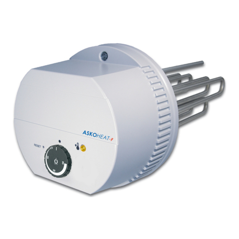
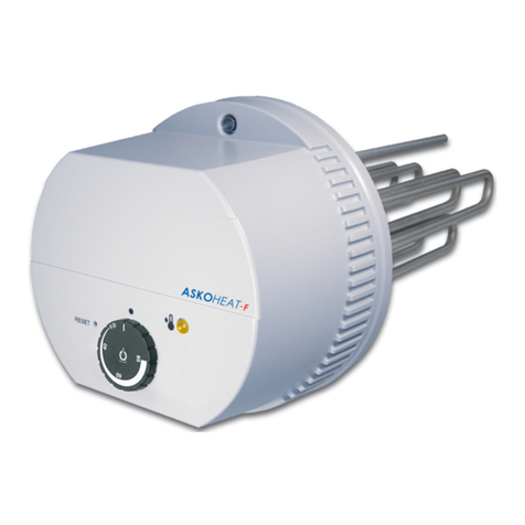
ASKOMA ASKOHEAT-F+ User manual

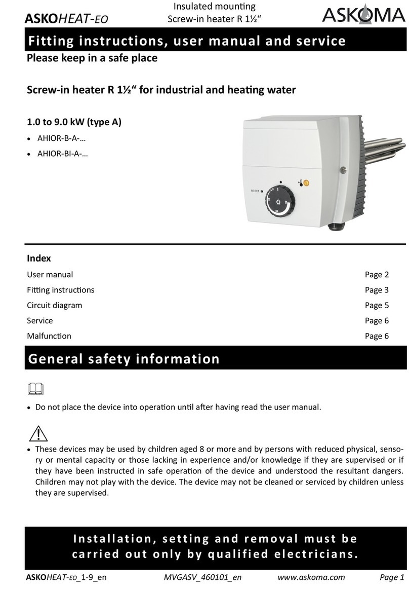
Fitting instructions, user manual and service
ASKOHEAT‐F+ MVGASV_012‐6791_V01_en www.askoma.comPage1
Flange heater Ø 180mm
for industrial and heang water
AHFR‐BI‐plus‐1.75 up to 5.8 kW
AHIR‐BI‐plus‐1.75
AHIR‐BI‐plus‐3.5
AHIR‐BI‐plus‐4.4
AHIR‐BI‐plus‐5.8
Index
GeneralsafetyandassemblyinformaonPage2
OperanginstruconsPage3
AssemblyinstruconsPage4
UsermanualPage6
OperangcondionsPage7
ElectricaldiagramPage8/9
ServicePage10
MalfunconPage10
Please keep in a safe place
ASKOHEAT‐F+ FlangeheaterØ180mm

Assembly information
The device must be installed horizontally, an installaon from above or below is not permiet for
safety reasons.
Makesurethattheheangtubesareenrelycoveredbytheliquidbeforeplacingintooperaon.
Thecirculaonoftheliquidshallnotbeinhibited.
Operangdata,applicaon,dimensionsandmodeloftheflangeheaterareontheidenficaonplate
andcircuitdiagramonthedevice,respecvelyinsidethehousingcover,orcanbefoundinthefing
instrucons/usermanuals.
Donotplacethedeviceintooperaonunlaerhavingreadtheusermanual.
Thesedevicesmaybeusedbychildrenaged8ormoreandbypersonswithreducedphysical,senso‐
ryormentalcapacityorthoselackinginexperienceand/orknowledgeiftheyaresupervisedorif
theyhavebeeninstructedinsafeoperaonofthedeviceandunderstoodtheresultantdangers.
Childrenmaynotplaywiththedevice.Thedevicemaynotbecleanedorservicedbychildrenunless
theyaresupervised.
General safety information
Installation, setting and removal must be
carried out only by qualified electricians.
ASKOHEAT‐F+ MVGASV_012‐6791_V01_en www.askoma.comPage2
FlangeheaterØ180mm
ASKOHEAT‐F+

Operating instructions
Important information
Ifaheatexchangerisfiedinthesametank,thecontrollermustlimitthetemperaturecausedbythe
heatexchangerto85°C.Thispreventsthesafetytemperaturelimiteroftheflangeheatertripping.
Safety temperature limiter
Thesafetytemperaturelimitermaytripattemperatureslowerthanapprox.–15°C(e.g.transportaon
orstorage).Ifthishappens,presstheresetbuon,seepage6“usermanual”.
The device may only be used to heat water.
Corrosion protection
Pleasenote:Thisheangelementisapplicableinstainlesssteelboileraswellasinblacksteel/black
steelenamelledboilers.SelectthesengsviaDIPswitchaccordingtotheboilertype.
Foraninstallaonoftheheangelementintoblacksteelorblacksteelenamelledboilers,theredslide
switch(DIPswitch)hastobeleinposion“Schwarzstahlspeicher”(factoryseng).
Wheninstallingtheheangelementintoastainlesssteelorchromesteelboiler,theslideswitch
(DIPswitch)hastobeswitchedtoposion“Edelstahlspeicher”.
Electrical connection
Thedeviceisintendedforfixedconnecononlyandmaybeconnectedonlytofixedcables.Selecta
cablecross‐seconsuitableforthepowerrangofthedevice.Allpolesofthedevicemustbeableto
bedisconnectedfromthemainsbymeansofanatleast3mmisolangdistance.ThePEwiremustbe
100mmlongerthantheotherconductors.
In the event of the following the guarantee is void:
‐ Notcomplyingwiththispaperwork„Finginstrucons,usermanual,andservice“
‐ Notcomplyingwiththestorageheatermanufacturer'sfinginstrucons
‐ Technicalmodificaons,repairsortamperingwiththedevice(includingexchangingthethermostat)
‐ Applicaonsforwhichthedevicewasnotdesigned
‐ Incorrectoperaonandmaintenance
‐ NotcomplyingwithdirecveVDI2035
‐ Manipulaonsontheoperangsoware
‐ Undocumentedparameterizaonsviathedocumentedinterfaces
ASKOHEAT‐F+ MVGASV_012‐6791_V01_en www.askoma.comPage3
ASKOHEAT‐F+ FlangeheaterØ180mm

Assembly instructions
ASKOHEAT‐F+ MVGASV_012‐6791_V01_en www.askoma.comPage4
ASKOHEAT‐F+
1.
6.
3. 4.
5.
2.
Screw the flange heater including the seal onto the storage tank,
note the installation position, see „TOP“ sticker
Tighten screws by hand
Carefully unscrew the housing cover
Clean the sealing surface of the flange
Tighten the screws with a torque wrench
Fill the tank and check for leaks
FlangeheaterØ180mm

Connect flange heater electrically
‐Plug Z1—Connectthepowersupplytotheheangelementasfollows:
Connecon1:L1
Connecon2:L2
Connecon3:L3
ConneconN:N
ConneconPE:PE
‐Plug Z2—Temperaturesensor(oponal)
Connecon1:Temperaturesensor1
Connecon2:Temperaturesensor2
Connecon3:Temperaturesensor3
Connecon4:Temperaturesensor4
Connecon5:GND
Connecon6:RelayK4
‐Plug Z3—Heatpumprequest/0‐10Vanaloguesignal(oponal)
Connecon1:GND
Connecon2:Heatpumprequest
Connecon3:Analogueinput0‐10V
Connecon4:RS485:A
Connecon5:RS485:B
Connecon6:RS485:GND
‐Plug Z4—LANconneconviadatacableandRJ45socket
Assembly instructions
ASKOHEAT‐F+ MVGASV_012‐6791_V01_en www.askoma.comPage5
ASKOHEAT‐F+ FlangeheaterØ180mm

User manual for the user and qualified installer
Device description
TheASKOHEAT‐F+ isswitchedin7stepsviathedigitalModbusinterfaceortheanalogue0‐10Vinput.In
addion,themaximumlevelupto24hourscanbeacvatedviathe„EmergencyOn“buon(Pos.3)or
thedigitalinput„Heatpumprequest“.
Theuseoftheinterfaceisdescribedinaseparatedocument(Modbusprotocl)andcanbedownloaded
fromourhomepage.
Temperature control
Themaximumtemperaturecanbeconnuouslyadjustedwiththerotaryknob(pos.1).Therangeex‐
tendsfrom„Out“toapprox.85°C.Foreconomicreasons,itshouldbesettoapprox.65°C.
Whenthetemperatureisreached,thedeviceswitchesoffandonagainautomacallyifnecessary.
Safety temperatur limiter
Ifthesafetytemperaturelimiterhastripped,youcanresetitwitha"00screwdriver"throughthe
openingmarked"Reset".Thiscannotbedoneunlthetemperaturehascooleddownbyapprox.10K.
Emergency operation „Emergency On“
Themaximumheangoutputcanbeswitchedonimmediatelywiththe„EmergencyOn“buon.Todo
this,pressthebuonforatleast2seconds.Thismaybenecessaryintheeventofafaultorifaddio‐
nalheatisrequired.Toswitchoff,pressthebuonagainforatleast2seconds.Forsafetyreasons,the
ASKOHEAT‐F+ automacallyswitchesbacktonormaloperaonaer24hours.
Safety:EN60335‐1/‐2‐21/‐2‐73
EMC:EN55014‐1/‐2
CEM:EN62233
IPCode:EN60529
Applicable
standards
Pos.1Temperaturecontrol
Pos.2Resetbuon
Pos.3EmergencyOn
Pos.4Operanglights
ASKOHEAT‐F+ MVGASV_012‐6791_V01_enwww.askoma.comPage6
ASKOHEAT‐F+ FlangeheaterØ180mm

Operating conditions
LED 1: STATUS
Green Connecontoacontroldevice(e.g.ASKOMAenergymanager)viaModbusTCP
Yellow Heangmode(whenconnectedtocontrolviaModbusTCP)
Red Heangmode(withoutconnecontocontroldevice)
Blue Legionellaproteconisacve
White Automacswitch‐off occursaer24hours(EmergencyOn,Heatpump
request,0‐10Vinput)
Red / Blue blinkingError(mustbereadoutviaacontroldeviceorASKOMAenergymanager)
LED 2: CONNECTION
Yellow blinking Connecontolocalnetwork(LAN)
LED 3: MODE
Green Analogue0‐10Vinputisacve
Red Heatpumprequestisacve
Red blinking Emergencymode„EmergencyOn“isacve
Yellow Emergencymodeandanalogue0‐10Vinputareacve
Blue StepswitchingviaModbusTCPisacve
ASKOHEAT‐F+ MVGASV_012‐6791_V01_enwww.askoma.comPage7
ASKOHEAT‐F+ FlangeheaterØ180mm

Electrical diagram
WARNING! Allpowersupplycircuitsmusthavebeenswitchedoffbeforeaccessing
theconneconterminals.
Electrical and connecon diagram 1.75 kW
AHFR‐BI‐plus‐1.75
ASKOHEAT‐F+ MVGASV_012‐6791_V01_enwww.askoma.comPage8
ASKOHEAT‐F+ FlangeheaterØ180mm

Electrical diagram
WARNING! Allpowersupplycircuitsmusthavebeenswitchedoffbeforeaccessing
theconneconterminals.
Electrical and connecon diagram 3.5 kW ‐5.8 kW
AHFR‐BI‐plus‐3.5
AHFR‐BI‐plus‐4.4
AHFR‐BI‐plus‐5.8
ASKOHEAT‐F+ MVGASV_012‐6791_V01_en www.askoma.comPage9
ASKOHEAT‐F+ FlangeheaterØ180mm

ASKOHEAT‐F+ MVGASV_012‐6791_V01_en www.askoma.comPage10
ASKOHEAT‐F+
Service
1.
2.
Malfunction
Reset
Seeusermanualforthe
qualifiedinstaller.
Thedevicemustbe
cleaned(descaled)with
asuitableprofessional
descalingagent,e.g.
citricacid.
Ifthesafetytemperature
limitertrips,thereisafault
orerror.Aqualifiedexpert
mustinspectthesystemin
thiscase.
The version currently valid can be downloaded under "Downloads" from our homepage
2x / year
Whentheheaterisusedinhardwaterareasitmustbe
regularlydescaled.
It is imperave that the local circumstances are paid aen‐
on to.
Thebuildupofscaleintheheangelementcanleadtothe
acvaonofthesafetytemperaturelimiterorthermal
overloadingtherebydestroyingtheheangelements.
In such cases the guarantee is not valid!
New
Needs cleaning
For technical data see the data sheet Subject to technical alteraons
FlangeheaterØ180mm
This manual suits for next models
4
Table of contents
Other ASKOMA Heater manuals
Popular Heater manuals by other brands

Ancona
Ancona Prima Dual User's manual & installation instructions

Weber
Weber R272TC operating manual

King Electrical
King Electrical K Series Installation, operation & maintenance instructions

HEALLUX
HEALLUX Taal manual

Gabarron
Gabarron Ingenium RX6ELST Installation instructions and user guide

REMKO
REMKO VRS Series Operation,technology,spare parts