10 309425
Pump Service: 3030
Repair kits are available. See the Parts Lists (page 16). For the best results, use all parts in the kits.
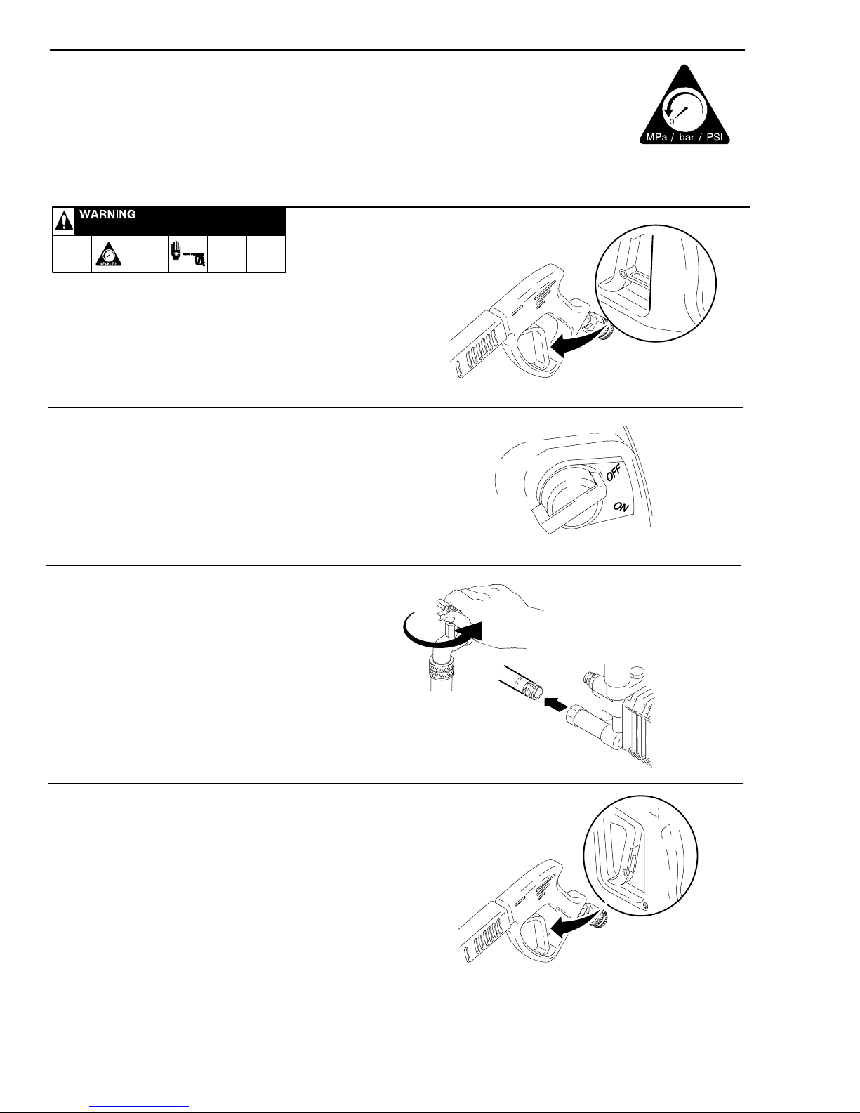
Relieve pressure, page 4.
NOTES:
DMetric wrenches needed: 6 mm, 13 mm, 27 mm.
DTool Kit 800271 contains tools for removing packing
retainers .
DDrain and refill pump after 50 hours of operation.
Valves
Order Valve Assembly Kit 804402.
1. Remove hex plug from manifold using a 27 mm
socket.
2. Examine o-ring seated under hex plug. Replace if
cut or distorted.
3. Remove valve assembly from cavity; the assembly
might come apart.
4. Install new valve, o-ring and hex plug. Torque to 73
ft-lb (99 NSm).
NOTE: Retorque plug after 5 hours of operation.
Pumping Section
1. Remove 8 capscrews and lockwashers from mani-
fold using a 6 mm wrench.
2. Carefully separate manifold from crankcase.
NOTE: If stuck, tap manifold lightly with a soft mallet
to loosen it.
CAUTION
To avoid damaging plunger or seals, keep manifold
properly aligned with ceramic plungers when you
remove it.
3. Carefully examine each plunger for any scoring or
cracking, and replace as necessary.
Servicing Plungers
Order Plunger Repair Kit 243430. It includes replace-
ment retainers, o-rings, washers, and backup rings for
three cylinders.
1. Turn plunger retaining nut 5 or 6 turns using a 13
mm wrench to loosen. Push plunger toward crank-
case to separate plunger and retaining screw.
2. Remove nut from plunger and examine o-ring,
backup ring, and copper bearing/gasket washer.
Replace these parts if necessary.
3. Remove plunger and flinger from plunger shaft.
Clean and replace parts as necessary.
4. Inspect plunger shaft for oil leakage from crank-
case. If leaking is obvious, replace oil seals. Other-
wise, DO NOT remove these seals, because they
cannot be reused. Order Oil Seal Kits 804033 for
replacing the seals.
5. Lightly grease the flinger (and oil seal if it is being
replaced), and replace on plunger shaft. Then
install plunger.
6. Lightly grease retaining screw and outer end of
plunger. Place washer, o-ring, and backup ring
around screw, and install nut through plunger.
Torque to 14.4 ft-lb (19.5 NSm).
NOTE: If replacing packings, see Servicing V-pack-
ings, page 11.
7. Lubricate outside of each plunger. Slide the mani-
fold onto the crankcase, being careful not to dam-
age seals.
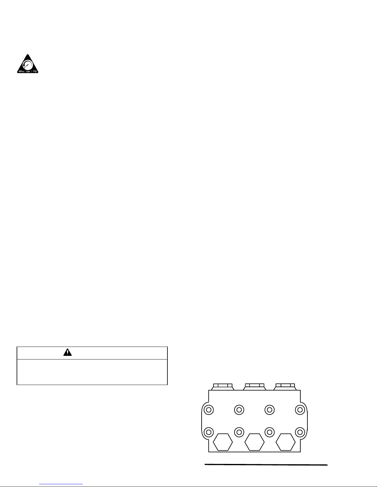
8. Install capscrews and washers finger tight. Torque
screws to 22 ft-lb (30 NSm) following tightening
pattern (Fig. 2). Uneven tightening could cause
manifold to bind or jam.
14
2
3
5
8
7
6
9278
Fig. 2